
Related Manuals for Ametek TRACE ANALYTICAL ta7000F Series


Summary of Contents for Ametek TRACE ANALYTICAL ta7000F Series
- Page 1 TRACE ANALYTICAL MODEL ta7000F Gas Purity Monitor User Manual Process Instruments Western Research 455 Corporate Boulevard Newark, DE 19702 PN T900-014 Rev. A...
- Page 2 If the instrument or procedures are used for purposes over and above the ca- pabilities specified herein, confirmation of their validity and suitability should be obtained; otherwise, AMETEK does not guarantee results and assumes no obligation or liability.
-
Page 3: Table Of Contents
Contents About This Document ..................5 Safety Notes ......................5 Grounding ......................6 Important Safety Information ................6 Warning Labels ...................... 7 Electromatic Compatibility (EMC) ..............8 General Safety Considerations ................9 Electric Hazard ..................9 UV Light ....................9 Mercury Vapor .................. - Page 4 Start Up and Operation 31 Power Up ....................31 Using the Menu Keys ..................32 Operator state diagram ..................33 Warm Up....................... 33 Main Menu Screens .................... 35 Page Screens ......................36 Setting the Clock ....................37 Temperatures......................38 Calibration ......................39 Auto Calibration ....................
-
Page 5: About This Document
About This Document This manual is intended as a guide for operation of the ta7000F. This manual is notintended as a service guide and does not contain service information. The ta7000F should only be operated by personnel who have been properly trained in the procedures required for safe operation of the ta7000F. -
Page 6: Grounding
Grounding Instrument grounding is mandatory. Performance specifications and safety protection are void if instrument is operated from an improp- erly grounded power source. WARNING Verify ground continuity of all equipment before applying power. Important Safety Information Before working on the ta7000F, read and understand the following Notes, Warnings, and Cautions, regarding safety and other required information. -
Page 7: Warning Labels
Achtung - Heiße Oberfläche Environmental Information (WEEE) This AMETEK product contains materials that can be reclaimed and recycled. In some cases the product may contain materials known to be hazardous to the environment or human health. In order to prevent the release of harmful substances into the environment and to conserve our natural resources, AMETEK recommends that you arrange to recycle this product when it reaches its “end of life.”... -
Page 8: Electromatic Compatibility (Emc)
Electromagnetic Compatibility (EMC) Read and follow the recommendations in this section to avoid perfor- mance variations or damage to the internal circuits of this equipment when installed in harsh electrical environments. CAUTION The various confi gurations of the Heater should not produce, or fall victim to, electromag- netic disturbances as specifi... -
Page 9: General Safety Considerations
General Safety Considerations Components and Functions The following safety items must be observed to avoid personal injury and to prevent damage to the ta7000F analyzer. All personnel involved in installation, operation or service of the analyzer should be thoroughly familiar with these items. These considerations are in addition to all site specific safety procedures. -
Page 10: Warranty And Claims
(90) days from date of shipment. Resale items warranty is limited to the transferable portion of the original equipment manufacturer’s warranty to AMETEK. If you are returning equipment from outside the United State, a statement should appear on the documentation ac- companying the equipment being returned declaring that the goods being returned for repair are American goods, the name of the firm who purchased the goods, and the shipment date. -
Page 11: Overview
OVERVIEW Model ta Gas Purity Monitor Introduction The ta7000F Process Gas Analyzer is a trace level gas chromatograph ca- pable of detecting sub-ppb concentrations of contaminants in sample gas matrices. The system consists of a microprocessor controlled gas chro- matograph utilizing the Trace Analytical Flame Ionization Detector (FID). Because of the specific nature of the detection method, analysis times are rapid and chromatographic complexity is minimized. -
Page 12: Reduction Gas Detection
Flame Ionization Detection Species eluting from the FID column set pass immediately into the heated bed of ruthenium oxide (Ru )) and the flame detector. Within the ru- thenium oxide bed, the general reaction occurs: + (2+X)H => CH O (vapor) Where CO is an appropriate carbon-oxygen compound gas. - Page 13 Data is presented via the front display panel. Alternatively data may be obtained through an RS232 serial computer interface and HP/GL parallel printer interface located on the rear panel. With optional interface kits, two components may be assigned to separate trend channels to provide a continuous signal proportional to the con- centration of the assigned component.
- Page 14 This page left blank. 14 | Model ta7000F Gas Purity Monitor...
-
Page 15: Specifications
Specifications Model designation and detection limit specifications Sample Gas Model Lower Detection Limit NMHCppb Nitrogen ta7000F-N2 < 0.5 < 1.0 < 2.0 Argon ta7000F-Ar < 0.5 < 1.0 < 2.0 Helium ta7000F-He < 0.5 < 1.0 < 2.0 Oxygen ta7000F-O2 <... -
Page 16: Sample Gas Supplies
Vent pressure Atmospheric pressure vent is opti mal, ± 0.5 psig maximum FlowRate 300 cc/min minimum, sample bypass at 50 cc/min * 1/4-inch face seal x 1/16-inch adapter fi ttings are available from Ametek 16 | Model ta7000F Gas Purity Monitor... -
Page 17: Gases
Actuator Gas Inlet Fitting 1/8-inch VICI compression fitting Inlet Pressure Range 70 to 150 psig (4.8 to 10.2 bar) Gas Type Inerts (Nitrogen, Argon, Helium), 7 nines or better or CDA, dewpoint < -65 °C Gas Type (for ta7000F-O Inerts (Nitrogen, Argon, Helium), 7 Only) nines or better Calibration Gas... -
Page 18: Outputs
Nitrogen Carrier Gas (for Oxygen and Hydrogen models only) Inlet Fitting 1/4-inch Male face seal fitting* Inlet pressure range 70 to 90 psig (4.8 to 6.1 bar) Inlet pressure stability + 2%, UHP regulator required Flow rate 300 cc/min Purity 99.9999% (<... -
Page 19: Com Ports
Field 1 Field 2 Field 3 Field 4 Field 5 Field 6 Field 7 Field 8 EDL / Single Date & Time Analyzer Run / ta7000 Impurity Concentration Analysis of RUN Serial # Maintenance Error Status Name in ppb x 100 The following defi... - Page 20 The Parallel Printer Port uses a standard 25-pin female D-type connec- tor. The printer port follows standard parallel printer protocols. The analyzers are compatable with Hewlett Packard printer’s model numbers HP-6xx, HP-7xx, and HP-8xx. AMETEK recommends using one of these suggested models. Parallel Printer Port LPT1...
-
Page 21: Analyzer Description
ANALYZER DESCRIPTION Front Panel and User Interface The front panel is where the user interface is found. The user interface is a combinationof the display screen and menu keys. The display screen shows information and options for running the ta7000F. The Menu Keys correlate to menu labels on the display screen and are used for all input to the operating system. -
Page 22: Display Screen
Gas Connections (O2 and H2 models only) A/C Power Connector Communication Ports Printer Port FID Shut-Off Purifier Rear Panel Display Screen The display screen is where the instrument displays all current informa- tion and options.The display is separated into three sections. The top section of the screen is the Status Bar. - Page 23 Display screen User Manual | 23...
-
Page 24: Installation
• Power Cord • Operating Manual If any evidence of damage exists, immediately contact the shipping com- pany, save the original shipping container, and notify Ametek customer service as soon as possible for consultation. Location and Environment The area where the Reduction Gas Analyzer is to be operated should be clean with minimum particulate matter and dust in the air. -
Page 25: Electrical Preparations And Connections
gas containers inside the building where temperature fluctuations are at a minimum. Have adequate ventilation around the instrument area without any high flow velocity draft directly onto the analyzer. Be sure not to block any vent slots in the rear or top of the analyzer since limited air circulation will cause overheating and poor performance. -
Page 26: Regulators And Plumbing
4. Frequent power failures in the area where the analyzer is used are best taken care of by installing an uninterruptible power supply (UPS). The UPS will supply power instantly from batteries when the main power is interrupted. Proper power will be supplied for minutes or hours depend- ing upon the size of the battery. -
Page 27: Damage Prevention
Guidelines for prevention of damage PLEASE STUDY THIS MANUAL THOROUGHLY BEFORE IN- STALLING OR OPERATING THE INSTRUMENT. CAUTION Carrier Gas The RGD detectors can be destroyed if operated at temperature without flow. The carrier gas should remain flowing until all heated zones are below 50o C (2 to 3 hours). -
Page 28: Installation Instructions
CAUTION If any inconsistencies are encountered during installation, stop im- mediately. Do not continue the installation without direction from Ametek customer service. CAUTION Tools Suggested for Installation All connections are made using U.S. standard size conectors. -
Page 29: View Of Gas And Power Connections
The instrument connection is made at the “Actuator Gas” 1/8” VICI port on rear panel. Pressurize external line to 80 psig (Minimum 70 psig, Maxi- mum 150 psig). Connecting AC Power and Communications Cables IMPORTANT: Verify that the operating voltage of the instrument matches the available AC power. -
Page 30: Connect Ac Power And Communication Cables
If any of these does not oc- cur, turn the power off immediately and contact Ametek customer service or your local authorized service agent. -
Page 31: Using The Menu Keys
Using the Menu Keys The analyzer displays a set of labels across the bottom of the display screen. The set is called a menu because it presents the user with choices. Each choice on the menu will either lead to another menu or will perform a function. - Page 32 Menu Labels 32 | Model ta7000F Gas Purity Monitor...
-
Page 33: Operator State Diagram
Menus Operator State Diagram Power-up Warmup Warmup Edit Edit System Temperatures Page Warm-up Page Page and Status Settings Cool Page Return to Source Calibration Idle Settings Page Edit Blank Calib State Diagram screenm. This chart illustrates how the menus are arranged. Each large circle represents a screen that is displayed on the instrument. - Page 34 After pressing Warmup the instrument will begin heating critical zones and will perform a series of system tests. The results from these tests will appear on the Warmup screen. The Warmup menu item will also change to Cool. If you wish to stop the warm-up process, press the Cool key and the instrument will return to a completely neutral state.
-
Page 35: Main Menu Screens
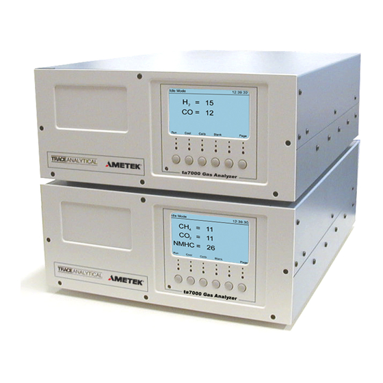
Main Menu After warm-up has completed successfully the main menu will be dis- played. The main menu is a set of primary choices leading to other menu options. The following table shows the choices available from the main menu. 12:39:30 Idle Mode NHMC = Page... -
Page 36: Page Screens
Page Screens Each time Page is pressed another user setup screen will be displayed. The following table shows a summary of information available from each page. If a page allows input, the cursor will be displayed and arrow keys will be available as menu items. Pressing Print generates an image of this screen to the external printer port. -
Page 37: Setting The Clock
System Settings Page The first Page Screen is for general configuration settings. The following list shows the function of each option for this screen Idle Mode 12:34:25 System Settings Ver. 2.70 Clock: 10-Jan-03 12:34:25 Print Chromatograms: EDL mode: -------------------- System Errors -------------------- Edit Print Page... -
Page 38: Temperatures
arrow keys to move the cursor in front of the EDL mode field. Press the Toggle key to toggle the mode on or off. EDL Mode averages the last 8 samples point by point to get an average sample and chromatogram. Us- ing this mode will help eliminate noise that occurs from run to run. -
Page 39: Calibration
Calibration Page Pressing the Page key three times will display the calibration informa- tion page. The calibration screen shows information about the most recent cali- bration run. Name is the gas species to be measured. Conc is the cylinder concentration (or blend) of the calibration gas connected to the instrument. -
Page 40: Manual Calibration
Idle Mode 12:34:25 Calibration Name Conc. Area Rfactor - - - - - - - - - - - - - - - - - - - - - - - - - - - - - - - - - - - - - - - - - 4800 42842 5300... - Page 41 external calibration gas source must be connected to the appropriate port on the rear panel of the analyzer marked AUX. Calibration gas specifica- tions are located in the specifications section of this manual. In calibration mode the instrument first checks for calibration gas pres- sure.
-
Page 42: Non Volatile Ram
Saving changes into Non-Volatile RAM After changes have been made by manual calibration or on any of the page screens, the system LED will turn red. This indicates that there is a system error or system state change. The analyzer must be in Idle or Warmup Mode in order to accept or save changes into Non-Volatile RAM. -
Page 43: Blank
# Indicates Cycle run will end Run Mode# 235 12:55:30 Cycle Run = 2.7 = 6.1 NHMC = 0.8 Idle Page Run Mode Screens Blank Pressing the “Blank Key” will begin a “blank” run. This is a system diagnostic run which tests the internal gas inside the instrument. No ex- ternal sample will be introduced into the systems during this run. -
Page 44: Shut Down
Shut Down System shut down for maintenance or for any other reason is very simple. If shut down is due to an emergency or for any safety reason, simply switch the instrument off using the A/C DIN Switch located on the rear panel of the analyzer (0 depressed is off). -
Page 45: Description Of Internal Components
DESCRIPTION OF INTERNAL COMPONENTS Front Panel Main Processor Module Display Flow Control Module Chassis Electrometer Control Module Detector Controller Chrom Module Detector Power Supply Power Supply Module Blender Carrier / Sample Stream Selector Regulator Rear Panel Front and Rear Panels User Manual | 45... -
Page 46: Error Messages
ERROR MESSAGES Error Messages Error Messages are viewed and acknowledged on the System Settings screen. When the Status LED on the front panel is red this indicates that there are system errors or the status of the analyzer has changed. The System Status page displays error messages that the system has encoun- tered. - Page 47 Analog Signal Zeroing Error The instrument has failed to zero the detectors analog signal. Vsig Minimum Voltage Limit This fault will occur if the RGD detector does not have the minimum Vsig (1000mv) for proper analysis. Typical Values are 1750-2250. Vsig cannot be above 2500.
-
Page 48: Dimensional Drawings
Dimensional Drawings ta7oooF 3-D View 48 | Model ta7000F Gas Purity Monitor... - Page 49 ta7ooof Side View User Manual | 49...
- Page 50 ta7oooF Top View 50 | Model ta7000F Gas Purity Monitor...
Need help?
Do you have a question about the TRACE ANALYTICAL ta7000F Series and is the answer not in the manual?
Questions and answers