
Related Manuals for Ametek TR-2000


Summary of Contents for Ametek TR-2000
- Page 1 TR-2100 Multi - Function Recorder Operation Manual Document No. 1086-816 Revision A AMETEK Power Instruments Tel: (800) 881-4156 255 N. Union Street Fax: (585) 238-4945 Rochester, New York 14605 Web: www.rochester.com...
-
Page 3: Table Of Contents
Table of Contents OVERVIEW ......................1 Triggered Records ..................... 2 Display Station....................3 1 INTRODUCTION ....................5 Input Connections ....................5 Recording Functions ..................5 Hard Disk Storage....................8 Network Capability ..................... 9 Printing....................... 9 Event Log......................9 2 HARDWARE DESCRIPTION ................11 Top Tray ...................... - Page 4 Status Output Connections ................22 Auxiliary Connections ..................23 Applying Power to the TR-2100 ............... 27 4 HARDWARE CONFIGURATION ..............29 Cross Triggering ....................30 5 CALIBRATION ....................33 Introduction ...................... 33 TR-2100 Calibration – Main Window ............... 34 CT Phase Correction ..................40 6 MAINTENANCE ....................
- Page 5 DNP Data Objects ................... 80 DNP v3.00 Device Profile Document ............... 81 The TR-2100 Implementation ................83 Point List ......................83 DNP Configuration ................... 86 APPENDIX IV – TROUBLESHOOTING............. 89 APPENDIX V – SYSTEM DRAWINGS............... 93...
-
Page 7: Overview
TR-2100 User Manual Overview The TR-2100 is a multi-function recorder that includes the features of many separate instruments for monitoring a power system. These include protection operations, system stability, and power quality. The voltages and currents on three phase lines are recorded via standard instrumentation transformers to 16-bit accuracy. -
Page 8: Triggered Records
TR-2100 User Manual Triggered Records When an abnormal event is detected, the analogue inputs and the digital switch data are stored in the TR-2100's memory. The stored data includes a period of time starting before the event occurs, until after conditions have returned to normal. This data frame constitutes a data record that may be printed in a graphical form with some initial measurements of the transient event. -
Page 9: Display Station
TR-2100 User Manual Display Station Display Station is a software application that runs on a standard Windows 95/98/NT based PC. This provides a communication link to all TR-2100, TR-100, and DL8000 monitors via an RS232 port, LAN, dial up modem, or WAN. All the recorder parameters can be updated remotely, and the analogue signals and digital status can be viewed on line. - Page 10 TR-2100 User Manual...
-
Page 11: Introduction
TR-2100 User Manual 1 Introduction The TR-2100 substation monitor is designed using leading edge computer hardware and software techniques. The high speed, high resolution recording, flexible triggering modes, and long term recording modes make it ideal for capturing all forms of line transients, protection operations, power quality surveys, real time display of station values, stability monitoring, switchgear maintenance, sequence of events recording, metering, etc. - Page 12 TR-2100 User Manual • Protection monitor The transient recorder is mostly used for monitoring protection operations. The VT & CT waveforms and auxiliary protection contacts are recorded before, during, and after the fault clearance. Expert System software can be used to analyze this data and report on any abnormalities.
- Page 13 As an alternative, individual disturbance records can be recovered and compared in Display Station Analysis. This allows voltages, power flow etc. to be compared at several points in a network. The TR-2000 can also communicate with other equipment that supports the IEEE 1344 – 1995 standard.
-
Page 14: Hard Disk Storage
TR-2100 User Manual • On-line Switchgear & Battery Monitor Because the TR-2100 is attached to strategic protection equipment, it can be used for condition monitoring. Circuit breaker operations are recorded and analysed by the Expert System. The measurements from each operation are stored in a database and these are used in a number of programmable contact wear formulae. -
Page 15: Network Capability
TR-2100 User Manual Network Capability The TR-2100 can be configured as part of an integrated monitoring network with multiple recorders at sub-stations within a region. Display Station can be located at the regional control center or headquarters. Communications between Display Station and the TR-2100s may be by dial-up modem on an internal or external phone system, or by a TCP/IP network connection on a company wide area network (WAN). - Page 16 TR-2100 User Manual...
-
Page 17: Hardware Description
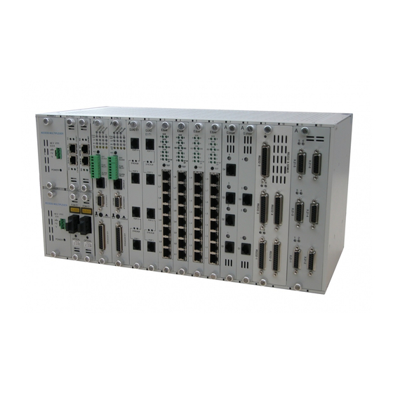
TR-2100 User Manual 2 Hardware Description The size of the rack mounting enclosure depends on the number of input boards fitted. Figure 1 Front view of TR2100 with 4 analogue input boards and 2 digital-only input Boards. Figure 2 Side view of TR2100 with 4 analogue input boards and 2 digital-only input Boards. -
Page 18: Top Tray
TR-2100 User Manual Figure 3 Internal view of TR2000 The top tray houses the processor and acquisition board and the power supply, while the bottom tray(s) holds the input conditioning board(s). Top Tray On the top (or processor) tray, the middle board is the Pentium processor board and the top board is the acquisition board. -
Page 19: Bottom Tray
TR-2100 User Manual Bottom Tray The bottom tray(s) hold the input boards, which contain the signal conditioning components for the analogue and digital input channels and the status relay outputs. It is connected to the acquisition board by two ribbon cables. The large central one is for the analogue and digital data signals, the smaller left hand one is for the status outputs and for programming the FPGAs on the input boards. - Page 20 TR-2100 User Manual On Line At turn on, this green LED will remain off until the TR-2100 has completed its internal self- tests. If everything is satisfactory, the light will turn on and will stay on as long as the TR- 2100 is acquiring data.
-
Page 21: Test Button
TR-2100 User Manual • The TR can’t read a sensor • There is a major difference between two sensors Test Button The 'Test' button on the front panel may be used at any time to check that the TR-2100 is operating correctly. -
Page 22: Printer
TR-2100 User Manual Duplicates the function of the front panel LED. Printer If a printer is connected to the TR-2100, it will report three separate events: • All entries to the event log • The system status will be printed with a test record when the Test button is pressed. -
Page 23: Fax
TR-2100 User Manual It is possible to set the TR-2100 to automatically send a fax of the fault record when the system is triggered. This allows users that do not have direct access to Display Station (i.e. maintenance) to be made aware of the fault. This feature is functional if the data modem used for normal communication with Display Station is compatible with Group 3 fax transmission. - Page 24 TR-2100 User Manual...
-
Page 25: Installation
TR-2100 User Manual 3 Installation The TR-2100 is available in a rack mount, a wall mount or a portable enclosure. All main supply, input and output connections are via screw terminals at the rear of the case. Communications, printer and other auxiliary connectors are also on the rear panel. The only exception is the program plug, which is for temporary use and is on the front panel. -
Page 26: Power Supply Connection
TR-2100 User Manual Power Supply Connection The main power supply is connected to the terminal block at the lower left of the rear panel. If a DC supply is being used, the polarity must be observed. The actual voltage specified will be indicated in the System Drawings located in Appendix V of this manual. - Page 27 50 V – 150 V for recording tripping battery voltage 2V for Hall effect CT for monitoring battery current * High voltage ranges require use of an external Voltage Divider Box, available from AMETEK. For non-sinusoidal signals, a DC input can be specified in the Display Station configuration.
-
Page 28: Status Output Connections
TR-2100 User Manual Digital Inputs There can be between 16 and 160 digital inputs. These are normally used for monitoring the operation of protection relays and switchgear via auxiliary contacts. The digital inputs must have a DC power supply connected externally and the voltage must be as specified in the System Drawings in Appendix V. -
Page 29: Auxiliary Connections
TR-2100 User Manual Auxiliary Connections Serial and Parallel Ports If an external modem or local printer has been specified, they are connected to the 9-pin D and 25-pin D connectors at the right of the rear panel. The RS232 connectors may also be used for direct connection of a computer for Display Station communications (Display Station communications require hardware handshaking signals RTS &... - Page 30 TR-2100 User Manual To distribute the one second pulse, the optical cables are ‘daisy chained’ together. The 1 PPS optical Output from the master recorder (with the GPS receiver) is connected to the next recorder’s Input. Its Output is connected to the next Input and so on. Any number of recorders can be linked in this manner.
- Page 31 REMOTE #2 REMOTE #3 1 PPS 1 PPS 1 PPS 1 PPS F.O. F.O. F.O. AERIAL Cable Cable Cable Coax Cable TIME CODE TIME CODE TIME CODE TIME CODE (OUT) (IN) (IN) (IN) Figure 6 Time-Synchronization Connections for Multiple TR-2000 Chassis...
- Page 32 TR-2100 User Manual Hardware Configuration If the TR2100 is to be set up as a Master unit, then set SW1 switch 6 to ON (GPS receiver present) and SW1 switch 7 to OFF (Master). SW2 switch 1 should be set to OFF (serial clock on COM2 disabled).
-
Page 33: Applying Power To The Tr-2100
TR-2100 User Manual Applying Power to the TR-2100 When all the relevant connections have been made, the system is switched on by first opening the front panel to expose the power switch. This is the toggle switch at the lower right of the enclosure. - Page 34 TR-2100 User Manual...
-
Page 35: Hardware Configuration
TR-2100 User Manual 4 Hardware Configuration The TR-2100 is available in many configurations with various user defined options. The values set for this machine at time of delivery can be found on the User Specification sheet and the System Drawings in Appendix V of this manual. The TR-2100 hardware configuration is set through two sets of 8 DIP switches on the acquisition board. -
Page 36: Cross Triggering
TR-2100 User Manual Cross Triggering Any number of TR-2100 recorders may be coupled together to form a system with any number of inputs (in multiples of 8, 16, 24, or 32 analogue inputs). This system uses the 'Triggered' status relay outputs and digital input 15 of each recorder. They are connected as follows: Battery + Digital inputs... - Page 37 TR-2100 User Manual The originating recorder will have a normal cause of trigger, but the others will show 'Cross- trigger' to identify the source of the original trigger. When the fault records are downloaded to Display Station, they may be viewed and printed individually.
- Page 38 TR-2100 User Manual...
-
Page 39: Calibration
If the error is more than 0.5%, then the channel in that unit should be recalibrated using the “MFR Calibration” software application that is available from AMETEK. The program allows simple calibration of the machine. Please note that the unit must be OFF LINE before running the Calibration program. -
Page 40: Tr-2100 Calibration - Main Window
TR-2100 User Manual TR-2100 Calibration – Main Window There are four options on the main window: Connect - connect to a TR-2100 Disconnect - disconnect from a TR-2100 Configure - configure the baud rate and communication port Exit - exit the program Communication Port Configuration Ensure the communication port has been set up correctly before attempting to connect to a TR-2100. - Page 41 TR-2100 User Manual TR-2100 Connection To make a connection, click on the Connect button. The program will attempt a connection by looking for a CLI command prompt. If this is successful, it will attempt to read the EEPROM chip on the first board of the system. Once the values have been read from the board, the actual input values will start to be displayed.
- Page 42 TR-2100 User Manual Once any adjust button has been pressed, a command is sent to the TR-2100 that updates offset values in the memory of the TR-2100. Although the TR-2100 has its local values updated, the actual EEPROM has not been updated at this stage. The process of writing to the EEPROM is a slow process.
- Page 43 TR-2100 User Manual shunt error. In this case, the test current can be found by dividing the shunt resistor value (found in the CT section of the User specification Sheet) into the equivalent test voltage: Test voltage = 1.000V Shunt = 130 ohms Test current = 7.6923mA Therefore, a test current of 8.000mA would be acceptable The TR-2100 can be calibrated using a DC or AC signal.
- Page 44 TR-2100 User Manual Once these values have been set up, the Calibration program displays will be giving relevant information. The actual amplitude field will display the value that the input card would report if no gain adjustment were applied. The card gain field gives a number between 0 and 2.0 that represents the gain applied to the actual amplitude.
- Page 45 TR-2100 User Manual Answer “Yes” to this question if all the adjustments for the card have been made and the card has been successfully calibrated. The actual process of writing to the card will take approximately 90 sec for each input board. Once the values on the display start moving again, the card has been updated.
-
Page 46: Ct Phase Correction
TR-2100 User Manual CT Phase Correction CT phase correction is not part of the calibrate program described above. Details are included here to complete the adjustment of the input scaling parameters of a TR-2100 to ensure maximum accuracy. The correction values are computed and set manually. Inputs derived from interposing CTs and some other forms of transducer will normally suffer from phase shift error. -
Page 47: Maintenance
TR-2100 and Display Station 32 Communication Software will be very helpful and is recommended. It is also recommended that two persons perform this procedure. If you have any questions or encounter problems, please contact the AMETEK Transient Recorder Technical Support Department at the numbers listed in this manual. - Page 48 TR-2100 User Manual RECOMMENDED TOOLS AND EQUIPMENT LIST: • Computer with one unused RS-232 port • AMETEK TR-2100 direct connect cable • DVM / Digital Volt Meter for DC • Basic technician hand tools, Phillips screwdriver, 5/16 Nut driver, etc.
- Page 49 TR-2100 User Manual 5. The ground braid that supports the Front Panel will need to be removed; one nut holds this inside on the left panel. Locate the two ribbon cables that go between the ACQ card and the Inputs Cards located above it. You will see a large and smaller ribbon cable that connects to all of the input cards.
- Page 50 TR-2100 User Manual Primary Power Input Figure 8 Primary Power Input Bracket Bracket Ribbon White Cables Connector Figure 9 Chassis Internals...
- Page 51 TR-2100 User Manual Figure 10 Sliding Out CPU Assembly Potentiometer Figure 11 PSU Potentiometer...
-
Page 52: Hardware Settings
TR-2100 User Manual Hardware Settings Acquisition Board Configuration Switches Set-up the acquisition board configuration switches as shown below. Reference the System Drawings for number of channels and options to be enabled. Bank 1 Table 7 Table 8 Switch Function Switch 3 Switch 4 Analogue Input Boards Digital-only cards... - Page 53 Input boards the digital inputs use resistors R1 – R32. Reference the Input Module schematics for resistor locations and change the value to match the Digital input voltage. Table 12 Input VDC Resistor Description Ametek Part No. (Nominal) 3.6K Carbon Composition 4716-130 Resistor (1W) 6.8K...
- Page 54 TR-2100 User Manual Figure 12 Analogue Input Board Jumpers...
- Page 55 TR-2100 User Manual Digital-only Input Board Jumper Locations Set the Digital-only Input Board configuration jumpers per Table 15. Refer to Error! Reference source not found. for the location of each configuration jumper. Table 15 Board No. Extra Digital Channels DIG BRD SEL 0 DIG BRD SEL 1 1-32* 33-64*...
-
Page 56: Hard Drive Format Procedure
TR-2100 User Manual Hard Drive Format Procedure WARNING! Only authorized personnel with computer service experience should perform this procedure. Contact the factory if there are any questions 2100 has an internal CLI program that will allow you to format the system’s internal hard drive. - Page 57 This includes Harmonic Logs, Trend Logs, and the standard TR events. Attach one end of the TR-2100 direct connect cable (AMETEK P/N 1077- 271) to the computer’s unused RS-232 port and the other end to the TR- 2100’s Local RS-232 port (found on the front panel).
- Page 58 TR-2100 User Manual Enter any name you desire. For example in this procedure, we will use “TR- 100_Comm2_19200”. Select the “OK” button when done and the screen depicted below will appear. Set “Connect using” to “Direct to Com*”, where * is the number of the RS- 232 port on the computer that is connected to the TR-2100.
- Page 59 TR-2100 User Manual This screen is where the computer’s RS-232 port properties are entered. Set “Bits per second” to 57600. Set “Data bits” to eight (8). Set “Parity” to none (N). Set “Stop bits to one (1). Set “Flow control” to Hardware. Select the “OK”...
- Page 60 TR-2100 User Manual PC conflict, or a failed port. Please call Technical Support for additional information or help. Now you will perform the following command to format the Hard drive. At the CLI> prompt, type in system formatdisk and press the Enter key. Formatting will take 30 minutes or longer to complete.
- Page 61 TR-2100 User Manual Create an event and retrieve it. If possible, have the computer call into the TR-2100 and retrieve an event.
-
Page 62: Installing Ne2000 Compliant Network Cards
TR-2100 unit, depending whether you need RJ-45 or Coaxial. If you don’t see what you need on the back panel, it is recommended that you call Ametek Technical Support. The network card must first be installed in a PC to be setup. It is recommended that the PC not already have a network card installed. -
Page 63: Acquisition Card Change-Out Procedure
TR-2100 User Manual Acquisition Card Change-Out Procedure REQUIRED EQUIPMENT LIST Computer with one unused RS-232 port TR-2100 direct connect cable Update package TR-2100 User Manual Basic technician hand tools ESD protection equipment CAUTION: TR-2100 UNITS CONTAIN STATIC SENSITIVE ELECTRONIC DEVICES. PROPER ELECTROSTATIC DISCHARGE (ESD) DAMAGE PREVENTION AND HANDLING TECHNIQUES MUST BE FOLLOWED. - Page 64 TR-2100 User Manual Cable (small round black cable) that you just removed. Remove the four screws that hold the GPS receiver and place the GPS receiver onto the new ACQ board in the correct location. Make sure that the GPS Receiver’s connector is pointing towards the edge of the new ACQ board.
-
Page 65: Converting An Analog Channel From V/I Or I/V
TR-2100 User Manual Converting an Analog Channel from V/I or I/V If a channel in the TR-2100 is to be changed from voltage to current, current to voltage, (or other) the following information should be noted. • Voltage channels have a maximum input of 212.12 Volts AC RMS, 300 Volts Peak, or 300 Volts DC. - Page 66 TR-2100 User Manual Figure 14 3. Open the front panel of the TR-2100 unit using the two top screws, and then turn the power switch (located in front of the Hard drive) OFF. 4. Next, remove the two white holding bars on either side of the unit. Continue by removing the gray ribbon cables attached to the Analogue input cards.
- Page 67 TR-2100 User Manual 7. Locate the correct jumper and move it ON or OFF as needed to set up the channel correctly. Figure 15 Analogue Input Board Jumpers Jumper References For Voltage input (212.12 V AC RMS) jumper is fitted in position JP0. For Current input (1.414 V AC RMS) jumper is not fitted.
- Page 68 TR-2100 User Manual Accuracy Verification 12. The accuracy of the changed channel should now be checked with a stable input source. This can be done quickly by setting the Full Scale Value (if voltage or current) to any level you wish to use. To calculate your Full Scale Values, use the following two formulas.
-
Page 69: Appendix I - Tr-2100 Specifications
TR-2100 User Manual Appendix I - TR-2100 Specifications Inputs No. of channels 8, 16, 24 or 32 Analogue 16 - 160 Digital Unlimited number of channels by cross-triggering systems Voltage inputs 57 – 120V RMS typical Other options available Current inputs 1A or 5A RMS typical Inputs via shunts or CTs CT phase lag correction... -
Page 70: Recording (Transient)
TR-2100 User Manual Recording (Transient) Recording resolution 16 bits (65536 levels) Dynamic range 96.3 dB Recording accuracy +/- 1 LSB Sample rate Up to 19,200 per sec. at 50 Hz Up to 23,040 per sec. at 60 Hz COMTRADE rates supported Analogues and digitals can have different rates Pre-fault time 2 - 500 cycles... -
Page 71: Fault Profile (Transient)
TR-2100 User Manual Fault Profile (Transient) Measured Values Fault duration, triggered channel Pre, during and post fault values per channel Maximum & minimum values per channel Selected digital channel timing Recording (Disturbance) Sample rate 2 x supply frequency (100/120 Hz) Pre-fault 10 sec. - Page 72 TR-2100 User Manual Harmonic log Maximum, minimum & average amplitude and phase angle per channel up to 64 harmonic Flicker log Pst value per phase for 1 line group every 10 minutes, to IEC 1000-4-15 Imbalance log Maximum, minimum & average imbalance (NPS/PPS*100%) for every line group, every 10 minutes Power log...
- Page 73 TR-2100 User Manual Triggering (Disturbance) Analogue channels Under & Over level Rate of change of real, reactive power Power Factor Frequency, rate of change of frequency (ROCOF) and frequency difference Power and frequency oscillation (0.1 - 15 Hz) Differential phase angle Imbalance &...
- Page 74 TR-2100 User Manual Communications Serial ports Up to (4) RS232 type Default setting 57600 baud, 8 bits, 1 stop, no parity Rates settable up to 115 kbaud Serial port 1 Uses: Local programming Data retrieval Real time data display Software updates Serial port 2 Uses: Remote programming...
- Page 75 TR-2100 User Manual Data Storage Buffer storage 30 Mbytes RAM (up to 128 Mbytes optional) Program storage 4 Mbytes flash ROM (up to 64 Mbytes optional) Permanent storage medium 3.5” Hard disk Capacity 12 Gbytes Interface standard Enhanced - IDE Printer (optional) Printer port Centronics type...
- Page 76 TR-2100 User Manual Status Relays Type Solid State Number of outputs Contact rating 1 Amp max 400 V dc / 280 Vac max Power & on line are N/C Attention & triggered are N/O Indication Power OK System on line Attention System Triggered Isolation...
- Page 77 13.7 Kg. (30.2 lbs) 16 channel 18.0 Kg. (39.7 lbs) 32 channel Environment -10 to 55 °C Operating temperature 14 to 131 °F Relative humidity 10 - 97% non condensing AMETEK reserve the right to change this specification without notice...
- Page 78 TR-2100 User Manual...
-
Page 79: Appendix Ii - Parameter Calculations
TR-2100 User Manual Appendix II – Parameter calculations Introduction The Multi Function Recorder (TR-2100) is a very high performance monitoring instrument that can implement the functions of over 12 different systems concurrently. These can be configured and interrogated locally or remotely over a dial up modem or corporate WAN. Inputs are connected to standard VT and CT secondaries as well as relay and switchgear auxiliary contacts. - Page 80 TR-2100 User Manual Time Measurement The TR-2100 uses the GPS navigation system as a source of absolute time. This generates UTC (universal co-ordinated time), which is the modern version of GMT (Greenwich Mean Time). This ensures that the time reference for each triggered event is accurate to better than 100 ns.
- Page 81 TR-2100 User Manual RMS Measurement The true RMS value for every channel is generated twice per cycle. The data for one cycle are squared and summed. The square root is taken of this value divided by the number of samples per cycle. The number of samples per cycle will vary with the sample rate. ∑...
- Page 82 TR-2100 User Manual Power (fundamental) Apparent Real Φ P V I Reactive Φ Q V I For delta VTs real power is computed using the two wattmeter method. Displacement power factor Φ Impedance (fundamental) Imbalance I V V (Ratio of NPS to PPS) −...
- Page 83 TR-2100 User Manual Harmonic Measurement A single cycle window is used to calculate the harmonic content of voltages and currents. A standard Discrete Fourier Transform (DFT) technique is used to calculate the amplitude and angle of each component. A minimum of 4 samples per cycle is required to extract a harmonic component accurately.
- Page 84 TR-2100 User Manual Reactive Power Reactive power is derived from the apparent and real powers. − Power Factor True power factor is the ratio of real to apparent power. True Total Harmonic Distortion (THD) The THD for an input is derived from the RMS and vector magnitude (V) −...
-
Page 85: Appendix Iii - Dnp Protocol
TR-2100 User Manual Appendix III – DNP Protocol Introduction Distributed Network Protocol (DNP Version 3.0) is an industry standard specification for SCADA communications between Master Stations, Host computers, Remote Terminal Units, and Intelligent Electronics Devices (such as the TR-2100 Transient Recorder). It is a public domain, non-proprietary protocol based on the IEC-870 standards, and is intended primarily for use in SCADA-like systems. -
Page 86: Dnp Data Objects
TR-2100 User Manual DNP Data Objects The DNP format divides data into several types of information called “Objects”. The specific information elements are uniquely identified by their object point number . This may be thought of as the index into an array of objects. As well as being identified as a particular object number, the data is identified as being a particular variation . -
Page 87: Dnp V3.00 Device Profile Document
• The Point List Tables • Configuration methods DNP V3.00 DEVICE PROFILE DOCUMENT Vendor Name: AMETEK Power Instruments Device Name: TR-2100 Digital Transient Recorder, using the Triangle MicroWorks, Inc. DNP 3.0 Slave Source Code Library, Ver 2.19 Highest DNP Level Supported:... - Page 88 TR-2100 User Manual DNP V3.00 DEVICE PROFILE DOCUMENT Timeouts while waiting for: Data Link Confirm: Configurable via DS32 Complete Appl. Fragment: None Application Confirm: Configurable via DS32 Complete Appl. Response: None Others: Transmission Delay: Configurable, via DS32 Inter-character Timeout: 1 sec. Need Time Delay: Configurable, via DS32 Frozen Counter Event scanning period:...
-
Page 89: The Tr-2100 Implementation
TR-2100 User Manual The TR-2100 Implementation The TR-2100 DNP implementation conforms to the standard for a Level 1 slave device. Implementation consists of the following static objects: • (3) Single-bit Binary Input without flag (Object 01 Variation 01) • (32) 16-bit Analogue Voltage values without flag points (Object 30 Variation 4) •... - Page 90 TR-2100 User Manual Analogue Inputs Analogue Inputs are implemented as Object 30 Var 4 (16-bit analogue input without flag) points. A total of 160 points are implemented, which represent: • Analogue Voltage values, 1 per analogue channel • Analogue Profile values, 4 per analogue channel (Pre-fault, Immediate, Final, Post- Clearance) The Analogue Voltage and the Analogue Profile points use different formulae to calculate actual engineering units.
- Page 91 TR-2100 User Manual Point Analog Input Point Analog Input Point Analog Input Index Name/Description Index Name/Description Index Name/Description Analog Channel 1 Channel 6 Final Channel 20 Pre-fault Analog Channel 2 Channel 6 Post-Clearance Channel 20 Immediate Analog Channel 3 Channel 7 Pre-fault Channel 20 Final Analog Channel 4 Channel 7 Immediate...
-
Page 92: Dnp Configuration
TR-2100 User Manual DNP Configuration To set the DNP communications format, open the Display Station32 Communications software, select ‘Configuration’ in the ‘Recorder’ menu, and then click on ‘DNP Parameters’. The following setup screen will appear. Note: Since the present implementation of DNP is on an RS232 link, some of the parameters are not used. - Page 93 TR-2100 User Manual Timeout This is the time the IED will wait for a Data Link confirmation. Valid numbers are 0 - 65535. Select/Operate arm timer This is the time period after the select command is received when the operate command will be performed.
- Page 94 TR-2100 User Manual...
-
Page 95: Appendix Iv - Troubleshooting
TR-2100 User Manual Appendix IV – Troubleshooting The first indication that a TR-2100 is not functioning correctly is normally that it will not make a remote connection. Before going on site, it is worth checking the phone line by ringing the TR-2100’s number and listening for the phone to be answered by the modem, followed by a series of tones. - Page 96 TR-2100 User Manual On-Site Checks Start with test 1). Follow the test numbers depending on the result of each test. After a change is made start with test 1) again. Is the green ‘Power’ light on? Yes 2) No 5) Press the ‘Test’...
- Page 97 TR-2100 User Manual There is no power to the TR-2100. Check the incoming supply and the fuse at the rear of the unit. There is also a fuse inside the power supply which is at the left rear of the bottom tray. Was everything correct? Yes12) No 16) Check that all the boards on the processor tray are seated correctly and all the ribbon cables are in place.
- Page 98 TR-2100 User Manual...
-
Page 99: Appendix V - System Drawings
TR-2100 User Manual Appendix V – System Drawings... - Page 100 TR-2100 User Manual...
- Page 105 For emergency service or repair status information, please contact the Repair Department at (716) 238-4993. WARRANTY — AMETEK warrants equipment of its own manufacture to be free from defects in material and workmanship, under normal conditions of use and service. AMETEK will replace any component found to be defective, upon its return, transportation charges prepaid, within one year of its original purchase.
Need help?
Do you have a question about the TR-2000 and is the answer not in the manual?
Questions and answers