Table of Contents
Advertisement
Quick Links
5-Phase Stepping Motor Unit
UFK·W
OPERATING MANUAL
Thank you for purchasing an Oriental Motor product.
This Operating Manual describes product handling procedures and safety precautions.
Please read it thoroughly to ensure safe operation.
•
Always keep the manual where it is readily available.
•
Table of contents
1 Introduction ......................................... 2
2 Safety precautions .............................. 4
3 Precautions for use............................. 6
4 Preparation ......................................... 8
4.1 Checking the product .............................. 8
4.2 How to identify the product model........... 9
4.4 Names and functions of parts................ 12
5 Installation......................................... 14
5.1 Location for installation.......................... 14
5.2 Installing the motor ................................ 14
5.3 Installing a load ..................................... 15
5.5 Installing the driver ................................ 17
6 Connection........................................ 18
6.1 Connection example.............................. 18
6.2 Connecting the power supply................ 19
6.3 Connecting the motor and driver........... 19
6.4 Grounding the motor and driver ............ 20
6.5 Connecting the input/output signals ...... 20
6.6 About input/output signals..................... 22
6.7 Timing chart........................................... 27
Series
7 Setting...............................................28
7.1 Step angle.............................................. 28
7.2 Adjusting motor currents ....................... 29
7.3 Pulse input modes ................................. 30
7.4 Automatic current off function................ 30
with an electromagnetic brake only)...... 31
8 Overheat protection function .............32
8.1 Stopping the motor operation ................ 32
to continue ............................................. 32
8.3 Canceling the O.H. output ..................... 32
9 Inspection .........................................33
actions ..............................................34
11 Specifications ....................................36
12 Options (Sold separately)..................37
HP-4071-4
Advertisement
Table of Contents

Related Manuals for Oriental motor UFK-W Series


Summary of Contents for Oriental motor UFK-W Series
-
Page 1: Table Of Contents
5-Phase Stepping Motor Unit UFK·W Series OPERATING MANUAL Thank you for purchasing an Oriental Motor product. This Operating Manual describes product handling procedures and safety precautions. Please read it thoroughly to ensure safe operation. • Always keep the manual where it is readily available. -
Page 2: Introduction
The product described in this manual has been designed and manufactured for use in general industrial machinery, and must not be used for any other purpose. Oriental Motor Co., Ltd. is not responsible for any damage caused through failure to observe this warning. - Page 3 1 Introduction Standards and CE Marking This product is recognized by UL and certified by CSA, and bears the CE Marking (Low Voltage Directive and EMC Directives) in compliance with the EN Standards. • Applicable Standards Applicable Standards Certification Body Standards File No.
-
Page 4: Safety Precautions
2 Safety precautions 2 Safety precautions The precautions described below are intended to prevent danger or injury to the user and other personnel through safe, correct use of the product. Use the product only after carefully reading and fully understanding these instructions. - Page 5 2 Safety precautions Maintenance and inspection • Do not touch the connection terminals of the driver immediately after the power is turned off (for a period of 30 seconds). The residual voltage may cause electric shock. Repair, disassembly and modification •...
-
Page 6: Precautions For Use
3 Precautions for use 3 Precautions for use This section covers limitations and requirements the user should consider when using the UFK·W series 5-phase stepping motor unit. • Conduct the insulation resistance measurement or withstand voltage test separately on the motor and the driver. Conducting the insulation resistance measurement or withstand voltage test with the motor and driver connected may result in injury or damage to equipment. - Page 7 3 Precautions for use • Preventing electrical noise Take the following anti-noise measures to prevent malfunction of the motor and driver due to external noise. Wiring the motor Use braided-screen cable for connection between the motor and driver. Wiring the input/output cables •...
-
Page 8: Preparation
4 Preparation 4 Preparation This section covers the points to be checked along with the names and functions of respective parts. 4.1 Checking the product Verify that the items listed below are included. Report any missing or damaged items to the branch or sales office from which you purchased the product. Verify the model number of the purchased unit against the number shown on the package label. -
Page 9: How To Identify The Product Model
4 Preparation 4.2 How to identify the product model Standard type, Standard type with electromagnetic brake UFK 5 6 6 A W M Blank: Standard type Standard type with electromagnetic brake UFK·W series Motor output shaft type A: Single shaft B Double shaft The length of the motor Frame size... -
Page 10: Combinations Of Motors And Drivers
4 Preparation 4.3 Combinations of motors and drivers • Standard type • Standard type with electromagnetic brake Unit model Motor model Driver model Unit model Motor model Driver model UFK564AW PK564AW UFK564AWM PK564AWM UFK564BW PK564BW UFK566AWM PK566AWM UFK566AW PK566AW UFK569AWM PK569AWM DFU1514W-M UFK566BW... - Page 11 4 Preparation PN geared type • • Harmonic geared type Unit model Motor model Driver model Unit model Motor model Driver model UFK566AW-N5 PK566AW-N5 UFK564AW-H50 PK564AW2-H50 UFK566BW-N5 PK566BW-N5 UFK564BW-H50 PK564BW2-H50 UFK566AW-N7.2 PK566AW-N7.2 UFK564AW-H100 PK564AW2-H100 UFK566BW-N7.2 PK566BW-N7.2 UFK564BW-H100 PK564BW2-H100 DFU1514W UFK566AW-N10 PK566AW-N10 UFK596AW-H50 PK596AW1-H50...
-
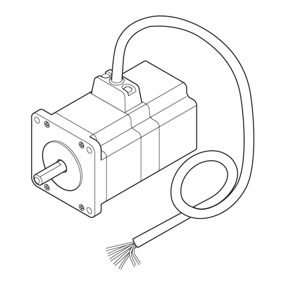
Page 12: Names And Functions Of Parts
4 Preparation 4.4 Names and functions of parts This section covers the names and functions of parts in the driver and motor. Motor Illustration shows the standard type with electromagnetic brake (UFK56 ). Mounting holes (four locations) Electromagnetic brake (Only for the standard type with electromagnetic brake) Output shaft Motor cable... - Page 13 4 Preparation Names Description POWER LED (green) Lit when the power is on. TIM LED (green) Lit when the excitation timing output is ON. O.H. LED (red) Lit when overheat protection is activated and the overheat output turns ON. Pulse input mode select switch Allows for the selection of 2-pulse input mode or 1-pulse input mode in accordance with the pulse output mode in the positioning controller.
-
Page 14: Installation
5 Installation 5 Installation This section covers the environment and method of installing the motor and driver, along with load installation. 5.1 Location for installation The motor and driver are designed and manufactured for installation in equipment. Install them in a well-ventilated location that provides easy access for inspection. The location must also satisfy the following conditions. -
Page 15: Installing A Load
5 Installation Tightening Frame size Effective depth Type of Motor type Bolt size torque [mm (in.)] of bolt [mm (in.)] installation [N·m (oz-in)] Standard type 60 (2.36) 2 (280) − Standard type with 85 (3.35) 3 (420) electromagnetic brake TH geared type 60 (2.36) 2 (280) 8 (0.315) -
Page 16: Permissible Overhung Load And Permissible Thrust Load
5 Installation 5.4 Permissible overhung load and permissible thrust load The overhung load and the thrust load on the motor’s output shaft or gear output shaft must be kept within the permissible values listed below. Failure due to fatigue may occur if the motor’s bearings and output shaft are subject to Note repeated loading by an overhung or thrust load that is in excess of the permissible limit. -
Page 17: Installing The Driver
5 Installation 5.5 Installing the driver Installation direction The driver is designed so that heat is dissipated via air convection and conduction through the enclosure. When installing the driver in an enclosure, it must be placed in perpendicular (vertical) position using the four mounting holes provided in the driver. -
Page 18: Connection
6 Connection 6 Connection This section covers the methods and examples of connecting and grounding the driver, motor, power and controller, as well as the input/output signals. 6.1 Connection example A connection example of an electromagnetic brake type is shown. Example of connection with a current sink output circuit Driver Controller... -
Page 19: Connecting The Power Supply
6 Connection 6.2 Connecting the power supply Connect the power cable to the driver’s power supply terminals. Connection method Connect the live side to the L terminal and the neutral side to the N terminal. Use a power supply capable of supplying single-phase 100-115 V±15% at 4.5 A or greater. -
Page 20: Grounding The Motor And Driver
6 Connection 6.4 Grounding the motor and driver Grounding the motor Install the motor to the grounded metal plate. Use a grounding wire thicker than AWG18 (0.75 mm When grounding, use a round terminal and affix it with a mounting screw over a crow washer. - Page 21 6 Connection Connector pin functions Pin No. Signal Description Type • Connector pin assignments +CW (+PLS) CW pulse (pulse) Input −CW (−PLS) +CCW (+DIR) CCW pulse Input (rotation direction) −CCW (−DIR) −C.OFF Output current off Input Electromagnetic brake ∗ −M.B.FREE Input release +C/S...
-
Page 22: About Input/Output Signals
6 Connection 6.6 About input/output signals Input signals All input signals of the driver are photocoupler inputs. The signal state represents the “ON: Carrying current” or “OFF: Not carrying current” state of the internal photocoupler rather than the voltage level of the signal. 5 VDC can be directly connected. - Page 23 6 Connection 1-pulse input mode Connect the controller pulse to Pin No.2 “−PLS input” and the rotating direction to Pin No.4 “−DIR input.” • When the DIR input is “ON,” a fall of the “PLS input” from “ON” to “OFF” will rotate the motor one step in the CW direction.
- Page 24 6 Connection • C.OFF (All windings off) input Use this signal when the motor’s output shaft must be mechanically rotated for position adjustment. Warning Do not turn the C.OFF input to “ON” while the motor is operating. The motor will stop and lose its holding ability.
- Page 25 6 Connection Output signals All output signals of the driver are photocoupler/open-collector outputs. The signal state represents the “ON: Carrying current” or “OFF: Not carrying current” state of the internal photocoupler rather than the voltage level of the signal. Use output signals with a power supply not exceeding 24 VDC and 10 mA. Note If these specifications are exceeded, the internal elements may be damaged.
- Page 26 6 Connection Example of TIM output not turning “ON” The figure below shows a condition in which the motor operates for a period of nine pulses at a step angle of 0.072°/step, and then operates for one pulse at a step angle of 0.72°/step. The TIM output will not switch to “ON”...
-
Page 27: Timing Chart
6 Connection Motor operation is continued Set the A.C.O. function select switch to “OFF: Automatic current off disable”. The O.H. output is turned “OFF” when the driver’s internal temperature reaches approx. 80 °C (176 °F). Output current remains on and the motor continues to operate. Then the electromagnetic brake is not actuated. -
Page 28: Setting
7 Setting 7 Setting This section covers the switching and settings of driver functions. Motor-current adjustment switches Pulse input mode select switch RUN:Adjusts the motor operating current. A.C.O. function select switch STOP:Adjusts the motor current in the stopped state. Electromagnetic brake function select switch Step angle setting switches ∗... -
Page 29: Adjusting Motor Currents
7 Setting 7.2 Adjusting motor currents Use the motor-current adjustment switches “RUN” and “STOP” to set current levels for the motor. Factory settings: [RUN] F: 1.4 A/phase [STOP] 9: 49% Motor-current adjstment switches The switch provides a selection of 16 (from “0” to “9” and “A” to “F”). The switch sets the amount of reduction in motor current relative to the operating current at 10 different levels between “0”... -
Page 30: Pulse Input Modes
7 Setting 7.3 Pulse input modes Either the 2-pulse or 1-pulse input mode may be selected in accordance with the controller used. Factory setting 2P (2-pulse input mode) Pulse input mode select switch Lever • When the motor is to be controlled through 2-pulse signal input via the CW pulse signal and CCW pulse signal, set the pulse input mode select switch to “2P.”... -
Page 31: Electromagnetic Brake Function (Motors With An Electromagnetic Brake Only)
7 Setting 7.5 Electromagnetic brake function (motors with an electromagnetic brake only) You can use the electromagnetic-brake function selector switch to set whether to actuate the electromagnetic brake when the motor is operating. Factory setting “M.B.F.” (release the electromagnetic brake) Electromagnetic brake function select switch Lever... -
Page 32: Overheat Protection Function
8 Overheat protection function 8 Overheat protection function Overheat protection is triggered when the driver’s internal temperature reaches approx. 80 °C (176 °F), upon which the O.H. output is turned “ON” and the O.H. LED (red) turns on. Warning If “A.C.O. (Automatic current off)” on the driver’s overheat-protection function is disabled, set it so that the motor is stopped upon detection of O.H. -
Page 33: Inspection
9 Inspection 9 Inspection It is recommended that periodic inspections be conducted for the items listed below after each operation of the motor. If an abnormal condition is noted, discontinue any use and contact your nearest office. During Inspection • Are any of the motor mounting screws loose? •... -
Page 34: Troubleshooting And Remedial Actions
10 Troubleshooting and remedial actions 10 Troubleshooting and remedial actions During motor operation, the motor or driver may fail to function properly due to incorrect speed setting or wiring. When the motor cannot be operated correctly, refer to the contents provided in this section and take appropriate action. - Page 35 10 Troubleshooting and remedial actions Phenomenon Possible cause Remedial action The motor missteps during Misalignment of the motor’s output shaft Check the coupling of the motor output shaft and acceleration or operation. and load shaft. load shaft. Excessive load or large fluctuation in the Check for a large fluctuation in the load during load.
-
Page 36: Specifications
11 Specifications 11 Specifications This section covers the main specifications of the UFK·W series 5-phase stepping motors. Refer to the catalog for detailed specifications, torque characteristics and dimensions. Motor Driver Degree of protection IP30 IP00 Operation Ambient −10 to +50 °C (+14 to +122 °F) 0 to +50 °C (+32 to +122 °F) environment temperature... -
Page 37: Options (Sold Separately)
12 Options (Sold separately) 12 Options (Sold separately) Extension cable These cables are used to extend the wiring length between the motor and driver.(Can not used for motors with an electromagnetic brake) Model Length [m (ft.)] Number of cores CC05PK5 5 (16.4) CC10PK5 10 (32.8) - Page 38 12 Options (Sold separately) −38−...
- Page 40 • Unauthorized reproduction or copying of all or part of this Operating Manual is prohibited. If a new copy is required to replace an original manual that has been damaged or lost, please contact your nearest Oriental Motor branch or sales office.
Need help?
Do you have a question about the UFK-W Series and is the answer not in the manual?
Questions and answers