Table of Contents
Advertisement
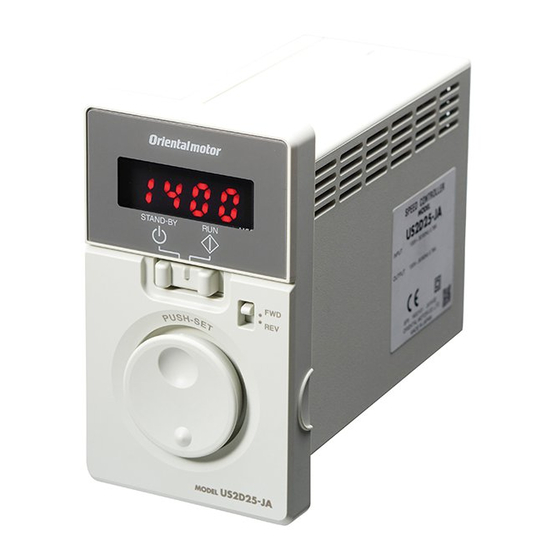
Speed Control Motor and Controller Package
US2
Series
OPERATING MANUAL
Thank you for purchasing an Oriental Motor product.
This Operating Manual describes product handling procedures and safety precautions.
• Please read it thoroughly to ensure safe operation.
• Always keep the manual where it is readily available.
D-loop represents the speed control motor which adopted Oriental
Motor's unique technology.
This product achieves high reliability using closed loop control in
addition to downsize the speed controller by digitizing the phase
control circuit.
HM-9350-3
Advertisement
Table of Contents

Related Manuals for Oriental motor US2D6-JA


Summary of Contents for Oriental motor US2D6-JA
- Page 1 HM-9350-3 Speed Control Motor and Controller Package Series OPERATING MANUAL Thank you for purchasing an Oriental Motor product. This Operating Manual describes product handling procedures and safety precautions. • Please read it thoroughly to ensure safe operation. • Always keep the manual where it is readily available. D-loop represents the speed control motor which adopted Oriental Motor's unique technology.
-
Page 2: Table Of Contents
Before use Only qualified and educated personnel should work with the product. Use the product correctly after thoroughly reading the section "Safety precautions." The items under contain important handling instructions that the user should observe to ensure Note safe use of the product. is described in the related handling items. - Page 3 Names of parts Speed controller Speed control motor Gearhead Protective Earth Operation switch Terminal p.15 Rotation direction switch Power supply cable Setting dial Motor cable Connecting p.14 Installing Operating p.16 When the front panel is removed Speed controller (rear side) Front panel Input signal terminal...
-
Page 4: Safety Precautions
Safety precautions 1 Safety precautions The precautions described below are intended to prevent danger or injury to the user and other personnel through safe, correct use of the product. Use the product only after carefully reading and fully understanding these instructions. Description of graphic symbols Indicates "prohibited"... -
Page 5: Preparation
Preparation 2 Preparation 2.1 Checking the product Verify that the items listed below are included. Report any missing or damaged items to the branch or sales office from which you purchased the product. Common to each type □ □ Motor ............ -
Page 6: List Of Combinations
„ Parallel shaft • combination type, round shaft type Motor Gearhead Speed controller Power supply voltage Model Motor model output power model model US2-26JA-o-„ SCM26GV-JA US2D6-JA Single-phase 100 VAC US2-26UA-o-„ SCM26GV-UA US2D6-UA Single-phase 110/115 VAC 2GVoB US2-26JC-o-„ SCM26GV-JC US2D6-JC Single-phase 200 VAC US2-26EC-o-„... -
Page 7: Names And Functions Of Parts
Preparation 2.4 Names and functions of parts Motor Parallel shaft • combination type Right angle • geared type Hollow shaft type Tachogenerator Tachogenerator Output shaft Motor Motor Mounting holes (four locations) Protective Earth Terminal Output Gearhead Gearhead shaft Mounting holes (four locations) Speed controller Front side... -
Page 8: Installation
Installation 3 Installation This chapter explains the installation location and installation methods. 3.1 Location for installation The motor and speed controller described in this manual have been designed and manufactured to be incorporated in general industrial equipment. Install them in a well-ventilated location that provides easy access for inspection. •... -
Page 9: X84; Installing The Round Shaft Type
Installation • Removing/Installing the gearhead The gearhead or the outlet position of the motor lead wires can be changed. Removing the gearhead from the motor Remove the gearhead by unscrewing the hexagonal socket-head screws holding the gearhead to the motor (2 locations). Illustration shows the view from motor case side. -
Page 10: X84; Installing The Right Angle • Geared Type
Installation „ Installing the right angle • geared type Machine tapped holes in the mounting plate, and secure the motor on the plate using hexagonal socket head screw set (supplied). The pilot section on the output shaft has been machined to in] for SCM4 type and Ø50 mm (h8) [Ø1.9685... - Page 11 Installation „ Right angle • hollow shaft type Mounting method of the load varies depending on the load shaft conditions. See the following figures. The hollow output shaft inside dimension is processed to a tolerance of H8, and incorporates a key slot for load shaft attachment. A load shaft tolerance of h7 is recommended.
-
Page 12: Permissible Radial Load And Permissible Axial Load
Installation 3.4 Permissible radial load and permissible axial load The radial load and the axial load on the output shaft of the motor (gearhead) must be kept under the permissible values listed below. Note Failure due to fatigue may occur when the motor (gearhead) bearings and output shaft are subject to repeated loading by a radial or axial load that is in excess of the permissible limit. -
Page 13: Installing The Speed Controller
Installation 3.5 Installing the speed controller The speed controller is designed so that heat is dissipated via air convection. There must be a clearance of at least 25 mm (0.98 in.) and 50 mm (1.97 in.) clearances in the horizontal and vertical directions, respectively, between the speed controller and enclosure or other equipment within the enclosure. -
Page 14: Connecting
Connecting 4 Connecting This chapter explains how to connect the speed controller and motor, input signal, and power supply, as well as the grounding method. Motor Speed controller Motor cable Power supply cable Grounding Power supply Cable fixing part The motor cable can be tightened using a supplied cable-tie. -
Page 15: Connecting The Motor And Speed Controller
Connecting 4.2 Connecting the motor and speed controller Connect the motor cable connector to the CN2 on the speed controller. Use a connection cable (supplied or accessory) when extending the wiring distance between the motor and speed controller. The connection cable can be connected up to 3 pieces. Flexible connection cables are also available as accessories. Maximum extension distance between the motor and speed controller: 10.5 m (34.4 ft.) [including 0.5 m (1.6 ft.) of the motor cable] •... -
Page 16: Operating
Operating 5 Operating 5.1 Operation procedure After connecting, operate the product as follows. Names of parts AC power ON Display The display is lit Operation switch (rotation speed) Setting dial Front panel Operation switch ⇒ STAND-BY The motor rotates. Rotation speed Rotation speed Factory setting: 90 r/min Decelerate... -
Page 17: To Adjust The Motor Rotation Speed
Operating 5.2 To adjust the motor rotation speed Setting the operation switch to the "RUN" side causes the motor to rotate. Setting the operation switch to the "STAND-BY" side causes the motor to stop. The speed while the motor is rotating can be adjusted with the setting dial. Operation switch Turning the setting dial slowly Setting dial... -
Page 18: Convenient Functions
Convenient functions 6 Convenient functions 6.1 Functions list Various settings can be performed when removing the front panel. Parameter type Display Setting range Factory setting • To display the rotation Speed reduction ratio 1.00 to 9999 1.00 speed of the gearhead •... -
Page 19: Panel Displays And Setting Items
Convenient functions 6.2 Panel displays and setting items Power ON : Turn the setting dial : Press the setting dial : Press the ESC key : Press the FUNCTION key Rotation speed monitor Rotation speed monitor Data setting The motor rotation speed is displayed. The display of the lowest digit is xed to "... -
Page 20: Data Locking For The Set Data
Convenient functions 6.3 Data locking for the set data The data setting can be locked so that the set rotation speed and parameters do not change. The setting of data and parameters cannot be changed using the setting dial while the data is locked. However, the setting data of each parameter can be checked even when the data is locked. -
Page 21: Soft Start/Soft Stop Function
Convenient functions 6.5 Soft start/soft stop function An impact on a load is suppressed by soft start/stop operation of the motor, and the motor starts running smoothly. The acceleration time and deceleration time is fixed to about 1 second at the time of shipment. When adjusting the acceleration time and deceleration time, change the setting of the "acceleration/deceleration time"... -
Page 22: Operating With External Signals
Convenient functions 6.7 Operating with external signals When the motor operation/standstill and rotation direction change are performed by ON/OFF-control of the input signals, disable the operation switch and rotation direction switch. When the motor is operated externally, set the "external operation signal input" parameter to " ."... -
Page 23: Alarms
Alarms 7 Alarms This product provides alarms (protective functions) to protect a motor and speed controller from temperature rise, poor connection, error in operation and others. If the protective function is activated, the speed controller shuts off the output power to the motor, and the motor will coast to a stop. -
Page 24: Troubleshooting
Troubleshooting 8 Troubleshooting During motor operation, the motor or speed controller may fail to function properly due to an improper rotation speed setting or wiring. When the motor cannot be operated correctly, refer to the contents provided in this chapter and take appropriate action. If the problem persists, contact your nearest Oriental Motor sales office. -
Page 25: Inspection
Inspection 9 Inspection It is recommended that periodic inspections would be conducted for the items listed below after each operation of the motor. If an abnormal condition is noted, discontinue any use and contact your nearest Oriental Motor sales office. •... -
Page 26: Accessories (Sold Separately)
Accessories (sold separately) 10 Accessories (sold separately) „ Connection cables These cables are used to extend the wiring distance between the speed controller and motor. The connection cable can be connected up to 3 pieces. Flexible connection cables are also available. Maximum extension distance between the motor and speed controller: 10.5 m (34.4 ft.) [including 0.5 m (1.6 ft.) of the motor cable] Up to 10 m (32.8 ft.) can be extended... -
Page 27: Standard And Ce Marking
The motor part number is indicated as "Motor P/N" on the product nameplate. Parallel shaft·combination type, Round shaft type * Right angle·geared type Speed controller Speed controller Motor model Motor model Motor part number model model SCM26GV-JA US2D6-JA SCM425JA-GHRo SCM425HP-JA US2D25-JAB SCM26GV-UA US2D6-UA SCM425JC-GHRo SCM425HP-JC US2D25-JCB SCM26GV-JC US2D6-JC SCM540JA-GHRo... - Page 28 Standard and CE Marking „ Low Voltage Directive • This product is designed and manufactured to be incorporated in equipment. • This product cannot be used in IT power distribution systems. • Install the product inside an enclosure in order to avoid contact with hands. •...
-
Page 29: Installing And Wiring In Compliance With Emc Directive
Standard and CE Marking „ Hazardous substances The products do not contain the substances exceeding the restriction values of RoHS Directive (2011/65/EU). Republic of Korea, Radio Waves Act. Seller and user shall be noticed that this equipment is suitable for electromagnetic equipments for office work (Class A) and it can be used outside home. - Page 30 Standard and CE Marking „ Notes about installation and wiring • Connect the motor, speed controller, and other peripheral control equipment directly to the grounding point so as to prevent a potential difference from developing between grounds. • When relays or electromagnetic switches are used together with the system, use mains filters and CR circuits to suppress surges generated by them.
-
Page 31: Specifications
Specifications 12 Specifications „ Specifications „ „ „ „ US2- US2- US2- US2- oJA-____ oUA-____ oJC-____ oEC-____ Model US2Do-JA_ US2Do-UA US2Do-JC_ US2Do-EC Speed controller model Motor output power 6 W, 15 W, 25 W, 40 W, 60 W, 90 W Single-phase Single-phase Single-phase... - Page 32 • Please contact your nearest Oriental Motor office for further information. Singapore Korea Technical Support Tel:(800)468-3982 Tel:1800-8420280 Tel:080-777-2042 8:30 to 5:00 , P.S.T. (M-F) A.M. P.M. www.orientalmotor.com.sg www.inaom.co.kr 7:30 to 5:00 , C.S.T. (M-F) A.M. P.M. www.orientalmotor.com Tel:1800-806161 Hong Kong Branch Tel:+55-11-3266-6018 www.orientalmotor.com.my...
Need help?
Do you have a question about the US2D6-JA and is the answer not in the manual?
Questions and answers