Table of Contents
Advertisement
HM-5153
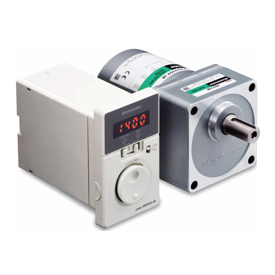
Brushless Motor and Driver Package
BMU
Series
200 W / 400 W
OPERATING MANUAL
Thank you for purchasing an Oriental Motor product.
This Operating Manual describes product handling procedures and safety precautions.
• Please read it thoroughly to ensure safe operation.
• Always keep the manual where it is readily available.
Advertisement
Table of Contents

Subscribe to Our Youtube Channel
Related Manuals for Oriental motor BMU6200SC Series


Summary of Contents for Oriental motor BMU6200SC Series
- Page 1 HM-5153 Brushless Motor and Driver Package Series 200 W / 400 W OPERATING MANUAL Thank you for purchasing an Oriental Motor product. This Operating Manual describes product handling procedures and safety precautions. • Please read it thoroughly to ensure safe operation. •...
-
Page 2: Table Of Contents
Only qualified and educated personnel should work with the product. Use the product correctly after thoroughly reading the section "1 Safety precautions". The items under contain important handling instructions that the user should observe to Note ensure safe use of the product. is described in the related handling items. -
Page 3: Safety Precautions
Safety precautions 1 Safety precautions The precautions described below are intended to prevent danger or injury to the user and other personnel through safe, correct use of the product. Please read and understand these precautions thoroughly before using the product. Handling the product without observing the instructions that accompany a “Warning”symbol Warning may result in serious injury or death. - Page 4 Safety precautions Caution General • Do not use the motor (gearhead) and driver beyond the specifications. Doing so may result in fire, electric shock, injury or damage to equipment. • Do not insert an object into the openings in the driver. Doing so may result in fire, electric shock or injury. •...
-
Page 5: Precautions For Use
Precautions for use 2 Precautions for use This chapter covers limitations and requirements the user should consider when using the product. • Connect protective devices to the power line Connect a circuit breaker or earth leakage breaker to the driver’s power line to protect the primary circuit. If an earth leakage breaker is to be installed, use one incorporating high-frequency noise elimination measures. -
Page 6: Preparation
Preparation 3 Preparation This chapter explains the items you should check, as well as the names and functions of each part. 3.1 Checking the product Verify that the items listed below are included. Report any missing or damaged items to the branch or sales office from which you purchased the product. -
Page 7: Names And Functions Of Parts
Preparation „ Round shaft type in the model name indicates A (no machining) or AC (shaft flat) for the round shaft type. Degree of Output protection of Power supply voltage Model Motor model Driver model power the motor Single-phase 100-120 V BMU5200A-„... -
Page 8: Installation
Installation 4 Installation This chapter explains the installation location and installation methods of the motor and driver, as well as how to install a load. 4.1 Installation location Install the motor in a well-ventilated place where they can be inspected easily and the following conditions are satisfied: [Common conditions] [Degree of protection: IP65 rated motor] •... -
Page 9: X84; Removing/Installing The Gearhead
Installation „ Removing/Installing the gearhead See the following steps to replace the gearhead or to change the cable position. 1. Removing the gearhead Remove the hexagonal socket head screws assembling the motor and gearhead and detach the motor from the gearhead. • Assembly hexagonal socket head screw Model Screw size Tightening torque... -
Page 10: X84; Installing A Load
Installation „ Installing a load When installing a load on the motor (gearhead), pay attention to the following points. • Align the centerline of the motor output shaft (gearhead output shaft) with the centerline of the load. • A key slot is provided on the output shaft of each combination type ∙ parallel shaft gearhead. Form a key slot on the load side and secure the load using the supplied parallel key. -
Page 11: Installing The Driver
Installation 4.3 Installing the driver The driver is designed so that heat is dissipated via air convection and conduction through the enclosure. There must be a clearance of at least 25 mm (0.98 in.) and 50 mm (1.97 in.) clearances in the horizontal and vertical directions, respectively, between the driver and enclosure or other equipment within the enclosure. -
Page 12: Connection
Connection 5 Connection This chapter explains how to connect the driver and motor, I/O signals, and power supply, as well as the grounding method. 5.1 Connecting the power supply The connection varies depending on the power supply voltage of the product. Connect the power supply cable to the CN1 as shown in the figure. -
Page 13: Connecting The Motor
Connection 5.2 Connecting the motor Connect the motor connector (white) of the motor cable to the CN2, and the sensor connector (black) to the CN3 on the driver. Check the pin assignment on p.38. Use a connection cable (supplied or accessory) when extending the wiring distance between the motor and driver. The connection cable can be connected up to 2 pieces. - Page 14 Connection „ CN4 pin assignment Pin No. Signal name Function* Description [ALARM-RESET] This signal is used to reset the alarm. [M1] This signal is used to select the operation data. [M0] The motor rotates in the reverse [REV] direction while this signal is being "ON." The motor rotates in the forward [FWD] direction while this signal is being "ON."...
-
Page 15: Connection Example
Connection 5.5 Connection example „ Connection example for when using switches and relays This is a connection example when the motor is operated using contact switches such as switches and relays. (Single-phase 200-240 VAC) Driver Main circuit Motor connection Motor connector Circuit breaker Power supply Motor connection Driver ground Sensor Motor ground Control circuit... -
Page 16: X84; Connection Example For I/O Signals And Programmable Controller
Connection „ Connection example for I/O signals and programmable controller This is a connection example when the motor is operated using a transistor output type programmable controller. • Sink logic Programmable controller Driver 24 VDC IN-COM0 6.6 kΩ 820 Ω 6.6 kΩ 820 Ω 6.6 kΩ 820 Ω 6.6 kΩ... -
Page 17: Operating By Front Panel
Operating by front panel 6 Operating by front panel This section explains how to operate the product with ease at the factory setting when receiving the product. 6.1 Connecting Black Sensor connector of the motor: Connect the connector to the White Motor connector of the motor: Connect the connector to the Power supply Connect the connector... -
Page 18: Operating
Operating by front panel 6.3 Operating After turning on the power, operate the product as follows. To decelerate and stop To start running the motor the motor To adjust the motor rotation To determine the setting speed of the motor rotation speed ①... -
Page 19: Operating By Programmable Controller
Operating by programmable controller 7 Operating by programmable controller The motor can be operated and stopped externally. AC power supply Programmable Connection: p.12 Motor Driver controller 7.1 Operating After connecting the operation input signals (FWD input, REV input) to the CN4, set and operate the product as follows. - Page 20 Operating by programmable controller • When the setting is "ON" Operation by switches on the front panel: Enable When turning the operation input signal ON while the operation switch is set to the RUN side, the motor rotates. When the operation switch is set to the "STAND-BY" side, the motor decelerates to a stop even if the operation input signal is being ON.
-
Page 21: Operating With Multiple Speeds
Operating by programmable controller 7.2 Operating with multiple speeds The operation at a speed of two or more can be performed by switching the external input. „ Data setting method [Example: Set the rotation speed to 3000 r/min (change from 50 r/min)] Power ON : Setting dial : MODE key : FUNCTION key Panel display Setting the Press two times rotation speed... -
Page 22: Switching The Motor Rotation Direction
Operating by programmable controller 7.3 Switching the motor rotation direction When turning the FWD input or REV input ON, the motor rotation direction varies depending on the state of the rotation direction switch. The rotation direction shown in the figure below is as viewed from the motor output shaft. External operation input Rotation direction switch FWD input... -
Page 23: Convenient Functions
Convenient functions 8 Convenient functions 8.1 Functions list The following functions are available for this product. Reference Functions Description page Displays the rotation speed of the motor output shaft. Rotation speed 28, 26 Displays by converting the motor rotation speed into the rotation speed of the gearhead output shaft. -
Page 24: Setting Items And Panel Displays
Convenient functions 8.2 Setting items and panel displays Top screen Monitor mode Data mode Power ON Rotation Operation Rotation speed data No.0 speed 0 Data setting Speed setting (blinking display) Load factor Acceleration time 0 Data setting Operation data No. Deceleration time 0 Data setting Alarm Alarm record 1 Initialize... - Page 25 Convenient functions When the front panel is removed Explanation of graphic symbols Turn Press the setting dial the MODE key The characters on the black screen represents Press Press the setting dial the FUNCTION key the indication on the display. Parameter mode Return to the "monitor mode"...
-
Page 26: Parameter List
Convenient functions 8.3 Parameter list Operation mode: Parameter mode Factory Item Display Description Setting range setting Sets the speed reduction ratio relative to the rotation speed of the motor output shaft. Displays the speed calculated based on the speed Gr-r Speed reduction ratio reduction ratio on the monitor mode. - Page 27 Convenient functions Factory Item Display Description Setting range setting ---- Not used OUT0 output function AL-1 ALARM-OUT1 oUt0 selection Sp SPEED-OUT Assigns the output signals to the AL-2 ALARM-OUT2 external output terminals. ~ n ouE MOVE OUT1 output function oUt1 AL-1 uA selection...
-
Page 28: Items Displayed On The Driver
Convenient functions 8.4 Items displayed on the driver Operation mode: Monitor mode Item Display Description • Monitors the rotation speed of the motor. • Monitors the rotation speed of the gear output shaft or conveyor transfer speed Rotation speed* when the "speed reduction ratio" parameter is set. •... -
Page 29: Setting The Operation Data
Convenient functions • Display the conveyor transfer speed To display the conveyor transfer speed, calculate the conveyor speed reduction ratio by using the formula below and set to the "speed reduction ratio" parameter. Gearhead gear ratio Conveyor speed reduction ratio = Pulley diameter [m] ×... -
Page 30: Setting The Acceleration Time And Deceleration Time
Convenient functions 8.6 Setting the acceleration time and deceleration time The acceleration time and deceleration time can be set so that an impact is not applied to a load when the motor is started or stopped. There are the following two methods to set. The setting by the "acceleration/deceleration time potentiometer" is enabled at the time of shipment. -
Page 31: Data Locking For The Set Data
Convenient functions 8.7 Data locking for the set data The data setting can be locked so that the set Setting rotation speed does not change. Panel display The setting of data and parameters cannot be Power ON changed using the setting dial while locking. Remove the front panel to set. Press the [MODE] key once. -
Page 32: Holding A Load At Motor Standstill
Convenient functions 8.9 Holding a load at motor standstill If the "slight position-keeping selection" parameter is set to ON (enable), the holding torque is somewhat generated when the motor stops (slight position-keeping torque). The factory setting is OFF (disable). Refer to p.24 or p.26 for how to change the parameter. •... -
Page 33: Alarms And Warnings
Alarms and warnings 9 Alarms and warnings The driver provides alarms that are designed to protect the driver from overheating, poor connection, error in operation, etc. (protective functions), as well as warnings that are output before the corresponding alarms generate (warning functions). 9.1 Alarms If a protective function is activated and an alarm is generated, the motor will coast to a stop, and then the holding power of the motor output shaft is lost. - Page 34 Alarms and warnings „ Alarm reset Always reset an alarm after ensuring safety by removing the cause of the alarm and turning the operation signal OFF. [How to reset the alarm] • Turn the ALARM-RESET input to ON and then OFF. (The alarm will be reset at the OFF edge of the input.) •...
-
Page 35: Warnings
9.2 Warnings The warning types and records can be displayed on the monitor mode. When a warning generates, the WNG output will be turned ON. The WNG output is not assigned to the output terminal at the time of shipment. Refer to p.27 "Description of I/O signals." „... -
Page 36: Troubleshooting And Remedial Actions
Troubleshooting and remedial actions 10 Troubleshooting and remedial actions During motor operation, the motor or driver may fail to function properly due to an improper speed setting or wiring. When the motor cannot be operated correctly, refer to the contents provided in this section and take appropriate action. If the problem persists, contact your nearest office. -
Page 37: Inspection
Inspection 11 Inspection It is recommended that periodic inspections for the items listed below are conducted after each operation of the motor. If an abnormal condition is noted, discontinue any use and contact your nearest Oriental Motor sales office. Note • Perform the insulation resistance test or dielectric strength test separately on the motor and the driver. -
Page 38: Accessories (Sold Separately)
Accessories (sold separately) 12 Accessories (sold separately) „ Connection cable This cable is used to extend the wiring distance between the driver and motor. The wiring distance between the motor and driver can be extended to a maximum of 10.5 m (34.4 ft.). Flexible connection cables are also available. The motor cables, connection cables and flexible connection cables are shielded cables which have taken measures against the electrical noise. -
Page 39: Reference
Reference 13 Reference 13.1 Standard and CE Marking This product is affixed the CE Marking under the Low Voltage Directive and EMC Directive. Some products are recognized by UL under the UL/CSA standards. The name of products certified to conform with relevant standards are represented by applicable unit model motor and driver part numbers. Output power Power supply voltage UL/CSA Standards... -
Page 40: Installing And Wiring In Compliance With Emc Directive
Reference „ Hazardous substances The products do not contain the substances exceeding the restriction values of RoHS Directive (2011/65/EU). Republic of Korea, Radio Waves Act. (200 W·Single-phase/Three-phase 200-240 V input type only) Seller and user shall be noticed that this equipment is suitable for electromagnetic equipments for office work (Class A) and it can be used outside home. - Page 41 Reference „ Wiring the power supply cable Use a shielded cable of AWG18 to 14 (0.75 to 2.0 mm ) in diameter for the driver power supply cable and keep it as short as possible. Strip a part of the shielded cable and ground the stripped part using a metal cable clamp that contacts the stripped cable around its entire circumference, or use a drain wire to make the ground connection.
-
Page 42: Specifications
Reference 13.3 Specifications • o in the model names indicates a number representing the gear ratio. • „ indicates the cable length (-1, -2, -3) when the connection cable is supplied. • in the model name indicates A (no machining) or AC (shaft flat) for the round shaft type. Combination type •... - Page 43 −43−...
- Page 44 • Please contact your nearest Oriental Motor o ce for further information. Singapore Korea Technical Support Tel:(800)468-3982 Tel:1800-8420280 Tel:080-777-2042 8:30 to 5:00 , P.S.T. (M-F) A.M. P.M. www.orientalmotor.com.sg www.inaom.co.kr 7:30 to 5:00 , C.S.T. (M-F) A.M. P.M. www.orientalmotor.com Tel:1800-806161 Hong Kong Branch Tel:+55-11-3266-6018 www.orientalmotor.com.my...
Need help?
Do you have a question about the BMU6200SC Series and is the answer not in the manual?
Questions and answers