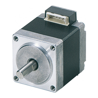
Oriental motor CRK Series Operating Manual

Oriental motor CRK Series Operating Manual

5-phase stepping motor unit
Hide thumbs Also See for CRK Series:

Advertisement

5-Phase Stepping Motor Unit
CRK
OPERATING MANUAL
Thank you for purchasing an Oriental Motor product.
This Operating Manual describes product handling procedures and safety precautions.
Please read it thoroughly to ensure safe operation.
Always keep the manual where it is readily available.

Table of contents

1 Introduction .................................. 2
2 Safety precautions ....................... 4
3 Precautions for use ...................... 7
4 Preparation................................. 10
4.1
Checking the product ................ 10
4.2
drivers ....................................... 10
4.3
5 Installation .................................. 15
5.1
Location for installation ............. 15
5.2
Installing the motor.................... 15
5.3
Installing a load ......................... 17
5.4
permissible thrust load .............. 17
5.5
Installing the driver.................... 19
5.6
with EMC Directive.................... 21
Series
6 Connection..................................24
6.1
Connection example................. 24
6.2
connector housings .................. 27
6.3
6.4
6.5
Timing chart.............................. 33
7 Setting.........................................34
7.1
Step angle ................................ 34
7.2
Pulse input modes.................... 36
7.3
Smooth drive function............... 36
7.4
Motor current ............................ 37
8 Inspection....................................42
actions ........................................43
HP-4189-2

Advertisement

Table of Contents
loading

Summary of Contents for Oriental motor CRK Series

  • Page 1: Table Of Contents

    HP-4189-2 5-Phase Stepping Motor Unit Series OPERATING MANUAL Thank you for purchasing an Oriental Motor product. This Operating Manual describes product handling procedures and safety precautions. Please read it thoroughly to ensure safe operation. • • Always keep the manual where it is readily available.
  • Page 2: Introduction

    Overview of the product The CRK series is a unit product comprised of an open-case microstep driver equipped with smooth drive function and a five-phase stepping motor or various geared motors designed for high torque and low vibration. The smooth drive...
  • Page 3 1 Introduction • For Low Voltage Directive This product is not subject to the EC’s Low Voltage Directive because its input power supply voltage is 24 VDC. However, the user is advised to perform the following actions when conducting product installation and connection. •...
  • Page 4: Safety Precautions

    2 Safety precautions 2 Safety precautions The precautions described below are intended to prevent danger or injury to the user and other personnel through safe, correct use of the product. Use the product only after carefully reading and fully understanding these instructions. Handling the product without observing the instructions Warning that accompany a “Warning”...
  • Page 5 2 Safety precautions Operation • Turn off the driver power supply in the event of a power failure, or the motor may suddenly start when the power is restored and may cause injury or damage to equipment. • Do not turn the A.W.OFF (All windings off) input to “ON” while the motor is operating.
  • Page 6 2 Safety precautions Operation • Use a motor and driver only in the specified combination. An incorrect combination may cause a fire. • Provide an emergency-stop device or emergency-stop circuit external to the equipment so that the entire equipment will operate safely in the event of a system failure or malfunction.
  • Page 7: Precautions For Use

    3 Precautions for use 3 Precautions for use This section covers limitations and requirements the user should consider when using the CRK series. • Conduct the insulation resistance measurement or withstand voltage test separately on the motor and the driver.
  • Page 8 3 Precautions for use • Geared type motors Backlash The TH gear output shaft is subject to backlash of 10 to 60 minutes. As for the PL gear output shaft is subject to backlash of 15 to 35 minutes. As for the PN gear output shaft is subject to backlash of 2 to 3 minutes.
  • Page 9 3 Precautions for use • About regeneration When a large inertial load is operated at high speed, regenerative energy will generate and increase the power supply voltage, which can damage the driver. Review the operating condition and make sure regenerative voltage will not generate.
  • Page 10: Preparation

    4 Preparation 4 Preparation This section covers the points to be checked along with the names and functions of the respective parts. 4.1 Checking the product Upon opening the package, verify that the items listed below are included. Report any missing or damaged items to the branch or sales office from which you purchased the product.
  • Page 11 4 Preparation High-torque type Unit model Motor model Driver model Single shaft Double shaft Single shaft Double shaft CRK513PAP CRK513PBP PK513PA PK513PB CRK523PAP CRK523PBP PK523PA PK523PB CRD5103P CRK525PAP CRK525PBP PK525PA PK525PB CRK544PAP CRK544PBP PK544PA PK544PB CRD5107P CRK546PAP CRK546PBP PK546PA PK546PB Standard type Unit model Motor model...
  • Page 12 4 Preparation PL geared type Unit model Motor model Driver model Single shaft Double shaft Single shaft Double shaft CRK545AP-P5 CRK545BP-P5 PK545AW-P5 PK545BW-P5 CRK545AP-P7.2 CRK545BP-P7.2 PK545AW-P7.2 PK545BW-P7.2 CRK545AP-P10 CRK545BP-P10 PK545AW-P10 PK545BW-P10 CRD5107P CRK543AP-P25 CRK543BP-P25 PK543AW-P25 PK543BW-P25 CRK543AP-P36 CRK543BP-P36 PK543AW-P36 PK543BW-P36 CRK543AP-P50 CRK543BP-P50 PK543AW-P50...
  • Page 13: Names And Functions Of Parts

    4 Preparation Harmonic geared type Unit model Motor model Driver model Single shaft Double shaft Single shaft Double shaft CRK543AP-H50 CRK543BP-H50 PK543AW-H50S PK543BW-H50S CRD5107P CRK543AP-H100 CRK543BP-H100 PK543AW-H100S PK543BW-H100S CRK564AP-H50 CRK564BP-H50 PK564AW-H50S PK564BW-H50S CRD5114P CRK564AP-H100 CRK564BP-H100 PK564AW-H100S PK564BW-H100S 4.3 Names and functions of parts This section covers the names and functions of parts in the motor and driver.
  • Page 14 4 Preparation Driver CRD5103P, CRD5107P, CRD5114P Mounting holes MOSFET arrays Mounting holes Mounting holes 1. Power supply connector (CN1) [P.26] Connect to a 24 VDC power supply. 2. I/O signals connector (CN2) [P.26] Connect to I/O signals. 3. Motor connector (CN3) [P.26] Connect to motor leads.
  • Page 15: Installation

    5 Installation 5 Installation This chapter explains the installation location and installation methods of the motor and driver, as well as how to install a load. The installation and wiring methods in compliance with the EMC Directive are also explained. 5.1 Location for installation The motor and driver are designed and manufactured for installation in equipment.
  • Page 16 5 Installation Bolt size, tightening torque and installation method Motor model Tightening Effective Bolt Installation torque depth of bolt size method Single shaft Double shaft [N·m (oz-in)] [mm (in.)] PK513PA PK513PB 0.25 (35) PK523PA PK523PB PK525PA PK525PB 2.5 (0.098) PK523PMA PK523PMB M2.5 0.5 (71)
  • Page 17: Installing A Load

    5 Installation 5.3 Installing a load When connecting a load to the motor, align the centers of the motor’s output shaft and load shaft. Also, keep the overhang load and thrust load to the permissible values or below. Using a coupling Align the centers of the motor’s output shaft and load shaft in a straight line.
  • Page 18 5 Installation Permissible overhung load and permissible thrust load Permissible overhung load [N (lb.)] Motor model Permissible Distance from the tip motor’s output shaft [mm (in.)] thrust load [N (lb.)] Single shaft Double shaft (0.20) (0.39) (0.59) (0.79) 0.05 PK513PA PK513PB ∗...
  • Page 19: Installing The Driver

    5 Installation Permissible overhung load [N (lb.)] Motor model Permissible Distance from the tip motor’s output shaft [mm (in.)] thrust load [N (lb.)] Single shaft Double shaft (0.20) (0.39) (0.59) (0.79) PK544AW-N PK544BW-N 100 (22) (22) (27) (33) (42) PK566AW-N5 PK566BW-N5 100 (22) (45)
  • Page 20 5 Installation • Horizontal installation CRD5103P, CRD5107P, CRD5114P M3 screws Spring washers Metal plate Spacers (insulation) • Vertical installation CRD5103P, CRD5107P, CRD5114P Spacers (insulation) Metal plate Spring washers M3 screws There must be a clearance of at least 25 mm (0.98 in.) and 50 mm (1.97 in.) in the horizontal and vertical directions, respectively, between the driver and enclosure or other equipment.
  • Page 21: Installing And Wiring In Compliance With Emc Directive

    Failure to do so may result in serious impairment of the machine’s functionality. The use of the following installation and wiring methods will enable the CRK series motor and/or driver to be compliant with the EMC Directive. Oriental Motor conducts EMC measurement of its CRK series motors and drivers in accordance with “Example of motor and driver installation and wiring”...
  • Page 22 5 Installation Mains filter Connect a mains filter on the input side of the DC power supply so as to prevent the noise generated in the driver from being transmitted externally via the power supply line. When a power supply transformer is used, be sure to connect a mains filter on the AC input side of the power supply transformer.
  • Page 23 5 Installation Notes about installation and wiring • Connect the motor, driver and any surrounding control system equipment directly to the grounding point so as to prevent a potential difference from generating between grounds. • When relays or electromagnetic switches are used together with the system, use mains filters and CR circuits to suppress surges generated by them.
  • Page 24: Connection

    6 Connection 6 Connection This section covers the methods of connecting the driver, motor, power supply and controller, as well as the connection examples and I/O signals. The motors of the high-resolution types, high-torque types and geared types (CRK523P) use a motor leads connector connection system. Use the supplied motor cable.
  • Page 25 6 Connection PNP-type Driver 24 VDC±10% Connector terminal number Lead color Blue Orange Green Black Controller (+5 to 24 VDC) 220 Ω (CW) 220 Ω DIR. (CCW) 220 Ω A.W.OFF 220 Ω 220 Ω C.D.INH (+5 to 24 VDC) TIMING Note Use 5 VDC as input signal voltage.
  • Page 26 6 Connection Connector pin assignments for driver Connector No. Pin No. Type Signal Description Input +24 VDC POWER Input Input Pulse input (CW) (CW pulse) Input Input DIR. Rotation direction (CCW) input (CCW pulse) Input Input A.W.OFF All windings off input Input Input Step angle select...
  • Page 27: Suitable Contacts And Connector Housings

    6 Connection Connector pin assignments for connector-type motor Terminal Motor-leads Blue Orange Green Black color 5 4 3 2 1 When disconnecting the connector-type motor cable, pull the connector Note horizontally along the output shaft to remove. The motor may be damaged if force is applied in any other direction.
  • Page 28 6 Connection Connector housing, contact and crimping tool for driver (Molex) CRD5103P, CRD5107P, CRD5114P Driver model For power Connector housings 51103-0200 supply Contacts 50351-8100 connection Specified crimping tool 57295-5000 Connector housings 51103-1200 Contacts 50351-8100 I/O signals Specified crimping tool 57295-5000 Connector housings 51103-0500 For motor...
  • Page 29: Connecting The Power Supply

    6 Connection Connector housing, contact and crimping tool for motor (Molex) PK513P PK54 P PK52 P PK56 PM Motor type PK54 PM PK52 PM Connector housings 51065-0500 51103-0500 51144-0500 Contacts 50212-8100 50351-8100 50539-8100 Specified crimping tool 57176-5000 57295-5000 57189-5000 Note When connecting a connector-type motor, affix the cable at the connection part to prevent the connection part from receiving stress due to the flexing of the cable.
  • Page 30 6 Connection When the DIR. input is “ON,” a fall of the pulse input from “ON” to “OFF” will rotate the motor one step in the CW direction. When the DIR. input is “OFF,” a fall of the pulse input from “ON” to “OFF”...
  • Page 31 6 Connection 90 % CW input 10 % 1 µs 1 µs or more or more 2 µs 2 µs or less or less 10 µs or more CCW input Maintain driver temperature so that the surface temperature of the Note •...
  • Page 32 6 Connection Output signals The driver’s output signals are photocoupler/open-collector outputs. The signal states indicate the state of the internal photocoupler (ON: power conducted; OFF: power not conducted). • TIMING (excitation timing) output When the motor-excitation state (combined phases of current flowing) is the excitation home position (step [0]), the driver switches on the timing output.
  • Page 33: Timing Chart

    6 Connection 6.5 Timing chart Motor operation ∗4 5 s or more 0.5 s or more Power supply input ∗1 ∗1 ∗3 300 µs or more 10 µs or more 10 µs or more 1-pulse input PLS input DIR. input 2-pulse input CW input ∗1...
  • Page 34: Setting

    7 Setting 7 Setting 7.1 Step angle When setting the motor’s step angle, use the step angle setting switches (DATA1, DATA2) and the resolution select switches (R1, R2). Factory settings: R1 Resolution select switch ー ー With each of the two switches, step angles can be preset in 16 steps and a desired setting can be selected through C/S (step angle switching) input.
  • Page 35 7 Setting The table below applies to motors with a base step angle of 0.72°/step. The step angle is calculated by dividing the base step angle by the number of divisions. Number Number DATA1 Resolution Step DATA1 Resolution Step DATA2 divisions angle 1 DATA2...
  • Page 36: Pulse Input Modes

    7 Setting 7.2 Pulse input modes Either the 1-pulse or 2-pulse input mode may be selected in accordance with the controller used. Pulse input mode select switch ー ー • When the motor is to be controlled through the pulse signal and the rotation direction signal that specifies the motor’s direction of rotation, set the pulse input mode select switch to “1P.”...
  • Page 37: Motor Current

    7 Setting Factory setting: [SD: Smooth drive abled] Smooth drive function select switch ー ー • When the smooth drive function is used • When the smooth drive function is not used Note The smooth drive function does not work if the step angle is set to a ∗...
  • Page 38 7 Setting Setting the motor operating current Connect a DC ammeter between the motor and driver. Turn the C.D.INH (current cutback release) input to “ON.” Do not apply other input signals. Turn on the driver’s power supply (24 VDC). Driver +24 VDC Current cutback release signal...
  • Page 39 7 Setting When the motor operating current potentiometer (RUN) is turned counterclock wise, the current decreases. CRD5103P CRD5107P [Representative values] [Representative values] 0.75 A/phase 0.35 A/phase (Factory setting) (Factory setting) RUN potentiometer RUN potentiometer CRD5114P [Representative values] 1.4 A/phase (Factory setting) RUN potentiometer The scale values are not displayed on the control.
  • Page 40 7 Setting Setting current at motor standstill The current at motor standstill is factory set so that it will be about 50% of the motor’s operating current (This proportion does not change, even if the motor’s operating current is changed). When changing the setting of current at motor standstill, use the motor stop current potentiometer (STOP).
  • Page 41 7 Setting When the setting is complete, turn off the power supply. After about 0.1 sec. has passed since the pulse was stopped, the motor’s operating current automatically decreases to the set value of current at motor standstill. Note Set the motor’s operating current to a value not exceeding the rated •...
  • Page 42: Inspection

    8 Inspection 8 Inspection It is recommended that periodic inspections be conducted for the items listed below after each operation of the motor. If an abnormal condition is noted, stop the use and contact your nearest office. Inspection items • Are the motor installation screws loose? •...
  • Page 43: Troubleshooting And Remedial Actions

    9 Troubleshooting and remedial actions 9 Troubleshooting and remedial actions During motor operation, the motor or driver may fail to function properly due to an improper speed setting or wiring. When the motor cannot be operated correctly, refer to the contents provided in this section and take appropriate action. If the problem persists, contact your nearest office.
  • Page 44 9 Troubleshooting and remedial actions Phenomenon Possible cause Remedial action Motor operation is Check the controller and Pulse input line connection • unstable. driver connections. error • Check the pulse input specifications (voltage and width). Slow motor start Effect of the smooth drive Disable the smooth drive (self-starting operation) function...
  • Page 45 9 Troubleshooting and remedial actions Phenomenon Possible cause Remedial action Current does not drop The current cutback release Switch current cutback when the motor stops. input is set to “ON” release input to “OFF.” CW input, CCW input or PLS After the pulses stop, always input set to “ON”...
  • Page 46: Options (Sold Separately)

    10 Options (Sold separately) 10 Options (Sold separately) Motor cable The lead wires come preassembled with a crimped connector for easy connection of a connector-type motor. ∗ Unit models come standard with a 0.6 m (2 ft.) motor cable. Model Length Applicable product LC5N06A...
  • Page 47 10 Options (Sold separately) Motor connector set (Molex) A set of connector housings and contacts matching a connector-type motor. Each bag contains enough housings and contacts for connecting 30 motors. Applicable Connector Model Contacts Applicable cable motor housings ∗ CS5N30A PK513P 51065-0500 50212-8100 AWG30 to 24...
  • Page 48 The third-party products mentioned in this manual are recommended products, and references to their names shall not be construed as any form of performance guarantee. Oriental Motor is not liable whatsoever for the performance of these third-party products. © Copyright ORIENTAL MOTOR CO., LTD. 2006 •...

This manual is also suitable for:

Crk523pmapCrk523pmbpPk523pmbCrk524pmapCrk524pmbpPk524pma ... Show all

Table of Contents