Table of Contents
Advertisement
Quick Links
ユニットタイプスピードコントロールモーター
USシリーズ
●110V/115Vタイプ
●220V/230Vタイプ
取扱説明書
C
English version follows Japanese version.
お買い上げいただきありがとうございます。
この取扱説明書には、製品の取り扱いかたや安全上の注意事項を示しています。
・取扱説明書をよくお読みになり、製品を安全にお使いください。
・お読みになったあとは、いつでも見られるところに必ず保管してください。
1.安全上のご注意.................................................2ページ
2.現品到着時の確認 .............................................4ページ
3.取り付け ...........................................................6ページ
4.接続.................................................................11ページ
5.運転.................................................................12ページ
6.特性.................................................................15ページ
7.拘束時のモーター焼損保護について ..............15ページ
8.正常に動作しない場合のチェックポイント ...16ページ
もくじ
HM-9164-2
Advertisement
Chapters
Table of Contents

Subscribe to Our Youtube Channel
Related Manuals for Oriental motor US Series


Summary of Contents for Oriental motor US Series
-
Page 1: Table Of Contents
HM-9164-2 ユニットタイプスピードコントロールモーター USシリーズ ●110V/115Vタイプ ●220V/230Vタイプ 取扱説明書 English version follows Japanese version. もくじ 1.安全上のご注意..........2ページ 2.現品到着時の確認 ..........4ページ 3.取り付け ............6ページ 4.接続..............11ページ 5.運転..............12ページ 6.特性..............15ページ 7.拘束時のモーター焼損保護について ....15ページ 8.正常に動作しない場合のチェックポイント ...16ページ お買い上げいただきありがとうございます。 この取扱説明書には、製品の取り扱いかたや安全上の注意事項を示しています。 ・取扱説明書をよくお読みになり、製品を安全にお使いください。 ・お読みになったあとは、いつでも見られるところに必ず保管してください。... -
Page 2: 1.安全上のご注意
1.安全上のご注意 製品の取り扱いは、適切な資格を有する人が行なってください。 お使いになる前に、 「安全上のご注意」をよくお読みのうえ、製品を正しくお使いください。 ここに示した注意事項は、製品を安全に正しくお使いいただき、お客様や他の人々への危害や損傷を未然に防止するためのもの です。内容をよく理解してから製品をお使いください。 警告 この警告事項に反した取り扱いをすると、死亡または重傷を負う場合がある内容を示しています。 注意 この注意事項に反した取り扱いをすると、損害を負うまたは物的損害が発生する場合がある内容を示しています。 重要 製品を正しくお使いいただくために、お客様に必ず守っていただきたい事項を本文中の関連する取り扱い項目に記載しています。 警告 全般 ● 爆発性雰囲気、引火性ガスの雰囲気、腐食性の雰囲気、水のかかる場所、可燃物のそばでは使用しないでください。 火災・感電・けがの原因になります。 ● 接地、接続、運転・操作、点検・故障診断の作業は、適切な資格を有する人が行なってください。 火災・感電・けがの原因になります。 ● 通電状態で移動、設置、接続、点検の作業をしないでください。電源を切ってから作業してください。 感電の原因になります。 ● モーターの過熱保護装置(サーマルプロテクタ)がはたらいたときは、電源を切ってください。過熱保護装置が自動復帰した ときにモーターが突然起動して、けが・装置破損の原因になります。 設置 ● モーターはクラス 機器のみに使用してください。感電の原因になります。 ● モーターは筐体内に設置してください。感電・けがの原因になります。 ● 設置するときは、モーター、コントロールユニットに手が触れないようにするか、接地してください。感電の原因になります。 接続 ● コントロールユニットの電源入力電圧は、定格値を必ず守ってください。火災・感電の原因になります。 ● 接続は接続図にもとづき、確実に行なってください。火災・感電の原因になります。 ● ケーブルを無理に曲げたり、引っ張ったり、はさみ込んだりしないでください。火災・感電の原因になります。 ●... - Page 3 注意 全般 ● モーター、コントロールユニットの仕様値を超えて使用しないでください。感電・けが・装置破損の原因になります。 ● モーターの開口部に指や物を入れないでください。火災・感電・けがの原因になります。 ● 運転中および停止後しばらくの間は、モーターに触れないでください。モーターの表面が高温のため、やけどの原因になり ます。 運搬 ● モーター出力軸、モーターケーブルを持たないでください。けがの原因になります。 設置 ● モーター、コントロールユニットの周囲には、可燃物を置かないでください。火災・やけどの原因になります。 ● モーター、コントロールユニットの周囲には、通風を妨げる障害物を置かないでください。装置破損の原因になります。 ● モーターは金属板に確実に固定してください。けが・装置破損の原因になります。 ● モーターの回転部(出力軸)に、カバーを設けてください。けがの原因になります。 接続 ● 漏電遮断機を設置してください。火災の原因になります。 運転 ● モーターとコントロールユニットは、指定された組み合わせで使用してください。火災の原因になります。 ● 装置の故障や動作の異常が発生したときは、装置全体が安全な方向へはたらくよう非常停止装置、または非常停止回路を外部 に設置してください。けがの原因になります。 ● 異常が発生したときは、ただちに運転を停止して、ドライバの電源を切ってください。火災・感電・けがの原因になります。 ● 電源を投入するときは、コントロールユニットのRUN/STAND-BYスイッチをSTAND-BY、および回転速度設定器をLOWに 設定してから行なってください。モーターが起動し、けが・装置破損の原因になります。 ● 運転中は回転部(出力軸、冷却ファン)に触れないでください。けがの原因になります。 ● モーターは、正常な運転状態でも、表面温度が70°Cを超えることがあります。運転中のモーターに接近できるときは、図の 警告ラベルをはっきり見える位置に貼ってください。やけどの原因になります。 警告ラベル...
-
Page 4: 2.現品到着時の確認
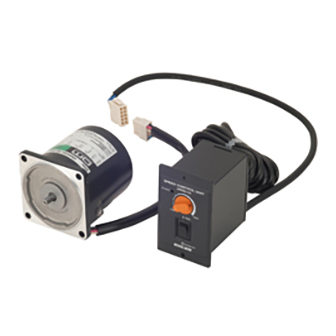
2.現品到着時の確認 2.1 現品の確認 以下のものがすべて揃っているか確認してください。 もし、不足している場合や破損している場合は、最寄りの支店・営業所にご連絡ください。 ・モーター ・・・・・・・・・・・・・・・・・・・・・・・・・・・・・・・・・・1台 ・コントロールユニット ・・・・・・・・・・・・・・・・・・・・・・1台 ・コントロールユニット取付用M3ねじセット ・・・1 ねじ ・・・・・・・・・・・・・・・・・・・・・・・・・・・・・・4個 ワッシャー ・・・・・・・・・・・・・・・・・・・・・・・・4個 ナット ・・・・・・・・・・・・・・・・・・・・・・・・・・・・4個 ・取扱説明書(本書) ・・・・・・・・・・・・・・・・・・・・・・・・・1部 モーターおよびコントロールユニットは下記の規格に従って設計、検査を行ない、認定を取得しています。 認定品名は、モーター品名およびコントロールユニット品名です。 モーター コントロールユニット 認定規格 UL2111, UL1004 UL508 CSA C22.2 No.100, CSA C22.2 No.77 CSA C22.2 No.14 EN60950-1 適合規格 EN60034-1, EN60034-5 EN60950-1 IEC60034-11 (15W〜90Wタイプ), IEC60664-1 EN50178 認定機関 UL File No.E64199 (6Wタイプ) UL File No. E91291 E64197 (15W〜90Wタイプ) 設置条件 設置カテゴリー 、汚損度2、クラス 機器(適用規格 EN/IEC規格) 機器によって設置カテゴリー 、汚損度3の規定値が要求される場合は、モーターおよび... - Page 5 2.2 品名および組み合わせの確認 この製品はモーターとコントロールユニットをセットでお届けしています。 製品がお手元に届きましたら、モーターとコントロールユニットの組み合わせ、およびコンデンサ(内蔵または外付け)の タイプをお確かめください。 ※1 ユニット品名は安全規格認定登録品名ではありません。 安全規格の認定は、モーター品名およびコントロールユニット品名でそれぞれ取得しています。 ※2 適合ギヤヘッド品名の□には、減速比の数字が入ります。 ■110V/115Vタイプ 適合ギヤヘッド品名 ※2 ユニット品名 ※1 コンデンサのタイプ モーター品名 コントロールユニット品名 (別売) US206-401U USM206-401W 2GN□K USP206-1U US206-001U USM206-001W US315-401U USM315-401W 3GN□K USP315-1U US315-001U USM315-001W 内蔵 4GN□K, 4GN□RH, 4GN□RA US425-401U USM425-401W USP425-1U US425-001U USM425-001W US540-401U USM540-401W 5GN□K, 5GN□RH, 5GN□RA USP540-1U...
-
Page 6: 3.取り付け
3. 取り付け 取付条件 モーター、コントロールユニットは以下の条件のところに取り付けてください。 この範囲外で使用すると製品が破損するおそれがあります。 ・屋内(この製品は機器組込用に設計、製造されたものです) ・周囲温度 モーター:-10°C〜+40°C(凍結しないこと) コントロールユニット:0°C〜+40°C(凍結しないこと) ・周囲湿度 85%以下(結露しないこと) ・爆発性ガス、引火性ガス、腐食性ガスがないこと ・直射日光が当たらないこと ・ほこりがかからないこと ・水、油などがかからないこと ・放熱しやすいこと ・連続的な振動、過度の衝撃が加わらないこと ・標高1,000m以下の場所 ・設置カテゴリー 、汚損度2、クラス 機器(適用規格 EN/IEC規格) 機器によって設置カテゴリー 、汚損度3の規定値が要求される場合は、モーターおよびコントロールユニットを IP54相当のキャビネットに収納し、絶縁トランスを介して給電してください。 3.1 モーターの取り付け ■丸シャフトタイプ 取付板にねじ、モーター寸法にあった穴をあけてください。 ねじ、ナット、座金を使用し、モーターを取付板に ナット 固定してください。この時、モーター取付面と取付板に ワッシャ モーター すきまがないようにしてください。 取付板 また、ねじは適切な長さのものを用意して取り付けてください。 取付用ねじ 取付ねじ モーター取付角寸法 ねじサイズ 締付トルク 2.0N·m (20kgfcm) □60mm 2.5N·m (25kgfcm) □70mm 2.5N·m (25kgfcm) □80mm 3.0N·m (30kgfcm) - Page 7 ■冷却ファン付きタイプ 装置 吸込 冷却ファン付きモーターを装置に取り付ける場合には、 モーター後部の冷却用吸込口をふさがないように、 ファンカバーの後ろを10mm以上あけるか、 換気穴をあけてください。 冷却ファンは、モーター運転中常時回転するわけではありません。 モーターへの入力電圧に応じて回転します。 吐出 3.2 コントロールユニットの取り付け コントロールユニットを機器に取り付ける際には、2通りの方法があります。 取り付けは、以下の方法を参考にしてください。 M4のねじは付属しておりませんので、ご用意ください。 重要 ねじの締付トルクは0.7N·m (7kgfcm) 未満としてください。 0.7N·m (7kgfcm) を超えるトルクで締め付けると、コントロールユニットが破損する場合があります。 ■四角い穴をあけて取り付ける方法 左図のように取付板に穴をあけてください。 取付板 2−φ4.5 取付板の前面からコントロールユニットを挿入し、 ねじとナットを用意して固定してください。 取付ねじ、ナット +1 サイズ 数 各2個 2-M4ナット コントロールユニット 2-M4ねじ 取付板 ...
- Page 8 ■四角い穴をあけずに取り付ける方法 左図のように取付板に穴をあけてください。 ±0.2 13.2 取付板 ±0.2 コントロールユニット本体からフロントパネルを (断面図A) φ23 φ7 取り外してください。 (フロントパネルだけを 持って手前に引くと外れます。 ) φ28 4 -φ3.5 2 -φ7.5 付属のM3のねじとナット各4個を使用し、取付板に (断面図A) コントロールユニット本体を固定してください。 2., 3., 4. 以下のねじとナットを用意して、取付板の前面から 4-M3ナット(付属) 2-M4ナット フロントパネルをかぶせて固定してください。 コントロールユニット 取付ねじ、ナット サイズ 数 各2個 4-M3ねじ(付属) 重要 取付板をコントロールユニットと 2-M4ねじ フロントパネルではさみつけるため、 取付板の厚みは2mm以下にしてください。 取付板 ...
- Page 9 3.4 EMC指令に対する設置・配線方法 ■はじめに ◆EMC指令 (89/336/EEC、92/31/EEC) USシリーズは、ユニット品名の末尾が “E” の製品についてEMC指令に適合しています。 USシリーズは、機器組み込み用の部品として設計・製造されています。EMC指令では、この製品が組み込まれたお客様の機械装 置での適合が要求されます。 これからご紹介するモーター/コントロールユニットの設置・配線方法は、お客様の機械装置のEMC指令への適合に有効な基本 的な設置・配線方法について説明したものです。 最終的な機械装置のEMC指令への適合性は、モーター/コントロールユニットと一緒に使用される他の制御システム機器、電気 部 品 の 構 成 、 配 線 、 配 置 状 態 、 危 険 度 な ど に よ っ て 変 わ っ て き ま す の で 、 お 客 様 ご 自 身 で 機 械 装 置 の E M C 試 験 を 行 なって確認していただく必要があります。...
- Page 10 ◆モーターケーブルの接続 モーターケーブルを延長するときは、オプション(別売り)の延長ケーブルを使用してください。 詳細は14ページの「5.5 モーターを遠隔操作する場合」をご覧ください。 ◆その他 ・モーター/コントロールユニットと周辺の制御システム機器のアース間に電位差が生じないように、直接接地ポイントに 接地してください。 ・リレーや電磁スイッチを一緒に使用するときは、ACラインフィルタやCR回路でサージを吸収してください。 ◆モーター、コントロールユニットの接地・配線例 モーター コントロールユニッ ト SPEED CONTROL UNIT USP560-2E POWER HIGH STAND-BY コンデンサ 入力電源 Grounded Panel A : アース用リード線 B : ACラインフィルタ C : 電源ケーブル D : モーターケーブル (4.75 m) ■静電気についての注意事項 静電気によって、コントロールユニットが誤動作したり破損することがあります。コントロールユニットに電源を投入した状態 でのドライバの取り扱いには気をつけてください。 重要 電源を投入した状態のコントロールユニットに近づいたり、触れたりしないでください。...
-
Page 11: 4.接続
4.接続 4.1 接続手順 以下の説明は、出荷時の設定のまま使用する場合です。 回転方向は、モーター出力軸側からみて時計方向に回転するように設定してあります。 回転方向を変える場合は、 「5.運転」の項を参照してください。 ※図は110V/115V コンデンサ外付けタイプです。 緑のアース用リード線を接地して ください。 このアースはノイズ除去用の機能アース です。 モーター部のコネクタと コントロールユニット部のコネクタを 接続してください。このとき、コネクタは 「カチッ」という音がするまで差し込んで、 確実に接続してください。 コントロールユニットの モーター 「RUN/STAND-BY」スイッチが コントロールユニット 「STAND-BY」 、回転速度設定器のツマミが 「LOW」になっていることを確認してから、 電源コードを電源に接続してください。 電源を投入するとコントロールユニットの POWER LED(緑)が点灯します。... -
Page 12: 5.運転
5.運転 重要 ・ このモーターはB種絶縁モーターです。 モーター運転中は、モーターケースの温度が90°Cを超えないことを確認してください。 90°Cを超える温度でモーターを運転すると、巻線、ボールベアリングの寿命を短くします。 モーターケースの温度は、モーター表面に温度計を固定して計測できます。また、サーモテープまたは熱電対を 使用しても計測できます。 ・ 60W、90Wタイプの場合、低速、軽負荷で運転するとモーターの発熱が少ないため、 モーター後部の冷却ファンは回転しない設定になっています。 ・ コントロールユニット内部には、外部からのノイズに対するフィルタを内蔵しておりますが、 ノイズのレベルによっては設定回転速度と異なる回転速度で回るなどの誤動作を招く場合があります。 機器に取り付け後、実機にて確認してください。 誤動作する場合は、ノイズフィルタ、フェライトコアなどを取り付けることにより防止することができます。 ・ コントロールユニットの電源コード端子台のリード線を差し替える場合は、電源をOFFにしてから 行なってください。 5.1 モーターの運転・変速・停止 ■運転 コントロールユニットの「RUN/STAND-BY」スイッチを コントロールユニット正面 「RUN」側に倒します。 回転速度設定器で設定した速度で回転し始めます。 回転速度設定器 POWER LED ■停止 POWER コントロールユニットの「RUN/STAND-BY」スイッチを RUN/STAND-BY 最高速度 スイッチ ... - Page 13 5.2 一方向運転で使用する場合 コントロールユニットのコンデンサが内蔵タイプか外付けタイプかにより接続が異なります。 お求めのタイプがどのタイプかは「2.2 品名および組み合わせの確認」(P.5)の表でご確認ください。 回転方向は、モーター出力軸側から見て時計方向をCW、反時計方向をCCWとしています。 出荷時は時計方向に回転するように設定されているため、電源コード端子台のリード線はN(CW)に接続されています。 反時計方向に回転させる場合は、N(CCW)に接続してください。 ※図は110V/115Vタイプです。 出荷時の設定「CW」を「CCW」に変える場合 ■コンデンサ内蔵タイプ コントロールユニット後部の 電源コード端子台のプラスチックカバーを 外してください。 電源コード端子に接続されている 黒のリード線を、N(CW)からN(CCW)に 差し替えてください。 出荷時は電源コード端子はLとN(CW)に 接続されています。 電源コード端子台にプラスチックカバーを 取り付けてください。 ■コンデンサ外付けタイプ コントロールユニット後部の 電源コード端子台のプラスチックカバーを 外してください。 電源コード端子N(COM),N(CW)に 接続されている黒のリード線を、 N(CW)からN(CCW)に差し替えてください。 その際、コンデンサのリード線(黄色)は 動かさないでください。 出荷時は電源コード端子に接続されている 黒のリード線はN(COM),N(CW)に 接続されています。 電源コード端子台にプラスチックカバーを 取り付けてください。...
- Page 14 5.3 正逆運転する場合 電源用スイッチと正逆転切替スイッチを設けて、回転方向を切り替えてください。 重要 モーターの回転方向の切り替えは、モーターが完全に停止してから行なってください。 回転方向が切り替わらなかったり時間がかかったりする場合があります。 ■コンデンサ内蔵タイプ 電源用スイッチ「SW1」と正逆転切替スイッチ 「SW2」を接続してください。 「RUN/STAND-BY」スイッチをSTAND-BY側に 倒し、モーターが完全に停止するのを AC電源 N(CW) 確認してください。 モーター停止後、電源スイッチ「SW1」を切り、 N(CCW) 「SW2」を切り替えてください。 電源スイッチ「SW1」をON側にしてください。 ■コンデンサ外付けタイプ 電源コード端子台のN(COM),N(CW)に 接続されている黒のリード線を外してください。 . 電源用スイッチ「SW1」と正逆転切替スイッチ AC電源 N(CW) 「SW2」を接続してください。 「RUN/STAND-BY」スイッチをSTAND-BY側に N(COM) 倒し、モーターが完全に停止するのを N(CCW) 確認してください。 モーター停止後、電源スイッチ「SW1」を切り、 「SW2」を切り替えてください。 コンデンサ 電源スイッチ「SW1」をON側にしてください。 ■スイッチの接点容量 AC250V 5A以上の容量のものをお使いください。 5.4 モーターの回転速度を確認する場合 オプションのデジタル表示型回転計SDM496(別売)をご使用ください。 電源コード端子のSPEED OUTを デジタル回転計の 端子に接続してください。 1 、11 デジタル回転計 ...
-
Page 15: 6.特性
6.特性 ■使用限界線について スピードコントロールモーターは、負荷と回転速度に対応して 入力が変わります。負荷が大きいほど、また回転速度が遅いほど 温度上昇は高くなります。 50Hz ACスピードコントロールモーターの回転速度−トルク特性の 60Hz グラフには、図のように「使用限界線」が記入されており、 この斜線部を連続運転領域と言います。 「使用限界線」はモーターの許容最高温度を超えずに連続で 運転できる限界で、モーターの温度から決められます。 60Hz使用限界線 実際の負荷と回転速度で連続で使えるかどうかは、モーターケース 50Hz使用限界線 の温度を測定し判断します。 モーターケース温度90°C以下であれば、 その条件にて連続使用可能です。 ギヤヘッド使用の場合、ギヤヘッドの許容トルク以下のトルクで お使いください。ギヤヘッドを使用して、このトルクを超えて 1000 1500 1800 回転速度[r/min] 運転すると寿命が短くなったり、破損することがあります。 7.拘束時のモーター焼損保護について ●モーターの過熱保護装置(サーマルプロテクタ)がはたらいたときは、電源を切ってください。過熱保護装置が 警告 自動復帰したときにモーターが突然起動して、けが・装置破損の原因になります。 このモーターは、モーターが何らかの原因で異常発熱し、焼損に至るのを防止するための機能を備えています。 保護方式には次の2通りがあります。 ■サーマルプロテクタ方式(モーター銘板に「TP」 「TP211」と記載されています) 規定の温度になると、内蔵サーマルプロテクタが働いてモーターは停止します。 自動復帰型のため、モーターの温度が下がると自動的に運転を再開します。 点検作業は必ず電源を切ってから行なってください。 サーマルプロテクタ動作温度 開(電源を遮断する)………130°C±5°C 閉(電源をつなぐ) ……… 82°C±15°C ■インピーダンスプロテクト方式(モーター銘板に「ZP」と記載されています)... -
Page 16: 8.正常に動作しない場合のチェックポイント
モーターと同じ歯切りタイプのギヤヘッドを組み付けていますか? 負荷を付けずに低速で運転していませんか? 冷却ファンが回転しない 速度設定器のツマミをHIGHにして冷却ファンが回転すれば正常です。 ・この取扱説明書の一部または全部を無断で転載、複製することは、禁止されています。 損傷や紛失などにより、取扱説明書が必要なときは、最寄りの支店または営業所に請求してください。 ・取扱説明書に記載されている情報、回路、機器、および装置の利用に関して産業財産権上の問題が生じても、当社は一切の責任を 負いません。 ・製品の性能、仕様および外観は改良のため予告なく変更することがありますのでご了承ください。 ・取扱説明書には正確な情報を記載するよう努めていますが、万一ご不審な点や誤り、記載もれなどにお気づきの点がありましたら、 最寄りのお客様ご相談センターまでご連絡ください。 ・ は、日本その他の国におけるオリエンタルモーター株式会社の登録商標または商標です。 その他の製品名、会社名は各社の登録商標または商標です。この取扱説明書に記載の他社製品名は推奨を目的としたもので、それ らの製品の性能を保証するものではありません。オリエンタルモーター株式会社は、他社製品の性能につきましては一切の責任を 負いません。 © Copyright ORIENTAL MOTOR CO., LTD. 2008 http://www.orientalmotor.co.jp/ 9:00 18:30 9:00 17:30 TEL 0120-925-410 FAX 0120-925-601 TEL 0120-925-420 FAX 0120-925-602 TEL 0120-925-430 FAX 0120-925-603... - Page 17 6. Characteristics ............Page15 7. Locked rotor burnout protection of motor ....Page15 8. Troubleshooting ............Page16 Thank you for purchasing an Oriental Motor product. This Operating Manual describes product handling procedures and safety precautions. • Please read it thoroughly to ensure safe operation.
-
Page 18: Precautions
1. Precautions Only qualified personnel should work with the product. Use the product correctly after thoroughly reading the section “Safety precautions.” The precautions described below are intended to prevent danger or injury to the user and other personnel through safe, correct use of the product. - Page 19 Caution General • Do not use the motor and control unit beyond their specifications, or electric shock, injury or damage to equipment may result. • Keep your fingers and objects out of the openings in the motor, or electric shock, injury or damage to equipment may result. •...
-
Page 20: Checking The Package Contents
2. Checking the package contents 2.1 Checking the contents Make sure that you have received all of the items listed below. If an accessory is missing or damaged,contact the nearest ORIENTAL MOTOR office. Motor...............1 Control unit .............1 Control unit mounting screw (M3) set .....1 Screws ............4... - Page 21 2.2 Checking the product name and motor-control unit combination This product comes in a combined set consisting of a motor and a control unit. When the product first arrives, check the name plates to confirm that you have received the correct motor and control unit combination and the correct type of capacitor.
-
Page 22: Installation
3. Installation Installation conditions Install the motor and control unit in a location that meets the following conditions. Using the unit in a location that does not satisfy these conditions could damage it. • Indoors (this product is designed and manufactured to be installed within another device) •... - Page 23 3.2 Installing the control unit There are two methods for mounting the control unit onto a machine. Refer to the mounting methods described below. M4 screws are not provided with the control unit. Users must supply these screws on their own. Note: Use a tightening torque of 0.7 N·m (7 kgfcm) or less for the screws.
- Page 24 ■Installing without opening a square hole Cut holes in the mounting plate as indicated in the ±0.2 (1.97) diagram to the left. 13.2 Mounting Plate ±0.2 (0.52) ※Cross Section A φ23 (1.102DIA.) φ7 Remove the front panel from the control unit. (Grasp (.276DIA.) the front panel alone and pull forward to remove.) φ28...
- Page 25 EMS of the US series itself, in order to prevent a serious functional impediment in the machinery. The use of the following installation and wiring methods will enable the US series to be compliant with the EMC directive (the aforementioned compliance standards).
- Page 26 ◆Motor cable connection When the motor cable is extended, use the optional extension cables. Refer to the table of “5.5 Extension cables” on page 14. ◆Others • Connect the motor and other peripheral control equipment directly to the grounding point so as to prevent a potential difference from developing between grounds.
-
Page 27: Connection
4. Connection 4.1 Connection steps Below is an explanation of how to use the unit as it was set up at the factory. The motors direction of rotation is set in a clockwise direction viewing the motor from the side with the output shaft. When changing the motors direction,refer to section “5.Operation”. -
Page 28: Operation
5. Operation Note: • This motor is B type insulation motor. Make sure that the motor case temperature does not exceed 90 °C (194 °F) during motor operation. Operating the motor above 90 °C (194 °F) will shorten the life of the coil and the ball bearings. Motor case temperature can be measured by fastening a thermometer to the motor’s surface, or with thermo-tape. - Page 29 5.2 Operating the motor in one direction Connections differ depending on the type of capacitor,internal or external. To identify the capacitor type, refer to the table in section 2: “Checking the package contents” (page 2). The motor rotates in a clockwise (CW) and counterclockwise (CCW) direction (viewing the motor from the side with the output shaft).
- Page 30 Note: The digital speed indicator SDM496 is not certified by the recognized safety standards. When the digital speed indicator is used with the US series, which is certified by the recognized safety standards and/or the conformed safety standards, the US series itself is not in conformance with the safety standards.
-
Page 31: Characteristics
6. Characteristics ■Safe-Operation Line Input power to the speed control motor varies with the load and the speed. The greater the load, and the lower the speed, the higher the motor’s temperature will rise. The graph left displays the relationship between the speed and the 50 Hz torque characteristics of the AC speed control motor. -
Page 32: Troubleshooting
• Unauthorized reproduction or copying of all or part of this manual is prohibited. If a new copy is required to replace an original manual that has been damaged or lost, please contact your nearest Oriental Motor branch or sales office.
Need help?
Do you have a question about the US Series and is the answer not in the manual?
Questions and answers