Table of Contents
Advertisement
Quick Links
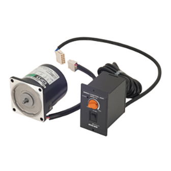
ユニットタイプスピードコントロールモーター
US シリーズ
• 110 V/115 V タイプ
• 220 V/230 V タイプ
取扱説明書
English version follows Japanese version.
お買い上げいただきありがとうございます。
この取扱説明書には、製品の取り扱いかたや安全上の注意事項を示しています。
・取扱説明書をよくお読みになり、製品を安全にお使いください。
・お読みになったあとは、いつでも見られるところに必ず保管してください。
もくじ
1 安全上のご注意 ................................... 2
2 現品到着時の確認 ............................... 4
2.1 現品の確認 .............................................. 4
2.2 品名および組み合わせの確認 .................. 5
3 取り付け .............................................. 6
3.1 取付条件 .................................................. 6
3.2 モーターの取り付け................................... 6
3.3 コントロールユニットの取り付け ................. 8
(コンデンサ外付けタイプの場合) .............. 9
3.5 EMC 指令に適合させる設置・配線方法... 10
4 接 続................................................. 12
5 運 転.................................................13
5.1 モーターの運転・変速・停止..................... 13
5.2 一方向運転で使用する場合 .................... 14
5.3 正逆運転する場合 .................................. 15
5.4 モーターの回転速度を確認する場合 ....... 16
5.5 モーターを遠隔操作する場合 .................. 16
6 特 性.................................................17
7 拘束時のモーター焼損保護について ...18
チェックポイント....................................19
HM-9218-3
Advertisement
Chapters
Table of Contents

Subscribe to Our Youtube Channel
Related Manuals for Oriental motor US Series


Summary of Contents for Oriental motor US Series
-
Page 1: Table Of Contents
HM-9218-3 ユニットタイプスピードコントロールモーター US シリーズ • 110 V/115 V タイプ • 220 V/230 V タイプ 取扱説明書 English version follows Japanese version. お買い上げいただきありがとうございます。 この取扱説明書には、製品の取り扱いかたや安全上の注意事項を示しています。 ・取扱説明書をよくお読みになり、製品を安全にお使いください。 ・お読みになったあとは、いつでも見られるところに必ず保管してください。 もくじ 1 安全上のご注意 ........2 5 運 転..........13 5.1 モーターの運転・変速・停止..... 13 2 現品到着時の確認 ....... 4 5.2 一方向運転で使用する場合 ....14 2.1 現品の確認... -
Page 2: 安全上のご注意
1 安全上のご注意 1 安全上のご注意 ここに示した注意事項は、製品を安全に正しくお使いいただき、お客様や他の人々への危害や損傷を未然 に防止するためのものです。内容をよく理解してから製品をお使いください。 この警告事項に反した取り扱いをすると、死亡または重傷を負う場合がある内容を示 しています。 この注意事項に反した取り扱いをすると、傷害を負うまたは物的損害が発生する場合 がある内容を示しています。 製品を正しくお使いいただくために、お客様に必ず守っていただきたい事項を、本文 中の関連する取り扱い項目に記載しています。 全 般 • 爆発性雰囲気、引火性ガスの雰囲気、腐食性の雰囲気、水のかかる場所、可燃物のそばでは使用しな いでください。火災・感電・けがの原因になります。 • 接地、接続、運転・操作、点検・故障診断の作業は、適切な資格を有する人が行なってください。火災・ 感電・けがの原因になります。 • 通電状態で移動、設置、接続、点検の作業をしないでください。電源を切ってから作業してください。感 電の原因になります。 • モーターの過熱保護装置(サーマルプロテクタ)がはたらいたときは、電源を切ってください。過熱保護装 置が自動復帰したときにモーターが突然起動して、けが・装置破損の原因になります。 設 置 • モーターはクラスⅠ機器のみに使用してください。感電の原因になります。 • モーターは筐体内に設置してください。感電・けがの原因になります。 • 設置するときは、モーター、コントロールユニットに手が触れないようにするか、接地してください。感電の 原因になります。 接 続 • コントロールユニットの電源入力電圧は、定格値を必ず守ってください。火災・感電の原因になります。 • 接続は接続図にもとづき、確実に行なってください。火災・感電の原因になります。 •... - Page 3 1 安全上のご注意 修理・分解・改造 • モーター、コントロールユニットを分解・改造しないでください。感電・けがの原因になります。内部の点検 や修理は、お買い上げになった支店または営業所に連絡してください。 全 般 • モーター、コントロールユニットの仕様値を超えて使用しないでください。感電・けが・装置破損の原因に なります。 • モーターの開口部に指や物を入れないでください。火災・感電・けがの原因になります。 • 運転中および停止後しばらくの間は、モーターに触れないでください。モーターの表面が高温のため、や けどの原因になります。 運 搬 • モーター出力軸、モーターケーブルを持たないでください。けがの原因になります。 設 置 • モーター、コントロールユニットの周囲には、可燃物を置かないでください。火災・やけどの原因になりま す。 • モーター、コントロールユニットの周囲には、通風を妨げる障害物を置かないでください。装置破損の原 因になります。 • モーターは金属板に確実に固定してください。けが・装置破損の原因になります。 • モーターの回転部(出力軸)に、カバーを設けてください。けがの原因になります。 接 続 • 漏電遮断機を設置してください。火災の原因になります。 運 転 • モーターとコントロールユニットは、指定された組み合わせで使用してください。火災の原因になります。 •...
-
Page 4: 現品到着時の確認
2 現品到着時の確認 2 現品到着時の確認 2.1 現品の確認 以下のものがすべて揃っているか確認してください。 不足したり破損している場合は、最寄りの支店・営業所にご連絡ください。 • モーター..............1 台 • コントロールユニット ..........1 台 • コントロールユニット取付用 M3 ねじセット ..1 セット (ねじ、ワッシャ、ナット 各 4 個) • 取扱説明書(本書) ..........1 部 規格・CE マーキング モーターおよびコントロールユニットは下記の規格に従って設計、検査を行ない、認定を取得しています。 認定品名は、モーター品名およびコントロールユニット品名です。 モーター、コントロールユニットは低電圧指令に適合しています。 モーター コントロールユニット UL 1004、UL 2111 UL 508 認定規格... -
Page 5: 品名および組み合わせの確認
2 現品到着時の確認 2.2 品名および組み合わせの確認 この製品はモーターとコントロールユニットをセットでお届けしています。 製品がお手元に届きましたら、モーターとコントロールユニットの組み合わせを確認してください。 ■110 V/115 V タイプ コントロールユニット コンデンサの ∗1 ∗2 ユニット品名 モーター品名 適合ギヤヘッド品名 (別売) 品名 タイプ US206-401U2 USM206-401W2 2GN S、2GN K USP206-1U2 US206-001U2 USM206-001W2 - US315-401U2 USM315-401W2 3GN S、3GN K USP315-1U2 US315-001U2 USM315-001W2 - 内 蔵 US425-401U2 USM425-401W2 4GN S、4GN K、4GN RH、4GN RA... -
Page 6: 取り付け
3 取り付け 3 取り付け 3.1 取付条件 モーター、コントロールユニットは以下の条件のところに取り付けてください。 この範囲外で使用すると製品が破損するおそれがあります。 • 屋内(この製品は機器組み込み用に設計、製造されたものです) • 周囲温度 モーター:-10~+40 °C(凍結しないこと) コントロールユニット:0~+40 °C(凍結しないこと) • 周囲湿度 85%以下(結露しないこと) • 爆発性雰囲気、有害なガス(硫化ガスなど)、および液体のないところ • 直射日光が当たらないところ • 塵埃や鉄粉などの少ないところ • 水(雨や水滴)、油(油滴)、およびその他の液体がかからないところ • 放熱しやすいこと • 連続的な振動や過度の衝撃が加わらないところ • 標高 1000 m 以下 3.2 モーターの取り付け 丸シャフトタイプ 取付板にねじ、モーター寸法に合った穴をあけてください。 ねじ、ナット、座金を使用し、モーターを取付板に固定してください。このとき、モーター取付面と取付... - Page 7 3 取り付け 歯切りシャフトタイプ 取付板にねじ、モーター寸法に合った穴をあけてください。 別売りのギヤヘッド付属のねじを使用し、モーターとギヤヘッドを組み付けてください。組み付けは、 それぞれのインロー部を案内として、シャフト歯切り部をギヤヘッド側板(金属板)やギヤに強く当てな いよう、ギヤヘッドを静かに左右に回しながら行なってください。 ギヤヘッド付属のねじで取付板に固定してください。このとき、モーターフランジ面とギヤヘッドイン ロー端面にすきまがないように取り付けてください。 5GU K、5GU KBH、5GN RA、5GU RA タイプは装置への取付ねじは付属していませんので、 M6(GN タイプ)または M8(GU タイプ)のねじを別途ご用意ください。 オプション(別売)で取付金具を用意しています。 取り付けの詳細については、別売りのギヤヘッドの取扱説明書をご参照ください。 • 重要 ギヤヘッドはモーターと同じ歯切りタイプのものを使用してください。 適合ギヤヘッドは、5ページ「2.2 品名および組み合わせの確認」の表で確認してください。 • モーターインロー部、ギヤヘッドインロー部にはゴミなどを付着させないでください。組み付け が不十分となり、ギヤヘッド内のグリースが漏れることがあります。 • 歯に傷が付くと異音の原因になることがあります。 冷却ファン付モーター 冷却ファン付モーターを装置に取り付ける場合には、モーター後部の冷却用吸込口をふさがないように、 ファンカバーの後ろを 10 mm 以上あけるか、換気穴をあけてください。 冷却ファンは、モーター運転中常時回転するわけではありません。 モーターへの入力電圧に応じて回転します。 −7−...
-
Page 8: コントロールユニットの取り付け
3 取り付け 3.3 コントロールユニットの取り付け コントロールユニットを機器に取り付けるときは、2 通りの方法があります。 取り付けは、以下の方法を参考にしてください。 M4 のねじは付属しておりません。お客様でご用意ください。 ねじの締付トルクは 0.7 N·m 未満としてください。 重要 0.7 N·m を超えるトルクで締め付けると、コントロールユニットが破損する場合があります。 四角い穴をあけて取り付ける方法 図のように取付板に穴をあけてください。 2×Ø4.5 取付板の前面からコントロールユニットを挿入し、ねじとナットを用意して固定してください。 2×M4 取付ねじ、ナット サイズ 数 各 2 個 2×M4 四角い穴をあけずに取り付ける方法 図のように取付板に穴をあけてください。 ±0.2 13.2 ±0.2 Ø23 Ø7 Ø28 4×Ø3.5 2×Ø7.5 −8−... -
Page 9: コンデンサの取り付け(コンデンサ外付けタイプの場合
3 取り付け コントロールユニット本体からフロントパネルを取り外してください(フロントパネルだけを持って手前に 引くと外れます)。 付属の M3 のねじとナット各 4 個を使用し、取付板にコントロールユニット本体を固定してください。 以下のねじとナットを用意して、取付板の前面からフロントパネルをかぶせて固定してください。 4×M3 取付ねじ、ナット 2×M4 サイズ 数 各 2 個 4×M3 2×M4 取付板をコントロールユニットとフロントパネルで挟みつけるため、取付板の厚みは 2 mm 以下 重要 にしてください。 3.4 コンデンサの取り付け(コンデンサ外付けタイプの場合) コンデンサの取り付けには、M4 のねじを使用してください(取付用のねじは付属していません)。 Ø4.3 mm • コンデンサに付いているコンデンサキャップは外さないでください。 重要 • ねじの締付トルクは、取付足の破損防止のため、1 N·m 以下としてください。 • コンデンサは、モーターから... -
Page 10: Emc 指令に適合させる設置・配線方法
3 取り付け 3.5 EMC 指令に適合させる設置・配線方法 はじめに • EMC 指令(89/336/EEC、92/31/EEC) US シリーズは、機器組み込み用の部品として設計・製造されています。EMC 指令では、この製品が組み込 まれたお客様の機械装置での適合が要求されます。 これからご紹介するモーター、コントロールユニットの設置・配線方法は、お客様の機械装置の EMC 指令へ の適合に有効な基本的な設置・配線方法について説明したものです。 最終的な機械装置の EMC 指令への適合性は、モーター、コントロールユニットと一緒に使用される他の制 御システム機器、電気部品の構成、配線、配置状態、危険度などによって変わってきますので、お客様ご自 身で機械装置の EMC 試験を行ない、確認していただく必要があります。 • 適用規格 Emission Tests EN 61000-6-4 Radiated Emission Test EN 55011 Conducted Emission Test EN 55011 Immunity Tests EN 61000-6-2 Radiation Field Immunity Test... - Page 11 3 取り付け • 接地方法 接地した箇所に電位差が生じないよう、コントロールユニット、モーター、AC ラインフィルタを接地するケー ブルは、できるだけ太く、最短距離で接地ポイントに接地してください。接地ポイントには広く、太く、均一な 導電面を使用してください。 コントロールユニットの接地 コントロールユニットのアース用リード線を接地してください。 モーターの接地 モーターを接地するときは、モーターの保護接地端子を使って接地してください。接地端子のないものは、 取付フランジの塗装をはがし、菊座ワッシャを使用して、固定ねじと一緒に接地ケーブルを接地ポイントに 接地してください。 • モーターケーブルの接続 モーターケーブルを延長するときは、オプション(別売)の延長ケーブルを使用してください。 詳細は16ページ「5.5 モーターを遠隔操作する場合」をご覧ください。 • 設置・配線についての注意事項 • モーターやコントロールユニットと、周辺の制御システム機器の接地電位に差が生じないように、接地ポイ ントに直接接地してください。 • リレーや電磁スイッチを一緒に使用するときは、AC ラインフィルタや CR 回路でサージを吸収してくださ い。 • モーター、コントロールユニットの設置・配線例 SPEED CONTROL UNIT USP560-2E POWER HIGH STAND-BY B AC 4.75 m Grounded Panel 静電気についての注意事項...
-
Page 12: 接 続
4 接 続 4 接 続 接続手順 以下の説明は、出荷時の設定のまま使用する場合です。 回転方向は、モーター出力軸側からみて時計方向に回転するように設定してあります。 回転方向を変える場合は、13ページ「5 運 転」を参照してください。 図は 110 V/115 V コンデンサ内蔵タイプです。 緑のアース用リード線を接地してください。このアースはノイズ除去用の機能アースです。 モーター部のコネクタとコントロールユニット部のコネクタを接続してください。このとき、コネクタは「カ チッ」という音がするまで差し込んで、確実に接続してください。 コントロールユニットの「RUN/STAND-BY」スイッチが「STAND-BY」、回転速度設定器のツマミが 「LOW」になっていることを確認してから、電源コードを電源に接続してください。電源を投入するとコ ントロールユニットの POWER LED(緑)が点灯します。 モーターの保護接地端子 を接地してください。 Ø4.1 mm 適用圧着端子:絶縁被覆付き丸型圧着端子 端子ねじサイズ:M4 締付トルク:1.0~1.3 N·m 4.8 mm 適用リード線:AWG18(0.75 mm )以上 ∗ 60 W、90 W タイプには保護接地端子がありません。11ページ「接地方法」でご確認ください。 SPEED OUT AC110 V 60 Hz AC115 V 60 Hz... -
Page 13: 運 転
5 運 転 5 運 転 • このモーターは B 種絶縁モーターです。モーター運転中は、モーターケースの温度が 90 °C を 重要 超えないことを確認してください。90 °C を超える温度でモーターを運転すると、巻線、ボール ベアリングの寿命を短くします。 モーターケースの温度は、モーター表面に温度計を固定して計測できます。また、サーモテー プまたは熱電対を使用しても計測できます。 • 60 W、90 W タイプの場合、低速、軽負荷で運転するとモーターの発熱が少ないため、モー ター後部の冷却ファンは回転しない設定になっています。 • コントロールユニット内部には、外部からのノイズに対するフィルタを内蔵していますが、ノイズ のレベルによっては設定回転速度と異なる回転速度で回るなどの誤動作を招く場合がありま す。機器に取り付け後、実機にて確認してください。誤動作する場合は、ノイズフィルタ、フェラ イトコアなどを取り付けることにより防止することができます。 • コントロールユニットの電源コード端子台のリード線を差し替える場合は、電源を OFF にして から行なってください。 5.1 モーターの運転・変速・停止 POWER LED POWER RUN/STAND-BY HIGH... -
Page 14: 一方向運転で使用する場合
5 運 転 最高速度調整方法 フロントパネルを外して、以下の手順で調整してください。 「RUN/STAND-BY」スイッチを「RUN」側に倒します。 回転速度設定器のツマミを最大まで回します。 最高速度調整用トリマを回し、50 Hz:1400 r/min、60 Hz:1600 r/min になるように調整してください。 左へ回すと速くなり、右へ回すと遅くなります。調整には絶縁されたプラスの精密ドライバを使用してく ださい。 最高速度調整用トリマを使用して調整する場合、使用する電源周波数が変わるときは、再度調 重要 整してください。 5.2 一方向運転で使用する場合 コントロールユニットのコンデンサが内蔵タイプか外付けタイプかにより接続が異なります。 お求めのタイプがどのタイプかは5ページ「2.2 品名および組み合わせの確認」の表でご確認ください。 回転方向は、モーター出力軸側から見て時計方向を CW、反時計方向を CCW としています。 出荷時は時計方向に回転するように設定されているため、電源コード端子台のリード線は N(CW)に接続さ れています。 反時計方向に回転させる場合は、N(CCW)に接続してください。 図は 110 V/115 V タイプです。 出荷時の設定「CW」を「CCW」に変える場合 コンデンサ内蔵タイプ コントロールユニット後部の電源コード端子台のプラスチックカバーを外してください。 電源コード端子に接続されている黒のリード線を、N(CW)から N(CCW)に差し替えてください。 出荷時は電源コード端子が... -
Page 15: 正逆運転する場合
5 運 転 SPEED OUT AC110 V AC110 V 60 Hz N CW AC115 V AC115 V 60 Hz N COM AC220 V 50/60 Hz AC230 V 50/60 Hz N CCW 5.3 正逆運転する場合 電源用スイッチと正逆転切替スイッチを設けて、回転方向を切り替えてください。 モーターの回転方向の切り替えは、モーターが完全に停止してから行なってください。 重要 回転方向が切り替わらなかったり時間がかかったりする場合があります。 コンデンサ内蔵タイプ 電源用スイッチ「SW1」と正逆転切替スイッチ「SW2」を接続してください。 「RUN/STAND-BY」スイッチを「STAND-BY」側に倒し、モーターが完全に停止するのを確認してくだ さい。... -
Page 16: モーターの回転速度を確認する場合
5 運 転 5.4 モーターの回転速度を確認する場合 オプションのデジタル表示型回転計 SDM496(別売)をご使用ください。 電源コード端子の SPEED OUT をデジタル回転計の①、⑪端子に接続してください。 モーターが回転すると、回転速度を表示します。 接続の詳細は、デジタル表示回転計 SDM496 の取扱説明書を参照してください。 SDM496 SPEED デジタル表示型回転計 SDM496 は安全規格認定品ではありません。 重要 US シリーズと組み合わせて使用したときは、US シリーズも安全規格には適合しません。 5.5 モーターを遠隔操作する場合 モーターとコントロールユニット間は標準で 0.75 m ですが、さらに離してお使いになりたい場合は、オプショ ンの延長コードをご使用ください。コードは、最大 4.75 m まで延長できます。 US206、US315、US425、US540 タイプ用 品 名 ケーブル長さ(m) CC01SU05 CC02SU05 CC03SU05 CC04SU05... -
Page 17: 特 性
6 特 性 6 特 性 使用限界線について スピードコントロールモーターは、負荷と回転速度に対応して入力が変わります。負荷が大きいほど、また回 転速度が遅いほど温度上昇は高くなります。 AC スピードコントロールモーターの回転速度-トルク特性のグラフには、図のように「使用限界線」が記入さ れており、この斜線部を連続運転領域と言います。 「使用限界線」はモーターの許容最高温度を超えずに連続で運転できる限界で、モーターの温度から決め られます。 実際の負荷と回転速度で、連続で使えるかどうかは、モーターケースの温度を測定し判断します。モーター ケース温度 90 °C 以下であれば、その条件にて連続使用可能です。 ギヤヘッド使用の場合、ギヤヘッドの許容トルク以下のトルクでお使いください。ギヤヘッドを使用して、この トルクを超えて運転すると寿命が短くなったり、破損することがあります。 50 Hz 60 Hz 60 Hz 50 Hz 1000 1500 1800 r/min −17−... -
Page 18: 拘束時のモーター焼損保護について
7 拘束時のモーター焼損保護について 7 拘束時のモーター焼損保護について モーターの過熱保護装置(サーマルプロテクタ)がはたらいたときは、電源を切ってください。過熱保護装 置が自動復帰したときにモーターが突然起動して、けが・装置破損の原因になります。 このモーターには、モーターに何らかの原因で異常発熱し、焼損に至るのを防止するための機能を備えて います。保護方式には次の 2 通りがあります。 サーマルプロテクタ方式(モーター銘板に「TP」と記載されています) 規定の温度になると、内蔵サーマルプロテクタがはたらいてモーターは停止します。 自動復帰型のため、モーターの温度が下がると自動的に運転を再開します。 点検作業は必ず電源を切ってから行なってください。 開(電源を遮断する)……130±5 °C サーマルプロテクタ動作温度 閉(電源をつなぐ)………82±15 °C インピーダンスプロテクト方式(モーター銘板に「ZP」と記載されています) 異常時に拘束状態になった場合、巻線インピーダンスが大きくなり、モーターへの入力を抑制し、モーター 巻線が焼損に至らないようになっています。 −18−... -
Page 19: 正常に動作しない場合のチェックポイント
8 正常に動作しない場合のチェックポイント 8 正常に動作しない場合のチェックポイント モーターが正常に動作しない場合は、下の表に従って点検してください。 点検の結果、すべて正常であるにもかかわらずモーターおよびコントロールユニットが正しく動作しない場 合は、お客様ご相談センター、または最寄りの支店・営業所にご連絡ください。 現 象 確認内容 モーターが回転しない コントロールユニットに正規の電圧が加えられていますか? モーターとコントロールユニットのコネクタが外れていませんか? 負荷が大きすぎませんか? コントロールユニットの「RUN/STAND-BY」スイッチが「STAND-BY」側に なっていませんか? モーターとコントロールユニットの組み合わせは合っていますか? コントロールユニットの速度設定用ボリュームが LOW になっていませんか? サーマルプロテクタがはたらいていませんか? コンデンサ外付けタイプの場合、コンデンサが「4 接 続」または「5 運 転」の 接続方法どおりに接続されていますか? 逆方向に回転する 接続方法と違う接続をしていませんか? 「4 接 続」または「5 運 転」をもう一度見てください。 ギヤヘッドの減速比によっては、ギヤヘッド出力軸の回転方向が異なります。 ギヤヘッドの取扱説明書を参照してください。 コンデンサ外付けタイプの場合、コンデンサが「4 接 続」または「5 運 転」の 接続方法どおりに接続されていますか? 見る方向が違っていませんか? モーター出力軸側から見て回転方向を時計方向、反時計方向としています。... - Page 20 • この取扱説明書の一部または全部を無断で転載、複製することは、禁止されています。 損傷や紛失などにより、取扱説明書が必要なときは、最寄りの支店または営業所に請求してください。 • 取扱説明書に記載されている情報、回路、機器、および装置の利用に関して産業財産権上の問題が生じても、当社は一切の 責任を負いません。 • 製品の性能、仕様および外観は改良のため予告なく変更することがありますのでご了承ください。 • 取扱説明書には正確な情報を記載するよう努めていますが、万一ご不審な点や誤り、記載もれなどにお気づきの点がありました ら、最寄りのお客様ご相談センターまでご連絡ください。 • は、日本その他の国におけるオリエンタルモーター株式会社の登録商標または商標です。 その他の製品名、会社名は各社の登録商標または商標です。この取扱説明書に記載の他社製品名は推奨を目的としたもので、 それらの製品の性能を保証するものではありません。オリエンタルモーター株式会社は、他社製品の性能につきましては一切の 責任を負いません。 © Copyright ORIENTAL MOTOR CO., LTD. 2008 http://www.orientalmotor.co.jp/ 9:00 18:30 9:00 17:30 TEL 0120-925-410 FAX 0120-925-601 TEL 0120-925-420 FAX 0120-925-602 TEL 0120-925-430 FAX 0120-925-603...
- Page 21 • 110 V/115 V type • 220 V/230 V type OPERATING MANUAL Thank you for purchasing an Oriental Motor product. This Operating Manual describes product handling procedures and safety precautions. · Please read it thoroughly to ensure safe operation. · Always keep the manual where it is readily available.
-
Page 22: Precautions
1 Precautions 1 Precautions The precautions described below are intended to prevent danger or injury to the user and other personnel through safe, correct use of the product. Use the product only after carefully reading and fully understanding these instructions. Handling the product without observing the instructions that accompany a Warning “Warning”... - Page 23 1 Precautions Caution General • Do not use the motor and control unit beyond their specifications, or electric shock, injury or damage to equipment may result. • Keep your fingers and objects out of the openings in the motor, or electric shock, injury or damage to equipment may result.
-
Page 24: Checking The Package Contents
2 Checking the package contents 2.1 Checking the contents Make sure that you have received all of the items listed below. If an accessory is missing or damaged, contact the nearest ORIENTAL MOTOR office. • Motor..............1 unit • Control unit ............1 unit •... -
Page 25: Checking The Product Name And Motor-Control Unit Combination
2 Checking the package contents 2.2 Checking the product name and motor-control unit combination This product comes in a combined set consisting of a motor and a control unit. When the product first arrives, check the nameplates to confirm that you have received the correct motor and control unit combination. 110 V/115 V type Capacitor ∗1... -
Page 26: Installation
3 Installation 3 Installation 3.1 Installation conditions Install the motor and control unit in a location that meets the following conditions. Using the unit in a location that does not satisfy these conditions could damage it. • Indoors (this product is designed and manufactured to be installed within another device) •... - Page 27 3 Installation Pinion shaft motor Drill holes in the mounting plate that match the screws and the motor’s dimensions. Attach the motor and gearhead using the screws supplied with the gearhead (sold separately). Attach by using the pilot section as a guide and rotating the gearhead gently left and right, being careful that the shaft’s gear pinion section does not strike the gearhead side plate (metal plate) or gears strongly.
-
Page 28: Installing The Control Unit
3 Installation 3.3 Installing the control unit There are two methods for mounting the control unit onto a machine. Refer to the mounting methods described below. M4 screws are not provided with the control unit. Users must supply these screws on their own. Use a tightening torque of 0.7 N·m (6.1 lb-in) or less for the screws. -
Page 29: Installing The Capacitor (When Using A Motor With A Capacitor)
3 Installation Remove the front panel from the control unit. (Grasp the front panel alone and pull forward to remove.) Fasten the control unit to the mounting plate using the 4 M3 screws and nuts provided. Fasten the front panel onto the front of the mounting plate using the screws and nuts listed below (not provided). -
Page 30: Installing And Wiring In Compliance With Emc Directive
Installing and wiring in compliance with EMC directive Effective measures must be taken against the EMI that the US series may give to adjacent control-system equipment, as well as the EMS of the US series itself, in order to prevent a serious functional impediment in the machinery. - Page 31 3 Installation • Grounding procedure The cable used to ground the motor must be as thick and short to the grounding point as possible so that no potential difference is generated. Choose a large, thick and uniformly conductive surface for the grounding point.
-
Page 32: Connection
4 Connection 4 Connection Connection steps Below is an explanation of how to use the unit as it was set up at the factory. The motors direction of rotation is set in a clockwise direction viewing the motor from the side with the output shaft. -
Page 33: Operation
5 Operation 5 Operation • This motor is B type insulation motor. Make sure that the motor case temperature does Note not exceed 90 °C (194 °F) during motor operation. Operating the motor above 90 °C (194 °F) will shorten the life of the coil and the ball bearings. Motor case temperature can be measured by fastening a thermometer to the motor’s surface, or with thermo-tape. -
Page 34: Operating The Motor In One Direction
5 Operation How to adjust maximum speed Remove the front panel and adjust the maximum speed according to the following procedure: Set the “RUN/STAND-BY” switch to “RUN”. Turn the speed potentiometer to the maximum level. Turn the maximum-speed adjustment potentiometer until 1400 r/min (50 Hz) or 1600 r/min (60 Hz) is reached. -
Page 35: Switching Between Rotation Directions
5 Operation Replace the plastic cover over the power cord terminal block. Control unit rear panel Power cord terminal block White Black 110 VAC 60 Hz 115 VAC 60 Hz 220 VAC 50/60 Hz 230 VAC 50/60 Hz Capacitor Yellow Green (Ground lead wire) 5.3 Switching between rotation directions Users must provide a power switch and a forward/reverse switch. -
Page 36: Checking The Motor's Speed
The digital speed indicator SDM496 is not certified by the recognized safety standards. Note When the digital speed indicator is used with the US series, which is certified by the recognized safety standards and/or the conformed safety standards, the US series itself is not in conformance with the safety standards. -
Page 37: Characteristics
6 Characteristics 6 Characteristics Safe-operation line Input power to the speed control motor varies with the load and the speed. The greater the load, and the lower the speed, the higher the motor’s temperature will rise. The graph left displays the relationship between the speed and the torque characteristics of the AC speed control motor. -
Page 38: Locked Rotor Burnout Protection Of Motor
7 Locked rotor burnout protection of motor 7 Locked rotor burnout protection of motor Warning Turn off the power in the event the overheat protection device (thermal protector) is triggered. Failure to do so may result in injury or damage to equipment, since the fan will start abruptly when the overheat protection device (thermal protector) is automatically reset. -
Page 39: Troubleshooting
When the motor is not functioning normally, perform an inspection covering the points listed in the table below. If the inspection shows that everything is normal but the motor and control unit still are not functioning normally, contact the nearest ORIENTAL MOTOR office. Problem Things to check... - Page 40 • Unauthorized reproduction or copying of all or part of this manual is prohibited. If a new copy is required to replace an original manual that has been damaged or lost, please contact your nearest Oriental Motor branch or sales office.
- Page 41 HM-9218-3 组合型调速电动机 US 系列 • 110 V/115 V 型 • 220 V/230 V 型 使用说明书 衷心感谢您对本公司产品的惠顾。 本使用说明书就产品的使用方法与安全注意事项进行说明。 请仔细阅读使用说明书,并在使用产品时注意安全。 • 阅读完使用说明书后,务请将其保存在合适的地方,以便随时可以查阅。 • 目 次 1 安全注意事项 ........2 5 运 转..........13 5.1 电动机的运转·调速·停止 ....13 2 产品及品名的确认 ....... 4 5.2 单方向运转时 ......... 14 2.1 验货...
-
Page 42: 安全注意事项
1 安全注意事项 1 安全注意事项 这里提示的注意事项,其目的是为了使您能安全、正确地使用本产品,并防患于未然,以免对您和他 人造成危害和损伤。请您在对其内容充分理解后再使用本产品。 在操作时违反本警告事项所示的内容要求,可能会导致人员死亡或负重伤。 在操作时违反本注意事项所示的内容要求,可能会导致人员负伤或造成物品损坏。 为了使您能正确使用产品,在正文的相关使用项目中记载着请用户务必遵守的事 项。 整 体 • 请勿在爆炸性环境、可燃性气体环境、腐蚀性环境、容易沾水的场所及可燃物附近使用本产品,否 则有可能引起火灾、触电或致伤。 • 安装、接线、运转·操作 、检查·故障诊断等作业请由有适当资格的人实施,否则有可能引起火灾、 触电或致伤。 • 请勿在通电状态下进行移动、安装、接线和检查作业。请切断电源后再进行作业,否则有可能引起 触电。 • 电动机的热保护器(Thermal Protector)动作时,请切断电源,否则热保护器自动回复后,电动机会突 然起动,有可能致伤或造成设备损坏。 安 装 • 电动机只能使用在等级Ⅰ的机器上,否则有可能引起触电。 • 请将电动机安装在框体内,否则有可能引起触电或致伤。 • 安装电动机时,请采取措施使手无法触及电动机和控制器,或者将其接地,否则有可能引起触电。 接 线 • 控制器的电源输入电压请务必控制在额定范围内,否则有可能引起火灾或触电。 • 请按照接线图确实地进行接线,否则有可能引起火灾或触电。 •... - Page 43 1 安全注意事項 整 體 • 使用電動機、控制器時,請勿超過其規格值,否則有可能引起觸電、致傷或造成設備破損。 • 請勿將手或其他物體插入電動機的開口部中,否則有可能引起火災、觸電或致傷。 • 運轉中及停止后短時間內,請勿碰觸電動機,否則有可能因電動機表面的高溫而引起燙傷。 搬 運 • 搬運時請勿手持電動機出力軸、電動機電纜線,否則有可能致傷。 安 裝 • 電動機、控制器周圍請勿堆放可燃物,否則有可能引起火災或燙傷。 • 電動機、控制器周圍請勿堆放妨礙通風的障礙物,否則有可能造成設備破損。 • 請將電動機確實固定在金屬板上,否則有可能致傷或造成設備破損。 • 請在電動機的旋轉部(出力軸)上安裝防護罩,否則有可能致傷。 接 線 • 請安裝漏電遮斷器,否則有可能引起火災。 運 轉 • 請按指定的搭配使用電動機與控制器,否則有可能引起火災。 • 为了在发生设备故障或动作异常时维护设备装置的整体安全,请将紧急停止装置或紧急停止电路配 备在设备的外部。否则有可能致伤。 • 出现异常时,请立即停止运转,切断控制器的电源,否则有可能引起火灾、触电或致伤。 • 要接通電源時,請先將控制器的 RUN/STAND-BY 開關扳到 STAND-BY(待機)一側,並將運轉速度 設定器設定為...
-
Page 44: 产品及品名的确认
2 产品及品名的确认 2 产品及品名的确认 2.1 验货 请确认下列物品是否齐全,若有缺件或破损时,请与欧立恩拓电机商贸(上海)有限公司联系。 • 电动机··········································1 台 • 控制器··········································1 台 • 控制器安装用 M3 螺丝组 ···········1 组 (螺丝、垫圈、螺帽 各 4 个) • 使用说明书(本说明书)···············1 册 规格和 CE 标志 电动机与控制器按下述规格设计、检查,并已取得规格认证。 电动机品名及控制器品名皆为认证品名。电动机单体已取得中国强制产品认证制度(CCC 制度)的认 证。 电动机与控制器符合低电压指令。 电动机 控制器 认证规格 UL 1004、UL 2111 UL 508 CSA C22.2 No.100、CSA C22.2 No.77 CSA C22.2 No.14... - Page 45 2 產品及品名的確認 2.2 品名及搭配的確認 本系列產品為電動機與控制器配套的產品。 收到產品后,請確認電動機與控制器的搭配是否正確。 ■110 V/115 V 型 ∗1 ∗2 組合品名 電動機品名 控制器品名 電容器類型 適用減速機品名(另售) US206-401U2 USM206-401W2 2GN S、2GN K USP206-1U2 US206-001U2 USM206-001W2 - US315-401U2 USM315-401W2 3GN S、3GN K USP315-1U2 US315-001U2 USM315-001W2 - 內藏 US425-401U2 USM425-401W2 4GN S、4GN K、4GN RH、4GN RA USP425-1U2 US425-001U2 USM425-001W2...
-
Page 46: 安 装
3 安 装 3 安 装 3.1 安装条件 电动机与控制器须按下述条件安装,否则产品将有被损坏的危险。 • 室内(本产品是为组装入机器中使用而设计、制造的) • 周围温度 电动机:-10~ 40 ℃(不得冻结) + 控制器:0~ 40 ℃(不得冻结) + • 周围湿度 85%以下(不得结露) • 没有爆炸性环境、有害气体(硫化气体等)及液体 • 无直射阳光照射 • 尘埃、铁粉等较少 • 不会沾染水(雨或水滴) 、油(油滴)及其它液体 • 易散热 • 没有连续性振动或过度冲击 • 海拔 1000 m以下 3.2 电动机安装... - Page 47 3 安 裝 齒輪軸型 按照螺絲及電動機的尺寸在安裝板上鑽孔。 請使用另售的減速機所附屬的螺絲來組裝電動機和減速機。安裝時請將電動機與減速機沿著雙方 的凸緣部輕輕左右旋轉嵌入。此時請小心勿使轉軸的齒輪部碰撞減速機的側板(金屬板)及齒輪。 請使用減速機附屬的螺絲固定安裝板,此時請注意勿使電動機的安裝面與減速機凸緣面之間留有 縫隙。 5GU K、5GU KBH、5GN RA、5GU RA 型未附屬安裝到裝置上用的螺絲,所以請另外準 備 M6(GN 型)或 M8(GU 型)螺絲。 本公司的選購配件中備有安裝金屬片(另售)。 詳細請參照另售的減速機的使用說明書。 • 請使用與電動機相同的齒輪型減速機。適用減速機型請參照 P.5「2.2 品名及搭配的確認」 重要 之表。 • 請勿使電動機及減速機的凸緣粘附灰塵,否則有可能因安裝不密合而引起減速機內的潤滑 油外漏。 • 若碰傷齒輪會產生雜音。 附散熱風扇型 安裝附散熱風扇型的電動機時,為了避免堵塞電動機后部的散熱孔,請在風扇外框后部空出 10 mm 以上或開換氣孔。 電動機運轉過程中散熱風扇並非一直在旋轉,而是根據輸入電動機的電壓大小在需要時旋轉。 -7-...
- Page 48 3 安 裝 3.3 控制器的安裝方法 控制器的安裝方法有兩種,請參照下述方法進行安裝。 M4 螺絲請自備。 重要 螺絲的安裝力矩請控制在 0.7 N·m 以下,否則有可能損壞控制器。 鑽四角孔的安裝方法 請按左圖所示在安裝板上鑽孔。 請將控制器從安裝板前面插入並用螺絲和螺帽進行固定。 安裝螺絲、螺帽 規格 數量 各 2 個 不鑽四角孔的安裝方法 按左圖所示在安裝板上鑽孔。 -8-...
- Page 49 3 安 裝 將控製面板卸下。(抓住控製面板往前一拉即可卸下) 使用附屬的 4 個 M3 螺絲及螺帽,將控制器固定在安裝板上。 準備以下的螺絲和螺帽,將控製面板蓋在安裝板的正面並固定。 安裝螺絲、螺帽 規格 數量 各 2 個 因安裝板是夾在控制器與控製面板之間,故安裝板的厚度請設定在 2 mm 以下。 重要 3.4 電容器安裝方法(外接電容器型) 請使用 M4 螺絲安裝電容器。(螺絲不附屬) • 重要 請勿拆下電容器套。 • 為防止損壞安裝腳,請將螺絲的安裝力矩控制在 1 N·m。 • 請將電容器安裝在距電動機 10 cm 以上的地方。因為電動機產生的熱量會影響電容器的使 用壽命。電容器用導線(黃色)長度約為 30 cm。 -9-...
- Page 50 3 安 裝 3.5 適合 EMC 指令的安裝‧配線方法 前言 • EMC 指令(89 / 336 / EEC、92 / 31 / EEC) US 系列是作為機器組裝用的產品而設計、製造的。EMC 指令,要求組裝了該產品的用戶的機械設備 滿足指令。 下面介紹的電動機和控制器的安裝和配線方法是能使用戶的機械設備滿足 EMC 指令的有效的基本方 法。 與 US 系列一起使用的其他控制系統、電氣零件的構成、配線、配置狀態和危險度等都會影響到最 終的機械設備是否能滿足 EMC 指令的要求,所以必需請用戶自己進行機械裝置的 EMC 試驗來加以 確認。 • 適用規格 Emission Tests EN 61000-6-4 Radiated Emission Test EN 55011...
- Page 51 3 安 装 • 接地方法 为了防止接地处出现电位差,控制器、电动机及 AC 线路滤波器接地所用的电缆线请尽可能采用粗导 线,并以最短距离在接地点接地。在接地点,请使用大面积、粗导线、均匀的导电面。 控制器的接地 请将控制器的接地用导线接地。 电动机的接地 电动机接地时、请使用电动机的保护接地端子进行接地。给没有接地端子的产品进行接地时、请刮去 安装法兰盘上的涂漆层、并使用菊形垫圈垫圈、配合固定用螺丝、将接地电缆线在接地点上接地。 • 电动机电缆线的连接 要延长电动机电缆线时,请使用选购配件中的延长导线(另售) 。详细请参照 P.16 的「5.5 远距离操 作电动机时」 。 • 安装·配线的注意事项 • 为了防止电动机、控制器与周围的控制系统机器的地线之间出现电位差,请直接在接地点上接地。 • 与继电器、电磁开关一起使用时,请采用 AC 线路滤波器或 CR 电路来吸收突波。 • 电动机、控制器的接地和配线范例 有关静电的注意事项 静电有可能使控制器出现错误动作或破损。对处于接通电源状态下的控制器,使用时要十分谨慎小 心。 重要 请不要靠近或碰触处于电源接通状态下的控制器。 -11-...
-
Page 52: 接 线
4 接 线 4 接 线 接线顺序 以下说明以按出厂时的设定来使用为前提。 运转方向设定:从电动机出力轴侧看为顺时针方向。 要改变电动机运转方向时,请参照 P.13「5. 运 转」 。 下图为 110 V/115 V 内藏电容器型。 请将绿色接地导线接地。此地线为具有去除杂音机能的地线。 请连接电动机与控制器的连接器部分。将连接器入直至连接器发出「喀喳」声为止,确实连接。 确认控制器的「RUN/STAND-BY」开关设定在「STAND-BY」 、运转速度设定器的旋转钮设定在 「LOW」位置后再接通电源。通电后控制器的 POWER LED(绿色)会亮灯。 请使用电动机的保护接地端子进行接地。 适用压接端子:绝缘被覆圆型压接端子 端子螺丝规格:M4 紧固转矩:1.0~1.3 N·m 适用导线:AWG18(0.75 mm )以上 ∗ 60 W 和 90 W 型号没有保护接地端子。请参照 P.11「接地方法」 。 重要... - Page 53 5 運 轉 5 運 轉 重要 • 此電動機為 B 種絕緣電動機。 請注意當電動機呈運轉狀態時,其外殼溫度不可超過 90 ℃。 電動機若在超過 90 ℃的條件下運轉,將會使線圈及滾珠軸承的使用壽命縮短。 電動機外殼溫度可使用在電動機表面固定溫度計的方法來測定,亦可使用感溫紙或熱電耦 來測量。 60 W、90 W 型的電動機在低速、輕負載運轉時,電動機發熱現象並不顯著,因此電動機 • 后部的散熱風扇設定為關閉。 • 控制器內部裝有消除外部雜訊的過濾器。因雜訊程度的大小,有時會發生電動機不按設定 轉速運轉的誤轉現象。安裝完成后請試轉確認。可採取安裝雜訊過濾器或鐵氧體磁心方法 防止出現誤轉。 • 變更控制器電源端子台上的導線時,請先關閉電源。 5.1 電動機的運轉·調速·停止 運轉 將控制器的「RUN/STAND-BY」開關扳到「RUN」(運轉)一側。 這樣,就可以運轉速度設定器設定的速度開始運轉。 停止 將控制器的「RUN/STAND-BY」開關扳到「STAND-BY」(待機)一側,電動機即停止。 變速 將運轉速度設定器的旋鈕朝順時針方向旋轉(HIGH 側),電動機的速度即加快;朝逆時針方向旋轉 (LOW 側),則電動機的速度即減慢。...
- Page 54 5 運 轉 最高速度調整方法 請拆下前面板,按以下步驟調整。 將「RUN/STAND-BY」開關到「RUN」(運轉)一側。 將運轉速度設定器的旋鈕轉到最大。 旋轉最高速度微調器,調整到 50 Hz:1400 r/min、60Hz:1600 r/min。朝左旋轉運轉加快,朝右 旋轉運轉減慢。請使用絕緣的精密○ + 螺絲刀進行調整。 重要 使用最高速度微調器進行調整時,在所使用的電源的頻率變化后,請再次進行調整。 5.2 單方向運轉時 因控制器上的電容器類型不同(內藏型與外接型),電動機的連接方法亦有不同。 首先請參照 P.5「2.2 品名及搭配的確認」中的表格確認您所購買的產品的電容器為哪一種類型。 運轉方向的判斷方法為:從電動機出力軸側看,順時針方向為 CW,逆時針方向為 CCW。 因電動機出廠時運轉方向設定為順時針方向,所以電源端子台的導線呈與 N(CW)連接狀態。 要使電動機按逆時針方向運轉,請將導線與 N(CCW)連接。 下圖為 110 V/115 V 型。 將出廠時的「CW」設定改為「CCW」時 內藏電容器型 拆下控制器后部的電源端子台的塑膠蓋。 將接在電源端子台上的黑色導線由 N(CW)改接到 N(CCW)。出廠時電源端子台上的導線連接在 L 與...
- Page 55 5 運 轉 5.3 正逆運轉時 請安裝電源開關及正逆轉切換開關來控制運轉方向。 改變電動機運轉方向的操作一定要在電動機完全停止后進行,否則會出現無法改變電動機運 重要 轉方向或所需時間較長的情形。 內藏電容器型 連接電源開關「SW1」與正逆轉切換開關「SW2」 。 將「RUN/STAND-BY」開關切換到「STAND-BY」側,並確認電動機是否完全停止。 電動機停止后,關掉電源開關「SW1」 ,切換「SW2」 。 將電源開關「SW1」切換到「ON」 。 外接電容器型 拆下連接在電源端子台 N(COM) ,N(CW)上的黑色導線。 連接電源開關「SW1」和正逆轉開關「SW2」 。 將「RUN/STAND-BY」開關切換到「STAND-BY」側,並確認電動機是否完全停止。 電動機停止后,關掉電源「SW1」 ,切換「SW2」 。 將電源開關「SW1」切換到 ON 側。 開關的接點容量 使用容量須在 AC250 V、5 A 以上。 -15-...
- Page 56 5 運 轉 5.4 須確認運轉速度時 請使用數位顯示型轉數計 SDM496(另售)。 請將電源端子台上的 SPEED OUT 與數碣顯示轉數計的①、⑪端子連接。 電動機運轉后運轉速度則會自動顯示。 詳細接線說明請參照數碣顯示轉數計 SDM496 的產品說明。 數碣顯示轉數計 SDM496 並非安全規格認證品。 重要 與 US 系列產品組合使用后,US 系列產品也會不符合安全規格。 5.5 遠距離操作電動機時 電動機與控制器之間的標準距離為 0.75 m ,超過此距離使用時,請使用另售選購配件中的延長電纜 線,其最長可延至 4.75 m。 US206、US315、US425、US540 型用 品名 電纜線長度(m) CC01SU05 CC02SU05 CC03SU05 CC04SU05 US560、US590 型用...
-
Page 57: 特 性
6 特 性 6 特 性 使用界限線 調速電動機的輸入會隨著負載與運轉速度的變化而改變。負載越大,或電動機的轉速越慢,則電動機 的溫度越高。 AC 調速電動機的運轉速度-轉矩特性曲線圖中如左圖所示標有「使用界限線」 ,此斜線部分叫做電動 機的連續運轉領域。 「使用界限線」是指電動機在不超過最高容許溫度的前提下能夠連續運轉的界限,由電動機的溫度決 定。 電動機是否能在實際負載和運轉速度下連續運轉,需要通過測定電動機外殼的溫度來判斷。若電動機 外殼的溫度在 90 ℃以下,則電動機能在設定條件下連續運轉。 使用減速機時,請將轉矩控制在減速機的容許轉矩以下,否則有可能縮短使用壽命或造成破損。 -17-... - Page 58 7 熱保護功能 7 熱保護功能 電動機的熱保護器(Thermal Protector)動作時,請切斷電源,否則熱保護器自動恢復后,電動機會 突然起動,有可能致傷或造成設備破損。 本電動機具備能防止電動機因某種原因異常發熱而導致燒損的保護功能。保護方式有以下兩種。 熱保護方式(銘板上記載為「TP」) 本電動機的線圈部內置了自動復位型熱保護器。 當電動機的內部溫度達到規定值以上時,熱保護器將起作用,電動機將停止。 檢點作業等須在切斷電源后實行。 熱保護器的動作溫度 開(斷電)....130±5 ℃ 關(通電)....82±15 ℃ 阻抗保護方式(銘板上記載為「ZP」) 當電動機發生異常呈拘束狀態時,此保護器能增大線圈的阻抗值,抑制電流輸入電動機以避免電動機 線圈的燒損。 -18-...
-
Page 59: 运转异常时的检查事项
8 运转异常时的检查事项 8 运转异常时的检查事项 电动机动作异常时,请按下表进行检查。 若检查结果为全部符合要求但电动机或控制器仍无法正常动作时,请与欧立恩拓电机商贸(上海)有限 公司联系。 现象 确认内容 电动机不转 控制器的电压是否符合规格? 电动机与控制器的连接器部分是否脱落? 负载是否过大? 控制器的「RUN/STAND-BY」开关是否在「STAND-BY」侧? 电动机与控制器的搭配是否正确? 控制器的运转速度设定器的旋钮是否设在 LOW 侧? 热保护器是否动作? 若电容器为外接型,是否按照「4. 接 线」或「5. 运 转」中指示的方法 正确连接? 电动机逆转 是否没有按照说明书中规定的接线方法接线? 请再次参照「4. 接 线」或「5. 运 转」 。 减速机因减速比不同,出力轴运转方向亦有所不同,请参照减速机的使用 说明书。 若电容器为外接型,是否按照「4. 接 线」或「5. 运 转」中指示的方法 正确连接? 目测方法是否有错? 电动机运转方向是以从电动机出力轴侧目测的运转方向来判断是顺时针方... - Page 60 • 本使用说明书的一部分或全部内容禁止擅自转载、拷贝。 因损坏或遗失而需要新置使用说明书时,请向欧立恩拓电机商贸(上海)有限公司索取。 • 使用说明书中所记载的情报、电路、机器及装置,若在使用方面出现与之相关的工业产权上的问题,本公司不承担任何责 任。 • 产品的性能、规格及外观可能因改良而有所变化,请予了解。 • 我们力求使使用说明书的内容尽可能正确,如果您发现有什么问题或错误、遗漏之处,请与欧立恩拓电机商贸(上海)有限 公司联系。 • 是东方马达株式会社在日本及其它国家的注册商标或商标。 其他产品名、公司名是各公司的注册商标或商标。本说明书中提及了其他公司的产品名称,目的仅在于向您推荐,并不保 证这些产品的性能。东方马达株式会社对其他公司的产品的性能或使用不承担任何责任。 © Copyright ORIENTAL MOTOR CO., LTD. 2008 Tel:(021)6237-5440 Fax:(021)6237-5433 Tel:+852-2427-9800 Fax:+852-2427-9311 KOREA Tel:66-2-254-6113 Fax:66-2-254-6114 Tel:(032)822-2042~3 Fax:(032)819-8745 Headquarters Tokyo, Japan Tel:(6745)7344 Fax:(6745)9405 Tel:(03)3835-0684 Fax:(03)3835-1890 Tel:(03)22875778 Fax:(03)22875528...
Need help?
Do you have a question about the US Series and is the answer not in the manual?
Questions and answers