Table of Contents
Advertisement
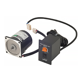
Speed Control Motor and Control Unit Package
US Series
• 110 V/115 V type
• 220 V/230 V type
OPERATING MANUAL
Thank you for purchasing an Oriental Motor product.
This Operating Manual describes product handling procedures and safety precautions.
• Please read it thoroughly to ensure safe operation.
• Always keep the manual where it is readily available.
Table of Contents
1 Precautions .......................................................... 2
2 Checking the package contents .................. 4
2.1 Checking the contents ..............................................4
3 Installation ........................................................... 6
3.1 Installation conditions ...............................................6
3.2 Mounting the motor ..................................................6
3.3 Installing the control unit .........................................7
(when using a motor with a capacitor) ...............8
EMC directive ................................................................8
4 Connection ........................................................10
5 Operation ...........................................................11
5.1 Starting, Changing speeds, Stopping ............... 11
5.2 Operating the motor in one direction .............. 12
5.3 Switching between rotation directions ........... 12
5.4 Extension cables ....................................................... 13
6 Characteristics ..................................................14
motor ...................................................................14
8 Troubleshooting ..............................................15
HM-9218-6
Advertisement
Table of Contents

Related Manuals for Oriental motor US Series


Summary of Contents for Oriental motor US Series
-
Page 1: Table Of Contents
HM-9218-6 Speed Control Motor and Control Unit Package US Series • 110 V/115 V type • 220 V/230 V type OPERATING MANUAL Thank you for purchasing an Oriental Motor product. This Operating Manual describes product handling procedures and safety precautions. -
Page 2: Precautions
Precautions 1 Precautions The precautions described below are intended to prevent danger or injury to the user and other personnel through safe, correct use of the product. Use the product only after carefully reading and fully understanding these instructions. WARNING Handling the product without observing the instructions that accompany a “WARNING”... - Page 3 Precautions CAUTION General • Do not use the motor and control unit beyond their specifications, or electric shock, injury or damage to equipment may result. • Keep your fingers and objects out of the openings in the motor, or electric shock, injury or damage to equipment may result.
-
Page 4: Checking The Package Contents
Checking the package contents 2 Checking the package contents 2.1 Checking the contents Make sure that you have received all of the items listed below. If an accessory is missing or damaged, contact the nearest ORIENTAL MOTOR office. • Motor ..................1 unit •... -
Page 5: Checking The Product Name And Motor-Control Unit Combination
Checking the package contents 2.2 Checking the product name and motor-control unit combination This product comes in a combined set consisting of a motor and a control unit. When the product first arrives, check the nameplates to confirm that you have received the correct motor and control unit combination. •... -
Page 6: Installation
Installation 3 Installation 3.1 Installation conditions Install the motor and control unit in a location that meets the following conditions. Using the unit in a location that does not satisfy these conditions could damage it. • Indoors (this product is designed and manufactured to be installed within another device) •... -
Page 7: Installing The Control Unit
Installation „ Motor with cooling fan Equipment In ow When mounting a motor with a cooling fan onto a device, open a ventilation hole or leave 10 mm (0.4 in.) or more behind the fan cover so that the cooling inlet on the back of the motor cover is not blocked. The cooling fan does not always operate while the motor is running. -
Page 8: Installing The Capacitor (When Using A Motor With A Capacitor)
EMS of the US series itself, in order to prevent a serious functional impediment in the machinery. The use of the following installation and wiring methods will enable the US series to be compliant with the EMC directive (the aforementioned compliance standards). - Page 9 Installation • Motor cable connection When the motor cable is extended, use the optional extension cables (sold separately). Refer to the table of "5.4 Extension cables" on page 13. • Notes about installation and wiring • Connect the motor and other peripheral control equipment directly to the grounding point so as to prevent a potential difference from developing between grounds.
-
Page 10: Connection
Connection 4 Connection „ Connection steps Below is an explanation of how to use the unit as it was set up at the factory. The motors direction of rotation is set in a clockwise direction viewing the motor from the side with the output shaft. When changing the motors direction, refer to section "5 Operation"... -
Page 11: Operation
Operation 5 Operation • Make sure that the motor case temperature does not exceed 90 °C (194 °F) during motor operation. Note Operating the motor above 90 °C (194 °F) will shorten the life of the coil and the ball bearings. Motor case temperature can be measured by fastening a thermometer to the motor’s surface, or with thermo-tape. -
Page 12: Operating The Motor In One Direction
Operation 5.2 Operating the motor in one direction Connections differ depending on the type of capacitor, internal or external. To identify the capacitor type, refer to the table in section "2.2 Checking the product name and motor-control unit combination" on page 5. The motor rotates in a clockwise (CW) and counterclockwise (CCW) direction (viewing the motor from the side with the output shaft). -
Page 13: Extension Cables
Operation „ Motor with external capacitor Disconnect the black lead wire connected to N (COM) and N (CW) of the power cord terminal block. Connect a power switch “SW1” and a forward/ AC power supply N (CW) reverse switch “SW2”. N (COM)... -
Page 14: Characteristics
Characteristics 6 Characteristics „ Safe-operation line Input power to the speed control motor varies with the load and the speed. The greater the load, and the lower the speed, the higher the motor’s temperature will rise. The graph left displays the relationship between the speed and the torque characteristics of the AC speed control motor. The line is referred to as the safe-operation line and the shaded area is called the continuous operation area. -
Page 15: Troubleshooting
Troubleshooting 8 Troubleshooting When the motor is not functioning normally, perform an inspection covering the points listed in the table below. If the inspection shows that everything is normal but the motor and control unit still are not functioning normally, contact the nearest ORIENTAL MOTOR office. - Page 16 • Please contact your nearest Oriental Motor o ce for further information. Singapore Korea Technical Support Tel:(800)468-3982 Tel:1800-8420280 Tel:080-777-2042 8:30 to 5:00 , P.S.T. (M-F) A.M. P.M. www.orientalmotor.com.sg www.inaom.co.kr 7:30 to 5:00 , C.S.T. (M-F) A.M. P.M. www.orientalmotor.com Tel:1800-806161 Hong Kong Branch Tel:+55-11-3266-6018 www.orientalmotor.com.my...
Need help?
Do you have a question about the US Series and is the answer not in the manual?
Questions and answers