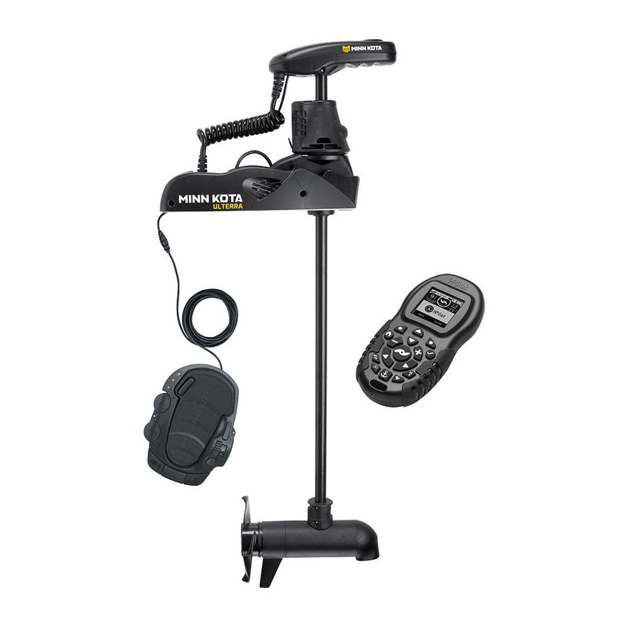
MINN KOTA ULTERRA Owner's Manual
Bow-mount trolling motor
Hide thumbs
Also See for ULTERRA:
- User manual ,
- Installation instructions manual (84 pages) ,
- Owner's manual (82 pages)
Table of Contents
Advertisement
Advertisement
Table of Contents
Troubleshooting

Related Manuals for MINN KOTA ULTERRA


Summary of Contents for MINN KOTA ULTERRA
- Page 1 ULTERRA™ BOW-MOUNT TROLLING MOTOR Owner's Manual...
- Page 2 Thank you for choosing Minn Kota. We believe that you should spend more time fishing and less time positioning your boat. That’s why we build the smartest, toughest, most intuitive trolling motors on the water. Every aspect of a Minn Kota trolling motor is thought out and rethought until it’s good enough to bear our name.
-
Page 3: Table Of Contents
Changing the Prop Orientation ..................42 Adjusting the Lift Belt ....................45 Greasing the Latch Pin and Power Tilt Motor Shaft ............45 Stowing from the Ulterra Motor ................... 46 Trim/Stow Reset Procedure ..................47 Manually Stowing the Ulterra ..................48 ADVANCED GPS NAVIGATION WIRELESS REMOTE ................ -
Page 4: Safety Considerations
WARNING You are responsible for the safe and prudent operation of your vessel. We have designed your Minn Kota product to be an accurate and reliable tool that will enhance boat operation and improve your ability to catch fish. This product does not relieve you from the responsibility for safe operation of your boat. -
Page 5: Warranty
Minn Kota Limited Two-Year Warranty on the Entire Product JOME warrants to the original retail purchaser only that the purchaser’s new Minn Kota freshwater trolling motor will be materially free from defects in materials and workmanship appearing within two (2) years after the date of purchase. JOME will (at its option) either repair or replace, free of charge, any parts found by JOME to be defective during the term of this warranty. -
Page 6: Know Your Boat
KNOW YOUR bOAT Starboard Starboard Port Port Inboard Inboard Outboard Outboard Keel Keel Port Port Starboard Starboard Gunwale Gunwale Transom Transom Stern Stern Gunwale Gunwale Stern Stern Hull Hull 6 | minnkota.johnsonoutdoors.com ©2023 Johnson Outdoors Marine Electronics, Inc. -
Page 7: Features
Advanced GPS Navigation Navigation Power Button Power Button Status Status Indicator Indicator System Ready Indicator System Ready Indicator ULTERRA Indicator Panel Indicator Panel Power Trim Power Trim Motor Mount Motor Mount Auto Stow/Deploy Auto Stow/Deploy Lifetime Warranty Lifetime Warranty Flexible Composite Shaft... -
Page 8: Installation
INSTALLING THE ULTERRA Your new Ulterra comes with everything you’ll need to directly install it to the boat. This motor can be directly mounted to the boat or it may be coupled with a Minn Kota quick release bracket for ease of mounting and removal. For installation with a quick release bracket, refer to the installation instructions provided with the bracket. -
Page 9: Installing The Ulterra
Screw Screw Screw Screw Screw Screw NOTICE: This motor weighs approximately 70 lbs. Minn Kota recommends having a second person help with Stowed Stowed Deployed Deployed the installation. Remove the Right Sideplate to access the Mounting Slots. Remove the Left Sideplate to access the Mounting Holes. - Page 10 Deck of Boat NOTICE: The Emergency Strap (Item #9) is used for manually stowing the Ulterra. The Emergency Strap is not secured during installation. Store it on your boat in the event that you would need to manually stow the motor.
- Page 11 INSTALLING THE ULTERRA ITEM(S) NEEDED #8 x 6 WARNING NOTICE: Failure to allow 1-1/2" of clearance for the Shaft when mounting may cause failures when the motor stows and deploys. Follow recommended mounting considerations Illustrations are for reference only. Do not deploy the motor to avoid obstructions when operating the motor.
- Page 12 NOTICE: The Short Bolts (Item #4) are only used when installing the Ulterra to a quick release bracket. If installing the Ulterra to a quick release bracket, please refer to the instructions that came with the bracket for more information. Quick release bracket installation instructions can also be viewed online at minnkota.johnsonoutdoors.com.
- Page 13 NOTICE: The Short Bolts (Item #4) are only used Washer Washer when installing the Ulterra to a quick release bracket. If installing the Ulterra to a quick release Mounting Mounting Holes Holes bracket, please refer to the instructions that came...
- Page 14 INSTALLING THE ULTERRA At this point in the installation process, the Motor should be secured to the deck of the boat and can now be reassembled. The Extension Damper can be slid back in place on the Damper Pins. This should...
-
Page 15: Identifying Trolling Motor Features And Their Associated Cables
Feature & Cable Identification The Ulterra is pre-installed with Advanced GPS Navigation - including the ability to connect via Ethernet to a Humminbird unit. It is also installed with sonar, either Dual Spectrum CHIRP or Built-in MEGA Down Imaging. Dual Spectrum CHIRP and Built-in MEGA Down Imaging will be installed in combination with Advanced GPS Navigation. -
Page 16: Feature And Cable Management
FEATURE & CABLE MANAGEMENT Feature & Cable Management DUAL SPECTRUM CHIRP Your trolling motor may be pre-installed with a transducer system Dual Spectrum CHIRP featuring Humminbird’s Dual Spectrum CHIRP. CHIRP stands for “Compressed High Intensity Radar Pulse.” Dual Spectrum CHIRP is a 2D sonar transducer with a temperature sensor that is integrated into the lower unit of the trolling motor. - Page 17 DUAL SPECTRUM CHIRP The integrated design of the Dual Spectrum CHIRP transducer protects it in the lower unit of the trolling motor from underwater hazards and prevents tangles and damage to the transducer cables. In certain situations, air bubbles may adhere to the surface of the Dual Spectrum CHIRP transducer and affect the performance.
- Page 18 If using cable ties, do not over-tighten. Any excess cable should be bundled in a loose loop of no less than 4” in diameter. The connection cable should be routed to the fish finder following Minn Kota recommendations on routing the cables to optimize mobility and maximize functionality.
- Page 19 DUAL SPECTRUM CHIRP If installing directly to a Solix or Apex, the connection Fourteen Pin Fourteen Pin will be flat on the back of the fish finder display. Connector Connector Align the pins on the Accessory Cable with the Dual Spectrum CHIRP Dual Spectrum CHIRP Solix or Apex Solix or Apex...
- Page 20 DUAL SPECTRUM CHIRP ITEM(S) NEEDED #22 x 1 If installing directly to a Helix Adapter Cable, align Fourteen Pin Fourteen Pin Receptacle Receptacle the pins on the accessory cable or extension cable Connector Connector with the receptacle on the Helix Adapter Cable (Item #22).
-
Page 21: Built-In Mega Down Imaging
BUILT-IN MEGA DOWN IMAGING BUILT-IN MEGA DOWN IMAGING Built-in MEGA Down Imaging delivers nearly 3X the output of standard Side Imaging®, and takes fishfinding into the megahertz frequency for the very first time. It uses a razor-thin, high-frequency beam to create picture-like images of structure, vegetation and fish. With Humminbird MEGA imaging sonar built right into the trolling motor, you now have a crystal clear view of what’s directly beneath the boat, without having to manage all of the cables that come with external transducers. - Page 22 BUILT-IN MEGA DOWN IMAGING CAUTION Failure to follow the recommended wire routing for installed features, if equipped, may cause damage to the product and void your product warranty. Route cables away from pinch points or other areas that may cause them to bend in sharp angles. Routing the cables in any way other than directed may cause damage to the cables by being pinched or severed.
- Page 23 BUILT-IN MEGA DOWN IMAGING If installing directly to a Solix or Apex, the connection Fourteen Pin Fourteen Pin will be flat on the back of the fish finder display. Connector Connector Align the pins on the Accessory Cable with the Built-in MEGA Down Built-in MEGA Down Solix or Apex...
- Page 24 BUILT-IN MEGA DOWN IMAGING ITEM(S) NEEDED #22 x 1 If installing directly to a Helix Adapter Cable, align 4h Fourteen Pin Fourteen Pin Receptacle Receptacle the pins on the accessory cable or extension cable Connector Connector with the receptacle on the Helix Adapter Cable (Item #22).
-
Page 25: Advanced Gps Navigation
ADvANCED GPS NAvIGATION Your Minn Kota trolling motor and Humminbird fish finder communicate with each other to change the way you fish. Advanced GPS Navigation offers a large array of features including controlling speed, steering, Spot-Lock, and the ability to record and retrace paths on the water, all at your fingertips. - Page 26 Leads Leads Foot Pedal Foot Pedal NOTICE: Ulterra trolling motors with Advanced GPS Power Connector Power Connector Navigation are also equipped with Sonar. Sonar is pre-installed from the factory and may be either Dual Spectrum CHIRP or Built-in MEGA Down Imaging. A Sonar Cable will be present below the Control Head and run through the center of the Coil Cord.
- Page 27 ADvANCED GPS NAvIGATION ITEM(S) NEEDED #15 x 1 Identify the keyed Receptacle on the Ethernet Eight Pin Eight Pin Control Head Control Head Cable (Item #15). It will be keyed to fit with the Eight Connector Connector Pin Advanced GPS Ethernet Connector below the Ethernet Cable Ethernet Cable Control Head.
- Page 28 ADvANCED GPS NAvIGATION To install the Ethernet Cable, align the pins on Eight Pin Eight Pin the Advanced GPS Ethernet Connector with the Receptacle Receptacle Connector Connector Receptacle on the Ethernet Cable. Notice the keyed connectors. Tighten the Collar from the Ethernet Cable to secure the connection.
- Page 29 Cable Cable Cable to secure the connection. Helix Adapter Cable Helix Adapter Cable NOTICE: Minn Kota provides one Helix Adapter Cable (AS EC QDE - Ethernet Adapter Cable - 720074-1) with every trolling motor equipped with Advanced GPS Navigation. Ethernet...
-
Page 30: Securing Accessory Cables
SECURING ACCESSORY CABLES Securing Accessory Cables Before securing the cables, please review the "Identifying Trolling NOTICE: If only one cable is present below the Control Motor Features and Their Associated Cables" section of this Head, this installation is not applicable. document. - Page 31 SECURING ACCESSORY CABLES Place the motor in the stowed position. Confirm all Accessory Cables are connected to an output device as desired. Ensure the Accessory Cables are parallel to each Control Head Control Head other inside the Coil Cord. Run the Accessory Cables Pre-installed Pre-installed from the Control Head to the Mount, keeping them...
- Page 32 SECURING ACCESSORY CABLES Follow the Accessory Cables from the Control Head to the Mount and place additional Cable Ties every Cable Tie Cable Tie 4 inches. The number of Cable Ties needed will vary depending on the length of the trolling motor Shaft. Approximately Approximately 4 inches...
-
Page 33: Installing The Prop
INSTALLING THE PROP Installing the Prop CAUTION Drive Drive Shipping Shipping Prop Prop Washer Washer Disconnect the motor from the battery before (discard) (discard) beginning any prop work or maintenance. While holding the Shipping Spacer with a pliers or vise grip, remove the Prop Nut, Red Shipping Washer, Prop Washer and Spacer, being careful Prop Prop... -
Page 34: Battery & Wiring Installation
CAUTION These guidelines apply to general rigging to support your Minn Kota motor. Powering multiple motors or additional electrical devices from the same power circuit may impact the recommended conductor gauge and circuit breaker size. If you are using wire longer than that provided with your unit, follow the conductor gauge and circuit breaker sizing table below. -
Page 35: Selecting The Correct Batteries
(flooded, AGM or GEL). Lithium-ion batteries maintain higher voltages for longer periods of time than lead acid. Therefore, running a Minn Kota trolling motor at speeds higher than 85% for a prolonged period could cause permanent damage to the motor. -
Page 36: Connecting The Batteries In Series
CONNECTING THE BATTERIES IN SERIES The negative (-) connection must be connected to the negative terminal of the same battery that the trolling motor negative lead connects to. In the diagrams below this battery is labeled “Low Side” Battery. Connecting to any other trolling motor battery will input positive voltage into the “ground”... - Page 37 CONNECTING THE BATTERIES IN SERIES 36-Volt Systems Three 12-volt batteries are required. The batteries must be wired in series, only as directed in the wiring diagram, to provide 36 volts. Make sure that the motor is switched off (speed selector on “0”). +36 Volts to trolling motor To trolling motor negative positive (or circuit breaker)
-
Page 38: Motor Wiring Diagram
MOTOR WIRINg DIAgRAM ULTERRA WITH DUAL SPECTRUM CHIRP OR BUILT-IN MEGA DOWN IMAGING The following Motor Wiring Diagram applies to all Ulterra models that come factory installed with Advanced GPS Navigation and sonar, either Dual Spectrum CHIRP or Built-in MEGA Down Imaging. -
Page 39: Using & Adjusting The Motor
“on.” To power the motor “off,” press and hold the Power button for approximately three seconds until the green light turns off. Ulterra has an auto-shutoff as well. It will automatically power off after 1.5 hours of inactivity in the stowed position. - Page 40 The Emergency Strap should be secured every time the motor is manually stowed to prevent damage from high wind, rough water, or vibrations, including while the boat is trailered. See the “Manually Stowing the Ulterra” section of the manual for more information on when the Emergency Strap is needed.
-
Page 41: Motor Adjustments
INSTALLING AN EXTERNAL TRANSDUCER MOTOR ADJUSTMENTS Installing an External Transducer An external transducer is not included with your trolling motor. An external transducer can be installed onto motors that have Advanced GPS Navigation. Installing an external transducer is not recommended for motors with Built-in MEGA Down Imaging. Mount the External Transducer according to directions provided with the transducer. -
Page 42: Changing The Prop Orientation
CHANGING THE PROP ORIENTATION Changing the Prop Orientation When the motor is mounted onto the boat, the orientation of the Prop may be changed to face either Port or Starboard to accommodate different boat cover configurations. Complete the following steps to change the Prop orientation. WARNING When the motor is powered “off”... - Page 43 CHANGING THE PROP ORIENTATION Locate the Trim Release Handle on the side of the Trim Release Trim Release Trim Housing. Grasp the Trim Release Handle and Trim Trim Handle Handle Housing Housing pull it out. WARNING When using the Trim Handle or moving the Trim Housing, keep fingers clear of all hinges, pivot points and all moving parts above and below the Trim Housing.
- Page 44 CHANGING THE PROP ORIENTATION Once in the proper orientation, lower the Trim Trim Trim Housing and Shaft onto the Steering Housing. Housing Housing Let the Trim Release Handle move back into place. Shaft Shaft Trim Release Trim Release Handle Handle Trim Housing Trim Housing Steering...
-
Page 45: Adjusting The Lift Belt
Greasing the Latch Pin and Power Tilt Motor Shaft In order for the Ulterra to maintain optimum performance, it is recommended that the Latch Pin and the Motor Shaft for the Power Tilt be greased every season. It is recommended to use a marine-grade grease. -
Page 46: Stowing From The Ulterra Motor
Lower Unit Stowing from the Ulterra Motor In the unlikely event that your foot pedal, wireless remote or One-Boat Network app becomes non-functioning, you can stow the Ulterra from the base of the motor. Locate the Indicator Panel at the base of the Mount. -
Page 47: Trim/Stow Reset Procedure
Trim/Stow Reset Procedure In the unlikely event the Ulterra will not trim or stow, the following procedure will reset the motor and restore functionality. If the Ulterra does not reset, repeat the procedure. If the second attempt fails, please contact your local authorized service center or call Minn Kota customer service at (800) 227-6433. -
Page 48: Manually Stowing The Ulterra
1. Trim/Stow Reset Procedure 2. Stowing from the Ulterra Motor 3. If your batteries lose power to the level that the motor will not stow, the motor will most likely stall at a 45 degree angle. If this occurs, reengage power, deploy the motor, trim the lower unit to its highest setting, and turn power off until batteries can be recharged. - Page 49 MANUALLY STOWING THE ULTERRA Using a #2 Phillips Screwdriver, remove the screw on the Manual Tilt Knob. Manual Tilt Manual Tilt Knob Knob The Manual Tilt Knob holds two Metal Plates together. Using a Flat Blade Screwdriver, pry up on the Manual Tilt Knob until it releases the metal plate closest to the Tilt Bracket.
- Page 50 MANUALLY STOWING THE ULTERRA While the Trim Housing and Shaft are lifted up, release the Latch Pin Bracket. Lift and rotate the Shaft and Trim Housing in and Trim Housing Trim Housing down towards the stowed position. Latch Pin Latch Pin Pull the Lower Unit onto the Mount Ramps.
- Page 51 MANUALLY STOWING THE ULTERRA With the motor secured in the stowed position, use a #3 Phillips Screwdriver to replace the Right Sideplate, if desired. Do this by replacing the two screws that hold the sideplate in place. Screw Screw Right Sideplate...
-
Page 52: Advanced Gps Navigation Wireless Remote
ULTERRA WIRELESS REMOTE FUNCTIONS ULTERRA MENU The Ulterra Menu is the primary location on the Advanced GPS Navigation Wireless Remote where Ulterra-specific functions can be accessed. Become familiar with how to access the Ulterra Menu to optimize trolling motor use. - Page 53 OPENING THE ULTERRA MENU Opening the Ulterra Menu with the One-Boat Network Side Button Ensure that the Wireless Remote is paired to the Ulterra. Stow and deploy commands can be accessed from the Ulterra menu on the Wireless Remote. Press the One-Boat Network (OBN) side button to open the Ulterra menu.
- Page 54 STOWING AND DEPLOYING THE MOTOR WITH THE WIRELESS REMOTE Stowing the Motor with the Wireless Remote Open the Ulterra menu. Use the Steer Right button to select Stow. Once selected, the motor will automatically stow and the Prop will be disabled.
- Page 55 All functions, with the exception of manual steer and track record, are canceled upon trimming into this region. Open the Ulterra menu. Ensure that the motor is fully deployed. Use the Speed Up or Speed Down button to scroll to the desired action.
-
Page 56: One-Boat Network App
ONE-bOAT NETWORK APP Minn Kota trolling motors equipped with Advanced GPS Navigation are compatible with devices enabled with the One-Boat Network®. The One-Boat Network (OBN) app is a free iOS and Android application that you can download to a mobile device, providing unparalleled control over all your One-Boat Network® connected products. Refer to the full One-Boat Network App Operations Guide at humminbird.johnsonoutdoors.com... - Page 57 DEPLOYING THE MOTOR WITH THE OBN APP Deploying the Motor with the OBN App Open the OBN app on the mobile device. From the OBN home screen, tap on the Motor menu. Before the Motor app home screen will open, select Agree on the on-screen prompt.
- Page 58 ADJUSTING THE DEPTH OF THE MOTOR (TRIM) WITH THE OBN APP ADJUSTING THE DEPTH OF THE MOTOR (TRIM) WITH THE OBN APP Once the boat is on the water, it may be necessary to adjust the trim of the lower unit up or down to achieve an optimum depth for motor performance.
-
Page 59: Using The Foot Pedal
Normal Mode. Ulterra Mode When in Ulterra Mode, the buttons at the bottom of the Foot Pedal function to Trim Up, Trim Down, and Stow/Deploy the Lower Unit. The amber light on the Indicator Panel will be illuminated during Ulterra Mode. - Page 60 You must avoid hazards to navigation and always maintain a permanent watch so you can respond to situations as they develop. You must always be prepared to regain manual control of your boat. Learn to operate your Ulterra in an area free from hazards and obstacles.
- Page 61 SPOT-LOCK by the remote when AutoPilot is initiated from the Foot Pedal. AutoPilot can be used in both Standard and Ulterra Modes. AutoPilot can also be controlled using the remote. For more specific directions on how to use AutoPilot, please refer to your remote manual.
-
Page 62: Foot Pedal Adjustments
Indicator ULTERRA On the Foot Pedal, press the Mode Button until the amber LED in the center of the Indicator Panel on the Foot Pedal is illuminated. This puts the Foot Pedal in Ulterra Mode. MODE MODE AUTOPILOT SPOT-LOCK MODE... -
Page 63: Adjusting The Depth Of The Motor (Trim) With The Foot Pedal
To trim the motor up, press the Trim Up button located on the bottom left of the Foot Pedal. NOTICE: You can only trim your motor while in Ulterra Mode. WARNING When trimming the motor, keep fingers clear of all hinges, pivot points and all moving parts. -
Page 64: Service & Maintenance
sERvICE & MAINTENANCE PROPELLER REPLACEMENT TOOLS AND RESOURCES REQUIRED • 9/16" Open End Wrench • Flat-Blade Screwdriver INSTALLATION Disconnect the motor from all sources of power prior to changing the propeller. Drive Pin Drive Pin Hold the Propeller and loosen the Prop Nut with a pliers or a wrench. -
Page 65: General Maintenance
GENERAL MAINTENANCE GENERAL MAINTENANCE • After use, the entire motor should be rinsed with freshwater. This series of motor is not equipped for saltwater exposure. • The composite shaft requires periodic cleaning and lubrication for proper retraction and deployment. A coating of an aqueous-based silicone spray will improve operation. - Page 66 TROUBLESHOOTING Motor fails to trim: • Check main lift-belt tension per the "Motor Adjustments" section. Motor fails to stow or deploy: • Check for obstructions preventing the motor from deploying or stowing. • Ensure that the manual tilt knob is engaged. See the "Emergency Stow Procedure" section for details. •...
-
Page 67: Advanced Troubleshooting
CORRECTIVE ACTION: Verify that the correct voltage is being supplied to the Ulterra motor (24 volts for 80lb thrust and 36 volts for 112 lb thrust) and that polarity has not been inadvertently reversed. Refer to the "Battery and Wiring Installation" section of this manual for additional details on wiring. - Page 68 Power Switch. The green and red LEDs should light up and the Ulterra can then be deployed via the Foot Pedal, One-Boat Network app, or wireless remote in the normal manner.
- Page 69 If no error tone is noted when sending the deploy command: CAUSE 1: The Ulterra owner/operator may not have the foot pedal in Ulterra Mode and/or may not be pressing the Stow/Deploy button on the foot pedal twice in quick succession. To learn more about Foot Pedal Modes, please refer to the "Using the Foot Pedal" section of the manual.
- Page 70 CAUSE 2: This malfunction is often found to be a result of unintentional/accidental damage to one or more of the three wires that connect the Hall Effect Ulterra motor sensors to the main control board. The red, blue, and black wires going to each sensor are enclosed in black or gray mesh tubing running along both sides of the motor base extrusion.
- Page 71 When this occurs, the Ulterra motor’s Park Position is lost and the motor lower unit will no longer be positioned properly when stowing.
- Page 72 Send a command to stow the motor via the wireless Wireless Remote Foot Pedal remote, One-Boat Network app or Foot Pedal. Allow the Ulterra motor to steer the lower unit, raise AUTOPILOT SPOT-LOCK MODE straight up, rotate the shaft and motor assembly into...
- Page 73 Case 6 The Ulterra motor does not rotate into the horizontal position when stowing, or the vertical position when deploying, at the appropriate time. During the stow sequence, the motor lower unit should come straight up and begin to rotate into the horizontal position when the lower unit is about twelve (12) to thirteen (13) inches below the aluminum base extrusion.
-
Page 74: For Further Troubleshooting And Repair
Authorized Service Centers Minn Kota has over 800 authorized service centers in the United States and Canada where you can purchase parts or get your products repaired. Please visit our website to locate a service center in your area. -
Page 75: Compliance Statements
Minn Kota motors are not subject to the disposal regulations EAG-VO (electric devices directive) that implements the WEEE directive. Nevertheless never dispose of your Minn Kota motor in a garbage bin but at the proper place of collection of your local town council. - Page 76 ENvIRONMENTAL RATINGS Ambient operating temperature range: -10C to 50C Ambient operating humidity range: 5% to 95% Maximum operating altitude: 10,000 feet ULTERRA COMPLIANCE RADIO OPERATION Advanced GPS Navigation Equipped Motors NON-EUROPEAN • Frequency band: 915 MHz to 921 MHz...
-
Page 77: Parts Diagram & Parts List
ULTERRA - 80/112 LBS THRUST - 24/36 vOLT - 45"/60" SHAFT The parts diagram and parts list provide Minn Kota® WEEE compliance disassembly instructions. For more information about where you should dispose of your waste equipment for recycling and recovery and/or your European Union member state requirements, please contact your dealer or distributor from which your product was purchased. - Page 78 PARTS DIAGRAM & PARTS LIST Control Head Parts List Assembly Part # Description Notes Quantity 2770274 CONTROLLER 4.0 ULTERRA 1.5 411690-1 TROLLING MOTOR REMOTE Item Part # Description Notes Quantity 2390802 LANYARD w/CARABINR,IP RMT 2996400 HEADING SENSOR ASSEMBLY 2395562 DECAL,PUSH BTN TOP 80 LB...
- Page 79 GUIDE-QCK REFERNC iP 4.0 2297165 MANUAL - DISCLAIMER, DOWNLOAD INFO 2394900 INSTRUCTIONS, HEADING SENSOR 2015800 HANG TAG. "CAUTION...TILT HINGE" 2395542 DECAL-COMPLIANCE, ULTERRA 1.5 2256300 TIE WRAP-6.0" BLACK 2256300 TIE WRAP-6.0" BLACK *60" BUILT-IN MEGA DOWN IMAGING* 2215700 LABEL,DI CABLE EXIT LOC.
- Page 80 PARTS DIAGRAM & PARTS LIST ULTERRA 24 vOLT 4” MOTOR 24 Volt 4” Motor Parts Diagram 86 118 120 138 80 | minnkota.johnsonoutdoors.com ©2023 Johnson Outdoors Marine Electronics, Inc.
- Page 81 PARTS DIAGRAM & PARTS LIST 24 Volt 4” Motor Parts List Assembly Part # Description Notes Quantity 2777098 CTR HSG ASY, CB, 80#, FW, 45" TUBE *TUBE* 2777099 CTR HSG ASY, CB, 80#, FW, 60" TUBE *TUBE* 2777125 MTR/TUBE ASM 24V DSC 45"80# *DUAL SPECTRUM CHIRP* *45"* 2777126 MTR/TUBE ASM 24V DSC 60"80#...
- Page 82 PARTS DIAGRAM & PARTS LIST Item Part # Description Notes Quantity 640-315 LEADWIRE BROWN 18 AWG 62" GPT *45"* 640-316 LEADWIRE BROWN 18 AWG 71" GPT *60"* 701-009 O-RING *THRU BOLT* 701-043 O-RING 830-027 SCREW - SELF-THREAD 10-32X2.25 830-095 THRU BOLT 12-24 x 9.79 582-013 CLIP, RETAINING SHORT 973-025...
- Page 83 PARTS DIAGRAM & PARTS LIST ULTERRA 36 vOLT 4.5” MOTOR 36 Volt 4.5” Motor Parts Diagram ©2023 Johnson Outdoors Marine Electronics, Inc. minnkota.johnsonoutdoors.com | 83...
- Page 84 PARTS DIAGRAM & PARTS LIST 36 Volt 4.5” Motor Parts List Assembly Part # Description Notes Quantity 2777249 CTR HSG ASY,CB,112#,FW,60"TUBE *TUBE* 2777064 MTR/TUBE ASM 36V DSC 60"112# *DUAL SPECTRUM CHIRP* 2993024 PLN END HSG/TRDCR 4.5 DSC *DUAL SPECTRUM CHIRP* 2777156 MTR/TUBE ASM 112#60"ULT/MDI BT *BUILT-IN MEGA DOWN IMAGING*...
- Page 85 PARTS DIAGRAM & PARTS LIST Item Part # Description Notes Quantity 990-011 WASHER-SHIM OD 1",ID.630"SS 2053410 SCREW-#8-32 X 1/2 TRI-LOBE HEX 2262658 PIN-DRIVE 1" X 3/16" S/S 2091701 WASHER-PROP (LARGE) MAX101 2093101 NUT-PROP,NYLOC,LG,MX101 3/8 SS 2341161 PROP-WW2 4.5" WELDED 2201505 COLLAR, BELT CLAMP 2200800 BELT-RACK, LOWER...
- Page 86 PARTS DIAGRAM & PARTS LIST ULTERRA STEERING HOUSING Steering Housing Parts Diagram 86 | minnkota.johnsonoutdoors.com ©2023 Johnson Outdoors Marine Electronics, Inc.
- Page 87 PARTS DIAGRAM & PARTS LIST Steering Housing Parts List Assembly Part # Description Notes Quantity 2996521 ASM, STEERING 24V *80LB THRUST* 2996522 ASM, STEERING 36V *112 LB THRUST* 2772200 OUTPUT GEAR W/MAGNETS 2770100 RELEASE KNOB WITH SCREW KIT Item Part # Description Notes Quantity...
- Page 88 PARTS DIAGRAM & PARTS LIST Item Part # Description Notes Quantity 2263011 E-RING 3/8 DIA. SHAFT* 2202601 PIN-PIVOT, DRIVEHOUSING, ZP 2207310 BUSHING,STEERING HSG, PIVOT 2201730 WASHER-FLAT, .56 ID NYLON *BLACK* 2201731 WASHER-FLAT, NYLON *WHITE* 2208600 HOLDER-MAGNET w/MAGNET MAGNET-.187X.125 NCKL PLT(N/A) ✖...
- Page 89 PARTS DIAGRAM & PARTS LIST ULTERRA TRIM HOUSING Trim Housing Parts Diagram ©2023 Johnson Outdoors Marine Electronics, Inc. minnkota.johnsonoutdoors.com | 89...
- Page 90 PARTS DIAGRAM & PARTS LIST Trim Housing Parts List Assembly Part # Description Notes Quantity 2887807 ASSY,TRIM MODULE, FW, 45" *45"* 2887803 ASSY,TRIM MODULE, FW, 60" *60"* 2887823 ASSY,TRIM MOD "M",FW, 60" *60"* *M SKU* Item Part # Description Notes Quantity HOUSING-TRIM, GEAR SIDE ✖...
- Page 91 3394602 WASHER-FLAT #8 SS 2373440 SCREW-#4-24 X 1/4 PHCR SS 3394602 WASHER-FLAT #8 SS 2203401 SCREW-4MM DELTA PT SS O-RING, 014-BUNA N, ULTERRA ✖ 2206911 GASKET, TRIM HOUSING ASSEBMLY BLK RING-CONTACT, SLIPRING LARGE ✖ RING-CONTACT, SLIPRING SMALL ✖ HANDLE, TRIM HSG RELEASE, ZP ✖...
- Page 92 PARTS DIAGRAM & PARTS LIST ULTERRA FOOT PEDAL Foot Pedal Parts Diagram 92 | minnkota.johnsonoutdoors.com ©2023 Johnson Outdoors Marine Electronics, Inc.
- Page 93 PARTS DIAGRAM & PARTS LIST Foot Pedal Parts List Assembly Part # Description Notes Quantity 2994743 FT PEDAL ASM ULTERRA 1.5 2994859 BAG ASY-TERROVA/V2,RUB.BUMPERS Item Part # Description Notes Quantity 2204501 BASE PLATE, FOOT PEDAL PCB ASSY, ULTERRA ✖ 2373440...
- Page 94 PARTS DIAGRAM & PARTS LIST ULTERRA MOUNT Mount Parts Diagram 94 | minnkota.johnsonoutdoors.com ©2023 Johnson Outdoors Marine Electronics, Inc.
- Page 95 PARTS DIAGRAM & PARTS LIST Mount Parts List Assembly Part # Description Notes Quantity 2994917 BAG ASSY, ULTERRA MTG HARDWARE 2777903 CAM MAGNET ASM, ULTERRA 2880350 SENSOR WIRE W/BUTT CONNECTORS 2774080 MAIN CTRL BD,US/AU/CA, 24V,60" *80LB THRUST* *60"* 2774081 MAIN CTRL BD,US/AU/CA, 24V,45"...
- Page 96 SCREW-#10-32 X 3/8" PPH SS 2203410 SCREW-#10-32 X .5" 2203100 NUT, TILT MOTOR 2204206 ARM-LIFT, OUTER, ZP 2321702 WASHER-FLAT .375 NYLON 2997817 ASSEMBLY, TILT MOTOR, ULTERRA 2263011 E-RING 3/8 DIA. SHAFT* 2206510 HOUSING-CONTROL, BLACK 2205613 DECAL-PWR SWTCH,U1.5, FW 2202910 STRAIN RLF,HEYC SR 6N3-4 2203907...
- Page 97 NOTEs ©2023 Johnson Outdoors Marine Electronics, Inc. minnkota.johnsonoutdoors.com | 97...
- Page 98 Stop buying new batteries and start taking care of the ones you’ve got. Many chargers can actually damage your battery over time – creating shorter run times and shorter overall life. Digitally controlled Minn Kota chargers are designed to provide the fastest charge that protect and extend battery life. MK212PCL...
Need help?
Do you have a question about the ULTERRA and is the answer not in the manual?
Questions and answers