MINN KOTA ULTERRA Owner's Manual
With i-pilot link
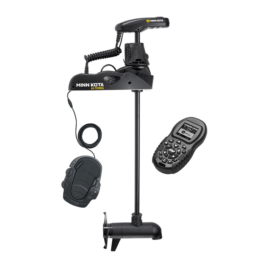
bow-mount trolling motor
Hide thumbs
Also See for ULTERRA:
- User manual ,
- Owner's manual (98 pages) ,
- Installation instructions manual (84 pages)
Table of Contents
Advertisement
Advertisement
Table of Contents

Subscribe to Our Youtube Channel
Related Manuals for MINN KOTA ULTERRA


Summary of Contents for MINN KOTA ULTERRA
- Page 1 ULTERRA™ WITH i-PILOT LINK™ ® BOW-MOUNT TROLLING MOTOR OWNER'S MANUAL...
-
Page 2: Introduction
2,5m/sec2. You are responsible for the safe and prudent operation of your vessel. We have designed Ulterra to be an accurate and reliable tool that will enhance boat operation and improve your ability to catch ish. This product does not relieve you from the responsibility for safe operation of your boat. You must avoid hazards to navigation and always maintain a permanent watch so you can respond to situations as they develop. -
Page 3: Table Of Contents
TAbLE Of CONTENTs Introduction Two-Year Limited Warranty Warranty on Minn Kota i-Pilot® and i-Pilot® Link™ Wireless GPS Trolling System Warranty on Minn Kota Freshwater Trolling Motors Humminbird Warnings Features Motor Features Control Panel Foot Pedal Mount Installation 9-14 Battery & Wiring Installation 15-16 Boat Rigging &... -
Page 4: Two-Year Limited Warranty
KOTA LImITEd TWO-YEAR WARRANTY ON THE ENTIRE PROdUCT JOME warrants to the original retail purchaser only that the purchaser’s new Minn Kota i-Pilot® or i-Pilot® Link™ Wireless GPS Trolling System Accessory will be materially free from defects in materials and workmanship appearing within two (2) years after the date of purchase. JOME will (at its option) either repair or replace, free of charge, any parts found by JOME to be defective during the term of this warranty. -
Page 5: Warranty On Minn Kota Freshwater Trolling Motors
KOTA LImITEd LIfETImE WARRANTY ON COmPOsITE sHAfT JOME warrants to the original retail purchaser only that the composite shaft of the purchaser’s Minn Kota trolling motor will be materially free from defects in materials and workmanship appearing within the original purchaser’s lifetime. JOME will provide a new composite shaft, free of charge, to replace any composite shaft found by JOME to be defective during the term of this warranty. -
Page 6: Humminbird Warnings
HUmmINbIRd WARNINGs HUmmINbIRd WARNINGs WARNING! This device should not be used as a navigational aid to prevent collision, grounding, boat damage, or personal injury. When the boat is moving, water depth may change too quickly to allow time for you to react. Always operate the boat at very slow speeds if you suspect shallow water or submerged objects. WARNING! The electronic chart in your Humminbird®... -
Page 7: Features
fEATUREs mOTOR fEATUREs Integrated i-Pilot Link Control Head Power Trim Power Stow/Deploy Lifetime Warranty Flexible Composite Shaft Multi-Function Foot pedal Cool Quiet Power Motor Weedless Wedge 2 Propeller Speciications subject to change without notice. *This diagram is for reference only and may difer from your actual motor. minnkotamotors.com | 7 ©2014 Johnson Outdoors Marine Electronics, Inc. -
Page 8: Control Panel
fEATUREs CONTROL PANEL Power Button: Press the power button to turn the motor on or of . Once power button is pressed, power will remain on for 1.5 hours in the absence of any button presses, when motor is stowed. Press and hold for two seconds to turn motor of . Status (red LED): The motor is equipped with a status indicator. -
Page 9: Mount Installation
✒ ✚ ✁ ✂ ✠ Your new Ulterra comes out of the box with everything you’ll need for direct to boat mounting. This motor can be direct mounted to the boat or coupled with a Minn Kota quick release bracket for ease of mounting and removal. - Page 10 INsTALLATION Parts Included: Description Qty. Screw, 1/4-20 x 2” HH Screw, 1/4-20 x 0.5 HH Washer-Clipped, 1/4”, 1” OD Nut, 1/4-20 Nylock SS Washer, 1/4” Flat 18-8 SS Washer-Mounting, Rubber Tools and Resources Required: • Drill • 5/16” Drill Bit •...
- Page 11 INsTALLATION 5. Mount the motor to the boat using the provided hardware. Install the hex head bolts and clipped washers on the right side of the motor as viewed from the boat interior. (Figure 5) Motor can then be slid into place utilizing the slots on the motor base plate.
- Page 12 INsTALLATION CONNECT THE i-PILOT LINK TO THE HUmmINbIRd fIsHfINdER The i-Pilot Link can be connected directly to the Humminbird Fishi nder or to the Humminbird Ethernet Switch (optional). If you purchase the Ethernet Switch, install it using the instructions in the Ethernet Accessory Guide. WARNING: The power source must be turned of before you proceed with this installation.
- Page 13 INsTALLATION VERIfYING INsTALLATION ON THE HUmmINbIRd fIsHfINdER All equipment should be connected and powered before you turn on the Fishi nder. When the i-Pilot Link is detected, i-Pilot Link Connected will display briel y on the screen. You can also coni rm the installation connections using the following instructions.
- Page 14 Turn power on and deploy motor using the stow/deploy button on footpedal or remote (see the Manual Control section or Ulterra Functions for deploying instructions). CAUTION: When deploying, ensure the motor doesn’t contact boat or trailer.
-
Page 15: Battery & Wiring Installation
CAUTION: These guidelines apply to general rigging to support your Minn Kota motor. Powering multiple motors or additional electrical devices from the same power circuit may impact the recommended conductor gauge and circuit breaker size. If you are using wire longer than that provided with your unit, follow the conductor gauge and circuit breaker sizing table below. -
Page 16: Selecting The Correct Batteries
Breaker Sizing Table” in the previous section to i nd the appropriate circuit breaker or fuse for your motor. For motors requiring a 60-amp breaker, the Minn Kota MKR-19 60-amp circuit breaker is recommended. CONNECTING THE bATTERIEs IN sERIEs (If REQUIREd fOR YOUR mOTOR) -
Page 17: Motor Wiring Diagram
Accessory Trim Module Coil Cord Cam Sensor Tilt Sensor Plunger Sensor Power On Button AutoPilot (Red) Spot-Lock (Blue) Status (Red) Ulterra Mode (Amber) Constant (Green) Power (Green) Mode Sensor Spot-Lock Sensor Speed Adjustment Foot Pedal Motor Tilt Motor Steering Module... -
Page 18: Getting Started
• Red X = motor is trimmed to the prop lockout region. ULTERRA From the Home screen, press to access Ulterra functions. Any press of the home button will take you back to the Home screen. sTOWING dEPLOYING • Prop icon is not on = prop is disabled. - Page 19 The Softkey Labels at the bottom of the LCD indicate their current function. HEADER Menu Up & Menu Down Used to navigate the menus and access the Ulterra functions. DASHBOARD Home Pressing this key will always bring up the Home Screen.
-
Page 20: Controls Menu
GETTING sTARTEd CONTROLs mENU To enter the Controls Menu, select Home > Controls Softkey CONTROLs > REsUmE When navigation is paused (Spot-Locked), selecting Resume will restart the original navigation mode. Note that this selection is only available when navigation is currently paused. CONTROLs >... - Page 21 GETTING sTARTEd CONTROLs > bACKLIGHT sETTINGs: Backlight Menu Backlight Settings > Brightness This screen allows the user to manually control the brightness of the backlight. Use the up/down arrow keys to adjust. Select the Back or Close Softkey to save the setting and exit. Backlight Settings >...
- Page 22 GETTING sTARTEd CONTROLs > CONfIGURATIONs Confi gurations menu Enter this menu by selecting Home > Controls Softkey > Coni gurations > OK Confi gurations > Restore Softkey This selection allows the user to reset the coni gurations on the remote to factory defaults. Confi...
- Page 23 GETTING sTARTEd Confi gurations > Units From this menu, the user coni gures the following: Coni guration > Units A. DEPTH Choosing this selection will bring up a list of units to use when displaying depth. Use the up/down arrow keys to select a new value and press the OK key to accept. Select the Back or Close Softkey to save the setting and exit.
-
Page 24: Remote Battery
GETTING sTARTEd REmOTE bATTERY Charging Indicator The i-Pilot Link remote contains a rechargeable battery. To charge the battery, plug the USB end into the included DC adapter and plug the other (two pronged) end into the charging port of the remote. The Charging Indicator will illuminate whenever an energized charging cable is connected. - Page 25 GETTING sTARTEd AUdIO mOdEs The i-Pilot Link Controller also contains an internal speaker which can be programmed to work in two dif erent audio modes. The speaker is programmed to operate in Audio Mode two from the factory. To select the dif erent audio modes, from the Home screen go to: Settings >...
-
Page 26: System Startup
GETTING sTARTEd POWER The i-Pilot Link controller will turn on whenever the trolling motor has power connected and has been turned on. This is when the green system ready light is on. ACCURACY The accuracy and responsiveness with which i-Pilot Link controls your boat is highly dependent upon many variables. Just a few of these variables and their general ef ects on responsiveness and accuracy are given below so that the behavior of the system can be understood. -
Page 27: Software Updates
GETTING sTARTEd sOfTWARE UPdATEs Set up an online account at humminbird.com so that you will receive the latest Humminbird news and software updates for your Fishi nder. The i-Pilot Link remote and controller software are also updated through the Humminbird Fishi nder. WARNING! Humminbird is not responsible for the loss of data i les (waypoints, routes, tracks, groups, snapshots, recordings, etc.) that may occur due to direct or indirect damage to the unit’s hardware or software. -
Page 28: Getting Started
GETTING sTARTEd 3. Update the Software 1. Install the SD card with the updated software i les into the Fishi nder card slot. 2. Fishfi nder Update: The Fishi nder will recognize the new software. Follow the dialog box instructions to coni rm software installation. -
Page 29: I-Pilot Link Setup
i-PILOT LINK sETUP sECTION TITLE i-PILOT sETUP i-PILOT LINK sETUP fROm THE HUmmINbIRd: Enable i-Pilot Link Navigation To start i-Pilot Link navigation from the Fishi nder, the i-Pilot Navigation menu option must be turned on. When i-Pilot Navigation is turned on, the related i-Pilot Link menus will be added to the menu system. -
Page 30: I-Pilot Link Setup
i-PILOT LINK sETUP From the Humminbird: Main Menu: Press the MENU key twice. 2. Select the Accessories tab > i-Pilot > Arrival Mode. 3. Press the RIGHT or LEFT Cursor keys to select Of , Spot-Lock, or AutoPilot. (Default = Of ) From the remote: From the Home screen, select the Controls Softkey >... -
Page 31: Manual Control
mANUAL CONTROL mANUAL CONTROL fUNCTIONALITY This section describes all Manual Control functions of i-Pilot Link. A manual function is one in which the operator takes full control of the function such as manually steering the motor in a desired direction or manually adjusting the prop speed to the desired setting. PROP ON/Off To turn the motor on or of press . - Page 32 mANUAL CONTROL HIGH sPEEd bYPAss OPERATION Engage From the Home screen, pressing will set the motor speed to maximum immediately. The rabbit icon will change to the revert icon Disengage There are a few ways to disengage the High Speed Bypass. Pressing (revert) will disengage the High Speed Bypass and send you back to your previous speed.
-
Page 33: Ulterra Functions
ULTERRA fUNCTIONs I NG ULTERRA fUNCTIONs UsING THE mENU CONTROL KEYs ✄ ☎ ☎ ✆ ✝ ✝ You can access the ulterra functions (Stowing & Deploying, Trimming and 12:13 PM OCT 18 PROP SPEED TARGE T High-Speed Bypass) from the home screen by pressing... - Page 34 ✤ ✞ T ERRA fUNCTIONs sTOWING THE mOTOR When the motor is fully deployed, you can press to stow the motor or press to return to the Home screen. TRImmING THE mOTOR You can also trim the motor from this screen by pressing NOTE: Trim limits are in place to avoid damage to the unit.
-
Page 35: Gps Motor Control
mOTOR WIRING dIAGRAm GPs mOTOR CONTROL UNdERsTANdING HOW THE i-PILOT LINK sYsTEm WORKs i-Pilot Link uses GPS satellite signals as well as digital compass data to know where it is, where it is heading and the direction the motor is pointing. Since i-Pilot Link depends on GPS satellite signals for navigation, a minimum GPS signal level of one bar is required in order for GPS navigation controls to be enabled. - Page 36 mOTOR CONTROL ✟ ✡ ☛ fIsHfINdER OPERATIONs OPEN THE CHART VIEW The i-Pilot Link features and Navigation X-Press menu options are displayed in the Chart View and Bird’s Eye View. To see all available i-Pilot Link navigation features, use the Chart View. Press and hold the VIEW key.
-
Page 37: Spot-Lock
sECTION TITLE sPOT-LOCK HOW sPOT LOCK-WORKs Spot-Lock uses a single point as a reference for the spot you want to stay on. Around the Spot-Lock location i-Pilot Link uses an arrival circle to determine prop speed and direction. If i-Pilot Link sees it is 12:13 PM OCT 18 within the circle, it will adjust the motor speed to zero. - Page 38 ☞ ✌ ✍ ✎ ✏ ✑ ✍ ✓ ✔ fIsHfINdER OPERATIONs ENGAGE sPOT-LOCK AT THE bOAT POsITION You can quickly Spot-Lock at the current boat position. This type of Spot-Lock is temporary, and unless you save it, the Spot-Lock will be deleted when you start a new mode of navigation. Navigation X-Press Menu: Press the MENU key.
- Page 39 ✕ ✖ ✗ ✘ ✙ ✛ ✗ ✜ ✢ mARK A sPOT-LOCK ANd sTART NAVIGATION You can mark a Spot-Lock at the cursor location and start navigation towards it automatically. When the boat reaches the point, it will Spot-Lock until you disengage it. This type of Spot-Lock is temporary. Use the 4-WAY Cursor Control key to move the cursor to a position on the chart.
-
Page 40: Waypoints
mOTOR WIRING dIAGRAm sECTION TITLE WAYPOINTs HOW WAYPOINT NAVIGATION WORKs Waypoints are stored positions that allow you to mark areas of interest or navigation points. Your Fishi nder can save a combination of up to 2,750 Waypoints and Spot-Locks. mARK A WAYPOINT To create a Waypoint at the boat’s position, press and hold the Spot-Lock key. - Page 41 Y POINTs ✣ ✥ NAVIGATE TO THE mOsT RECENTLY CREATEd WAYPOINT Navigation X-Press Menu: Press the MENU key. 2. Select the Waypoint name (WP), and press the RIGHT Cursor key to open the submenu. 3. Select Go To, and press the RIGHT Cursor key to start navigation. NOTE: Waypoints are saved with an alphanumeric name that stars with WP.
-
Page 42: Itracks
mOTOR WIRING dIAGRAm sECTION TITLE iTRACKs HOW iTRACK RECORdING ANd NAVIGATION WORK When the recording of an iTrack is initiated, i-Pilot Link starts to record GPS position data in the form of track points. The distance between these points varies based on the speed of the boat and the GPS signal strength. The very i rst track point recorded is called the Start. - Page 43 iTRACK REmOTE OPERATIONs RECORdING AN iTRACK To begin recording, select Home > Controls > Record > OK 12:13 PM OCT 18 PROP S PE E D TARG E T 2. To stop the recording, press the StopRec Softkey on the iTrack DE PT H B E AR I NG D IS TA N C E...
- Page 44 iTRACKs fIsHfINdER OPERATIONs RECORd AN iTRACK Main Menu: Press the MENU key twice. 2. Select the Accessories tab. 3. Select Record iTrack, and press the RIGHT Cursor key. 4. Press the EXIT key until the menu system is closed. As you navigate, the iTrack Recording Icon will l ash on the screen periodically to indicate that a recording is in progress.
- Page 45 iTRACKs NAVIGATE A sAVEd iTRACK fROm THE GO TO LIsT Press the GO TO key. 2. Select an iTrack Start or iTrack End from the Go To list. Press the RIGHT Cursor key. REVERsE dIRECTION dURING iTRACK NAVIGATION If you are navigating a saved iTrack, you can quickly change the navigation direction toward the Start Point or End Point.
- Page 46 iTRACKs Selecting a Saved iTrack from the Go To List Go To List Starts navigation to the nearest iTrack point and i nishes at the Start Point Starts navigation to the nearest iTrack point and i nishes at the End Point Open the Select a Saved iTrack Go To List...
-
Page 47: Backtrack
bACKTRACK HOW bACKTRACK WORKs Traditional Humminbird tracks consist of detailed position history and are displayed as a breadcrumb trail of trackpoints. The Current Track shows the position history since the unit was powered up. You can clear the Current Track or save it at any time. The Current Track represents your actual path so far. BackTrack allows you to navigate the Current Track as a recorded iTrack. -
Page 48: Follow The Contour
FOLLOW THE CONTOUR HOW fOLLOW THE CONTOUR WORKs (CHART VIEW ONLY, i-PILOT COMPATIBLE HUMMINBIRD LAKEMASTER OR AUTOCHART SD CARD REQUIRED) Follow the Contour allows you to navigate a contour on a LakeMaster chart. When you start i-Pilot Link navigation to Follow the Contour, all other types of navigation are stopped on the Fishi nder and the Ethernet network. - Page 49 fOLLOW THE CONTOUR Starting Follow the Contour Navigation Submenu Navigation Option 1 (orange) Contour Line(s) Navigation Option 2 (blue) Navigation Option 1 (previewed in orange) Boat Icon (idle) Cursor selecting a contour Navigation Option 2 (previewed in blue) Move the Cursor Open the Contour Select a Menu Option Submenu...
-
Page 50: Follow The Contour
fOLLOW THE CONTOUR sET THE CONTOUR OffsET If you don’t want to navigate on the contour line, you can set a distance from the contour so that navigation will be of set from the selected contour. Use the 4-WAY Cursor Control key to move the cursor to a contour line. 2. -
Page 51: Route Navigation
ROUTE NAVIGATION HOW ROUTE NAVIGATION WORKs Routes link two or more waypoints together to create a path for navigation and are used in trip planning. Your Fishi nder can store up to 45 routes that can each contain up to 50 waypoints. A route represents your intended navigation and shows the shortest path from each waypoint to the next. - Page 52 ROUTE NAVIGATION fIsHfINdER OPERATIONs CREATE A ROUTE In a Chart View, use the 4-WAY Cursor Control key to select a waypoint, Spot-Lock, or position on the chart. 2. Press the GO TO key. 3. To add more waypoints or Spot-Locks to the route, repeat steps 1 and 2. NOTE: If the position you select is also a Contour Line, a submenu will open with related menu options.
-
Page 53: Autopilot /Advanced Autopilot
mOTOR WIRING dIAGRAm AUTOPILOT HOW AUTOPILOT WORKs Two dif erent versions of AutoPilot are available Advanced AutoPilot and Legacy AutoPilot. There are distinct dif erences between the two AutoPilots and how they control your boat. AdVANCEd AUTOPILOT Advanced AutoPilot not only uses compass heading but also GPS signal data to correct for cross winds, current and other external forces to keep the boat on a straight line. - Page 54 AUTOPILOT 54 | minnkotamotors.com 54 | minnkotamotors.com ©2014 Johnson Outdoors Marine Electronics, Inc.
- Page 55 AUTOPILOT minnkotamotors.com | 55 ©2014 Johnson Outdoors Marine Electronics, Inc.
- Page 56 AUTOPILOT sELECTING AUTOPILOT mOdEs The user can choose between Advanced AutoPilot and Legacy AutoPilot either from the remote or from the Humminbird. fROm THE REmOTE: Home > Controls Softkey > AutoPilot Mode ENGAGING AUTOPILOT To engage AutoPilot, press the AutoPilot key 2.
- Page 57 AUTOPILOT Adjusting the AutoPilot Heading Adjustment Preview Line (purple) The AutoPilot Heading Line can be turned on or of . The yellow AutoPilot icon indicates AutoPilot Mode is set to Advanced. Adjust Coni rm Heading dIsPLAY OR HIdE THE AUTOPILOT HEAdING LINE Main Menu: Press the MENU key twice.
-
Page 58: Cruise Control
CRUIsE CONTROL HOW CRUIsE CONTROL WORKs i-Pilot Link’s Cruise Control automatically sets the prop speed to maintain constant GPS speed. Because this controls only the prop speed, Cruise Control can be used in conjunction with AutoPilot and iTrack Record as well as with navigating iTracks, LakeMaster contour lines, routes, and waypoints. -
Page 59: Data Management
mOTOR WIRING dIAGRAm dATA mANAGEmENT mANAGE YOUR i-PILOT LINK NAVIGATION dATA You can edit iTracks and Spot-Locks in the Waypoint Management dialog box in the same way that you can edit other Humminbird navigation data. You can also create new iTracks and Spot-Locks, and you can start navigation to the selected item. - Page 60 A mANAGEmENT ✦ ✧ ★ EdIT AN iTRACK OR A sPOT-LOCK Select a Spot-Lock or iTrack, and press the RIGHT Cursor key. 2. Select Edit from the submenu, and press the RIGHT Cursor key. 3. Use the 4-WAY Cursor Control key to move from i eld to i eld, and press the UP or DOWN Cursor keys to change the settings.
- Page 61 A mANAGEmENT ✩ ✪ ✫ WARNING! Humminbird is not responsible for the loss of data i les (waypoints, routes, tracks, groups, snapshots, recordings, etc.) that may occur due to direct or indirect damage to the unit’s hardware or software. It is important to back up your Fishi nder’s data i les periodically.
- Page 62 A mANAGEmENT ✬ ✭ ✮ EXPORT TO AN sd CARd Your saved iTracks and Spot-Locks should be backed up periodically along with your other navigation data (waypoints, routes, tracks). Export your navigation items to an unlocked, installed SD card, and they can also be managed in HumminbirdPC.
-
Page 63: Using Your Foot Pedal
ING YOUR fOOTPEdAL ULTERRA fUNCTIONs Pressing the MODE button allows the use of the Ulterra speciic AUTOPILOT sPOT-LOCK functions. You can steer (heel/toe), trim or stow/deploy the motor while in Ulterra mode. mOdE CONsTANT TRIm UP/dOWN To trim up/down: Push the mode button until the center yellow... - Page 64 I NG YOUR fOOTPEdAL ✯ ✰ PROP ON All Prop On functions can be used in Standard and Ulterra Mode. AUTOPILOT sPOT-LOCK NOTE: Prop button switches to Stow/Deploy in Ulterra Mode. mOdE mOmENTARY bUTTON To operate the motor in momentary mode: Pressing either of the...
- Page 65 ✱ ✲ sPEEd AdJUsT To adjust motor speed: Rotate the speed knob on the right side of the pedal to the desired speed setting. You can adjust the speed in Standard and Ulterra mode. sPOT-LOCK AUTOPILOT sPOT-LOCK To initiate Spot-Lock: Pressing the Spot-Lock button initiates...
-
Page 66: Emergency Stow Procedure
mERGENCY sTOW PROCEdURE In the event of a power loss the following procedure shall be used to stow the motor for transport to a service center. Remove right hand sideplate using a Phillips screwdriver. (Figure 13) Figure 13 2. Using a Phillips screwdriver, loosen the screw on the manual tilt knob and then pry up with a l at blade screwdriver until it releases from the metal plates. - Page 67 ✳ m ERGENCY sTOW PROCEdURE 4. While pulling up on the bracket to release the latch pin, rotate (Figure 17) and pull the lower unit onto the ramps. (Figure 18 & Figure 19) Figure 17 Figure 18 Figure 19 5. Secure lower unit onto the ramps using the provided emergency strap. The d-ring on the emergency strap can be hooked into the base as shown (Figure 20).
-
Page 68: Adjustments
mENTs AdJUsTING THE LIfT bELT Periodically slack may appear in the main lift belt, and it may occasionally require small adjustments to maintain belt tension. Using a 1/8” allen wrench turn the socket head cap screw, located on the bottom of the control head, clockwise (see Figure 22) until belt is inger tight and you can force inger under belt. -
Page 69: Service & Maintenance
sERVICE & mAINTENANCE sERVICE & mAINTENANCE PROPELLER REPLACEmENT TOOLS AND RESOURCES REQUIRED: Propeller • Box End Wrench Slot End - 1/2” for motors with 70 lbs thrust or lower. - 9/16” for motors with 80 lbs thrust or higher. Prop Nut Washer •... -
Page 70: Troubleshooting
bLEsHOOTING ✴ ✵ ✶ ✷ ✸ ✸ ✹ Motor fails to run or lacks power: • Check battery connections for proper polarity. • Are batteries charged? • Make sure terminals and wires are clean and corrosion free. Use i ne sandpaper or emery cloth to clean terminals. •... - Page 71 b LEsHOOTING ✺ ✻ ✼ ✽ i-PILOT LINK GENERAL TROUbLEsHOOTING Problem: The motor is making erratic steering corrections while in AutoPilot, Spot-Lock or Track to Start/End. Solution: Be sure to keep all ferrous metallic objects away from the i-Pilot Link controller as they will have an impact on the built-in compass.
- Page 72 AUTHORIZEd sERVICE CENTERs Minn Kota has over 300 authorized service centers in the United States and Canada where you can purchase parts or get your products repaired. Please visit our Authorized Service Center page on our website to locate a service center in your area.
-
Page 73: Frequently Asked Questions
Q: What is the “Mode” button on the foot pedal? The Ulterra foot pedal is dual function. When it is in “Ulterra” mode, the yellow LED light will be illuminated. In this state the foot pedal toe buttons can be used to auto stow and deploy the motor and control trim. When it is in “steering” mode, the yellow LED will be of . - Page 74 Polarized sunglasses can dramatically af ect the way an LCD looks to the human eye. Where can I purchase additional remotes? Your local Minn Kota retailer should carry additional remotes. If I turn of the remote, will i-Pilot Link continue to operate? Yes.
-
Page 75: Parts Diagram
PARTs dIAGRAm s dIAGRAm minnkotamotors.com | 75 ©2014 Johnson Outdoors Marine Electronics, Inc. - Page 76 s dIAGRAm 24 Volt Motor 36 Volt Motor 76 | minnkotamotors.com ©2014 Johnson Outdoors Marine Electronics, Inc.
-
Page 77: Parts List
s dIAGRAm ❂ ❃ ❄ ❅ PARTs LIsT ITEm PART NUmbER dEsCRIPTION ITEm PART NUmbER dEsCRIPTION 2777016 24 V MOTOR 45" FW 2200000 BEARING-THRU , NEEDLE 2777015 24V MOTOR 60" FW 2207300 BUSHING, TRIM, TOP 2777086 36V MOTOR 45" FW 2206525 HOUSING-TRIM, GEAR SIDE 2777085... - Page 78 s dIAGRAm ❆ ❇ ❈ ❉ PARTs LIsT ITEm PART NUmbER dEsCRIPTION ITEm PART NUmbER dEsCRIPTION 2203911 RAMP-MOTOR, RIGHT, 80# 2994171 REMOTE SY, IPILOT 1.5 2203910 RAMP-MOTOR, RIGHT, 112# 2994180 REMOTE SY, IPILOT LINK *LINK ONLY* 2206550 HOUSING, CONNE OR WPJ 2370817 NYARD, REMOTE W/ RABEENER...
- Page 79 s dIAGRAm ❊ ❋ ● ❍ PARTs LIsT sERVICE KITs dEsCRIPTION PART NO. ITEm NUmbER INCLUdEd / QUANTITY TRIM MOTOR 2777810 87 (1), 89 (1), 90 (1), 91 (2), 92(1), 93 (1) TILT BRACK 2774201 50 (1), 51 (1), 112 (4), 113 (1), 114 (2), 115 (1), 116 (1) OUTPUT GEAR W/ MAGN S 2772200 31 (1), 192 (4)
-
Page 80: Compliance Statements
Minn Kota motors are not subject to the disposal regulations EAG-VO (electric devices directive) that implements the WEEE directive. Nevertheless never dispose of your Minn Kota motor in a garbage bin but at the proper place of collection of your local town council. -
Page 81: Compliance Statements
COmPLIANCE sTATEmENTs fCC COmPLIANCE This device complies with Part 15 of the FCC rules. Operation is subject to the following two conditions: This device may not cause harmful interference. 2. This device must accept any interference that may be received, including interference that may cause undesired operation. Changes or modiications not expressly approved by Johnson Outdoors Marine Electronics, Inc. - Page 82 Stop buying new batteries and start taking care of the ones you’ve got. Many chargers can actually damage your battery over time – creating shorter run times and shorter overall life. Digitally controlled Minn Kota chargers are designed to provide the fastest charge that protect and extend battery life.
Need help?
Do you have a question about the ULTERRA and is the answer not in the manual?
Questions and answers
I have an altera I-Pilot trolling motor. it depoys and stows fine but does not trim down. is there any possible settings that would stop this function.
The trim function on a Minn Kota Ulterra I-Pilot trolling motor may not work if:
1. The motor is in the prop lockout region (17" from bottom of motor mount to center of motor), which disables all functions except manual steer and track record.
2. There is a need for recalibration due to malfunction. This can be resolved by turning the motor off, waiting 3 seconds, then pressing the power button 3 times within 2 seconds to initiate recalibration.
3. There is excessive friction or mechanical resistance, which can be reduced by applying grease to the necessary parts.
These settings or conditions can prevent proper trim function.
This answer is automatically generated