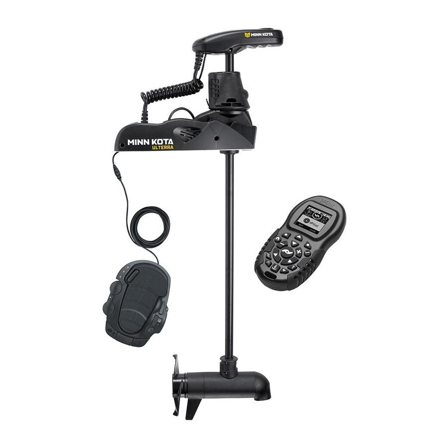
MINN KOTA ULTERRA Installation Instructions Manual
Bow-mount trolling motor
Hide thumbs
Also See for ULTERRA:
- User manual ,
- Owner's manual (98 pages) ,
- Installation instructions manual (68 pages)
Table of Contents
Advertisement
Available languages
Available languages
Quick Links
Advertisement
Table of Contents

Related Manuals for MINN KOTA ULTERRA


Summary of Contents for MINN KOTA ULTERRA
- Page 1 ULTERRA™ BOW-MOUNT TROLLING MOTOR Installation Instructions...
-
Page 2: Motor Information
Thank you for choosing Minn Kota. We believe that you should spend more time fishing and less time positioning your boat. That’s why we build the smartest, toughest, most intuitive trolling motors on the water. Every aspect of a Minn Kota trolling motor is thought out and rethought until it’s good enough to bear our name. -
Page 3: Safety Considerations
WARNING You are responsible for the safe and prudent operation of your vessel. We have designed your Minn Kota product to be an accurate and reliable tool that will enhance boat operation and improve your ability to catch fish. This product does not relieve you from the responsibility for safe operation of your boat. -
Page 4: Know Your Boat
KNOW YOUR BOAT Starboard Starboard Port Port Inboard Inboard Outboard Outboard Keel Keel Port Port Starboard Starboard Gunwale Gunwale Transom Transom Stern Stern Gunwale Gunwale Stern Stern Hull Hull 4 | minnkota.johnsonoutdoors.com ©2023 Johnson Outdoors Marine Electronics, Inc. -
Page 5: Installation
INSTALLING THE ULTERRA Your new Ulterra comes with everything you’ll need to directly install it to the boat. This motor can be directly mounted to the boat or it may be coupled with a Minn Kota quick release bracket for ease of mounting and removal. For installation with a quick release bracket, refer to the installation instructions provided with the bracket. - Page 6 Screw Screw Screw Screw Screw Screw NOTICE: This motor weighs approximately 70 lbs. Minn Kota recommends having a second person help with Stowed Stowed Deployed Deployed the installation. Remove the Right Sideplate to access the Mounting Slots. Remove the Left Sideplate to access the Mounting Holes.
- Page 7 Deck of Boat NOTICE: The Emergency Strap (Item #9) is used for manually stowing the Ulterra. The Emergency Strap is not secured during installation. Store it on your boat in the event that you would need to manually stow the motor.
- Page 8 INSTALLING THE ULTERRA ITEM(S) NEEDED #8 x 6 WARNING NOTICE: Failure to allow 1-1/2" of clearance for the Shaft when mounting may cause failures when the motor stows and deploys. Follow recommended mounting considerations Illustrations are for reference only. Do not deploy the motor to avoid obstructions when operating the motor.
- Page 9 NOTICE: The Short Bolts (Item #4) are only used when installing the Ulterra to a quick release bracket. If installing the Ulterra to a quick release bracket, please refer to the instructions that came with the bracket for more information. Quick release bracket installation instructions can also be viewed online at minnkota.johnsonoutdoors.com.
- Page 10 NOTICE: The Short Bolts (Item #4) are only used Washer Washer when installing the Ulterra to a quick release bracket. If installing the Ulterra to a quick release Mounting Mounting Holes Holes bracket, please refer to the instructions that came...
- Page 11 INSTALLING THE ULTERRA At this point in the installation process, the Motor should be secured to the deck of the boat and can now be reassembled. The Extension Damper can be slid back in place on the Damper Pins. This should...
- Page 12 Feature & Cable Identification The Ulterra is pre-installed with Advanced GPS Navigation - including the ability to connect via Ethernet to a Humminbird unit. It is also installed with sonar, either Dual Spectrum CHIRP or Built-in MEGA Down Imaging. Dual Spectrum CHIRP and Built-in MEGA Down Imaging will be installed in combination with Advanced GPS Navigation.
- Page 13 FEATURE & CABLE MANAGEMENT Feature & Cable Management DUAL SPECTRUM CHIRP Your trolling motor may be pre-installed with a transducer system Dual Spectrum CHIRP featuring Humminbird’s Dual Spectrum CHIRP. CHIRP stands for “Compressed High Intensity Radar Pulse.” Dual Spectrum CHIRP is a 2D sonar transducer with a temperature sensor that is integrated into the lower unit of the trolling motor.
- Page 14 DUAL SPECTRUM CHIRP The integrated design of the Dual Spectrum CHIRP transducer protects it in the lower unit of the trolling motor from underwater hazards and prevents tangles and damage to the transducer cables. In certain situations, air bubbles may adhere to the surface of the Dual Spectrum CHIRP transducer and affect the performance.
- Page 15 If using cable ties, do not over-tighten. Any excess cable should be bundled in a loose loop of no less than 4” in diameter. The connection cable should be routed to the fish finder following Minn Kota recommendations on routing the cables to optimize mobility and maximize functionality.
- Page 16 DUAL SPECTRUM CHIRP If installing directly to a Solix or Apex, the connection Fourteen Pin Fourteen Pin will be flat on the back of the fish finder display. Connector Connector Align the pins on the Accessory Cable with the Dual Spectrum CHIRP Dual Spectrum CHIRP Solix or Apex Solix or Apex...
- Page 17 DUAL SPECTRUM CHIRP ITEM(S) NEEDED #22 x 1 If installing directly to a Helix Adapter Cable, align Fourteen Pin Fourteen Pin Receptacle Receptacle the pins on the accessory cable or extension cable Connector Connector with the receptacle on the Helix Adapter Cable (Item #22).
- Page 18 BUILT-IN MEGA DOWN IMAGING BUILT-IN MEGA DOWN IMAGING Built-in MEGA Down Imaging delivers nearly 3X the output of standard Side Imaging®, and takes fishfinding into the megahertz frequency for the very first time. It uses a razor-thin, high-frequency beam to create picture-like images of structure, vegetation and fish. With Humminbird MEGA imaging sonar built right into the trolling motor, you now have a crystal clear view of what’s directly beneath the boat, without having to manage all of the cables that come with external transducers.
- Page 19 BUILT-IN MEGA DOWN IMAGING CAUTION Failure to follow the recommended wire routing for installed features, if equipped, may cause damage to the product and void your product warranty. Route cables away from pinch points or other areas that may cause them to bend in sharp angles. Routing the cables in any way other than directed may cause damage to the cables by being pinched or severed.
- Page 20 BUILT-IN MEGA DOWN IMAGING If installing directly to a Solix or Apex, the connection Fourteen Pin Fourteen Pin will be flat on the back of the fish finder display. Connector Connector Align the pins on the Accessory Cable with the Built-in MEGA Down Built-in MEGA Down Solix or Apex...
- Page 21 BUILT-IN MEGA DOWN IMAGING ITEM(S) NEEDED #22 x 1 If installing directly to a Helix Adapter Cable, align 4h Fourteen Pin Fourteen Pin Receptacle Receptacle the pins on the accessory cable or extension cable Connector Connector with the receptacle on the Helix Adapter Cable (Item #22).
- Page 22 ADvANCED GPS NAvIGATION Your Minn Kota trolling motor and Humminbird fish finder communicate with each other to change the way you fish. Advanced GPS Navigation offers a large array of features including controlling speed, steering, Spot-Lock, and the ability to record and retrace paths on the water, all at your fingertips.
- Page 23 Leads Leads Foot Pedal Foot Pedal NOTICE: Ulterra trolling motors with Advanced GPS Power Connector Power Connector Navigation are also equipped with Sonar. Sonar is pre-installed from the factory and may be either Dual Spectrum CHIRP or Built-in MEGA Down Imaging. A Sonar Cable will be present below the Control Head and run through the center of the Coil Cord.
- Page 24 ADvANCED GPS NAvIGATION ITEM(S) NEEDED #15 x 1 Identify the keyed Receptacle on the Ethernet Eight Pin Eight Pin Control Head Control Head Cable (Item #15). It will be keyed to fit with the Eight Connector Connector Pin Advanced GPS Ethernet Connector below the Ethernet Cable Ethernet Cable Control Head.
- Page 25 ADvANCED GPS NAvIGATION To install the Ethernet Cable, align the pins on Eight Pin Eight Pin the Advanced GPS Ethernet Connector with the Receptacle Receptacle Connector Connector Receptacle on the Ethernet Cable. Notice the keyed connectors. Tighten the Collar from the Ethernet Cable to secure the connection.
- Page 26 Cable Cable Cable to secure the connection. Helix Adapter Cable Helix Adapter Cable NOTICE: Minn Kota provides one Helix Adapter Cable (AS EC QDE - Ethernet Adapter Cable - 720074-1) with every trolling motor equipped with Advanced GPS Navigation. Ethernet...
- Page 27 SECURING ACCESSORY CABLES Securing Accessory Cables Before securing the cables, please review the "Identifying Trolling NOTICE: If only one cable is present below the Control Motor Features and Their Associated Cables" section of this Head, this installation is not applicable. document.
- Page 28 SECURING ACCESSORY CABLES Place the motor in the stowed position. Confirm all Accessory Cables are connected to an output device as desired. Ensure the Accessory Cables are parallel to each Control Head Control Head other inside the Coil Cord. Run the Accessory Cables Pre-installed Pre-installed from the Control Head to the Mount, keeping them...
- Page 29 SECURING ACCESSORY CABLES Follow the Accessory Cables from the Control Head to the Mount and place additional Cable Ties every Cable Tie Cable Tie 4 inches. The number of Cable Ties needed will vary depending on the length of the trolling motor Shaft. Approximately Approximately 4 inches...
- Page 30 INSTALLING THE PROP Installing the Prop CAUTION Drive Drive Shipping Shipping Prop Prop Washer Washer Disconnect the motor from the battery before (discard) (discard) beginning any prop work or maintenance. While holding the Shipping Spacer with a pliers or vise grip, remove the Prop Nut, Red Shipping Washer, Prop Washer and Spacer, being careful Prop Prop...
- Page 31 Indicator ULTERRA On the Foot Pedal, press the MODE Button until the amber LED in the center of the Indicator Panel on the Foot Pedal is illuminated. This puts the Foot Pedal in Ulterra Mode. MODE MODE AUTOPILOT SPOT-LOCK MODE...
- Page 32 STOWING AND DEPLOYING THE MOTOR WITH THE ONE-BOAT NETWORK APP Minn Kota trolling motors equipped with Advanced GPS Navigation are compatible with devices enabled with the One-Boat Network®. The One-Boat Network (OBN) app is a free iOS and Android application that you can download to a mobile device, providing unparalleled control over all your One-Boat Network®...
- Page 33 STOWING AND DEPLOYING THE MOTOR WITH THE ONE-BOAT NETWORK APP Deploying the Motor with the One-Boat Network App Open the OBN app on the mobile device. From the OBN home screen, tap on the Motor menu. Before the Motor app home screen will open, select Agree on the on-screen prompt.
- Page 34 STOWING AND DEPLOYING THE MOTOR WITH THE WIRELESS REMOTE The Advanced GPS Navigation Wireless Remote comes paired from the factory to the Ulterra. To learn more about Wireless Remote features, please view the Advanced GPS Navigation Wireless Remote owner's manual online at minnkota.johnsonoutdoors.com.
- Page 35 STOWING AND DEPLOYING THE MOTOR WITH THE WIRELESS REMOTE Stowing the Motor with the Wireless Remote Open the Ulterra menu. Use the Steer Right button to select Stow. Once selected, the motor will automatically stow and the Prop will be disabled.
-
Page 36: Battery & Wiring Installation
CAUTION These guidelines apply to general rigging to support your Minn Kota motor. Powering multiple motors or additional electrical devices from the same power circuit may impact the recommended conductor gauge and circuit breaker size. If you are using wire longer than that provided with your unit, follow the conductor gauge and circuit breaker sizing table below. -
Page 37: Selecting The Correct Batteries
(flooded, AGM or GEL). Lithium-ion batteries maintain higher voltages for longer periods of time than lead acid. Therefore, running a Minn Kota trolling motor at speeds higher than 85% for a prolonged period could cause permanent damage to the motor. - Page 38 CONNECTING THE BATTERIES IN SERIES The negative (-) connection must be connected to the negative terminal of the same battery that the trolling motor negative lead connects to. In the diagrams below this battery is labeled “Low Side” Battery. Connecting to any other trolling motor battery will input positive voltage into the “ground”...
- Page 39 Keep leadwire wing nut connections tight and solid to battery terminals. • Locate battery in a ventilated compartment. This completes the installation of your Ulterra. A complete Owner’s Manual can be downloaded at minnkota.johnsonoutdoors.com. ©2023 Johnson Outdoors Marine Electronics, Inc.
-
Page 40: Recommended Accessories
Stop buying new batteries and start taking care of the ones you’ve got. Many chargers can actually damage your battery over time – creating shorter run times and shorter overall life. Digitally controlled Minn Kota chargers are designed to provide the fastest charge that protect and extend battery life. MK212PCL... - Page 41 ULTERRA™ MOTEUR DE PÊCHE À LA TRAÎNE MONTÉ SUR PROUE Instructions d’Installation...
-
Page 42: Numéro De Série
C’est pourquoi nous construisons les moteurs de pêche à la traîne les plus intelligents, les plus solides et les plus faciles à utiliser. Chaque aspect d’un moteur de pêche à la traîne Minn Kota est réfléchi et étudié jusqu’à ce qu’il soit digne de porter notre nom. Nous avons investi des heures incalculables de recherche et d’essais pour vous offrir les avantages caractéristiques de Minn Kota, qui vous mène vraiment «... -
Page 43: Consignes De Sécurité
AvERTISSEMENT Vous seul êtes responsable de la navigation sécuritaire et prudente de votre bateau. Nous avons conçu votre produit Minn Kota pour qu’il soit un outil précis et fiable qui vous permettra d’améliorer l’utilisation de votre bateau et d’accroître votre capacité de pêcher des poissons. Ce produit ne vous exonère pas de la responsabilité... -
Page 44: Connaissez Votre Bateau
CONNAISSEZ VOTRE BATEAU Étrave Étrave Bâbord Bâbord Tribord Tribord En-bord En-bord Hors-bord Hors-bord Quille Quille Bâbord Bâbord Tribord Tribord Plat-bord Plat-bord Tableau Arrière Tableau Arrière Poupe Poupe Plat-bord Plat-bord Étrave Étrave Poupe Poupe Coque Coque 44 | minnkota.johnsonoutdoors.com ©2023 Johnson Outdoors Marine Electronics, Inc. -
Page 45: Installation
INSTALLATION DE L’ULTERRA Votre nouveau Ulterra est offert avec tout ce dont vous aurez besoin pour le montage au bateau. Ce moteur peut être fixé directement sur le bateau ou couplé avec un support à dégagement rapide Minn Kota pour un montage et un démontage simples. Pour l’installation avec un support à dégagement rapide, consultez les directives d’installation fournies avec le support. - Page 46 INSTALLATION DE L’ULTERRA FACTEURS DE MONTAGE Il est recommandé que le moteur soit monté aussi près que possible de la quille ou de l’axe du bateau. Assurez-vous que la zone sous l’emplacement de montage est dégagée afin de Découvrez les accessoires pouvoir percer les trous et installer les rondelles et les écrous.
- Page 47 Pont du bateau la section « Installation ». AVIS : La sangle d’urgence (article nº 9) est utilisée pour arrimer manuellement le moteur Ulterra. La sangle d’urgence n’est pas fixée pendant l’installation. Rangez- Quille Quille la sur votre bateau au cas où vous en auriez besoin pour arrimer manuellement le moteur.
- Page 48 INSTALLATION DE L’ULTERRA ARTICLE(S) REQUIS #8 x 6 AvERTISSEMENT AVIS : Ne pas laisser un dégagement de 1 1/2 po (3,8 cm) pour l’arbre lors du montage peut causer des défaillances lors de l’arrimage et du déploiement du moteur. Veuillez Les illustrations sont à...
- Page 49 AVIS : Les boulons courts (article nº 4) ne sont utilisés que pour installer l’Ulterra sur un support à dégagement rapide. Si vous installez l’Ulterra sur un support à dégagement rapide, veuillez consulter les instructions fournies avec le support pour davantage d’informations. Les instructions d’installation du support à...
- Page 50 Serrez à l’aide d’une clé polygonale de 7/16 po (11,1 mm). Rondelle Rondelle taillée taillée AVIS : Les boulons courts (article nº 4) ne sont utilisés que pour installer l’Ulterra sur un support à Trous de Trous de montage montage dégagement rapide. Si vous installez l’Ulterra sur un Rondelle en Rondelle en support à...
- Page 51 INSTALLATION DE L’ULTERRA À ce stade du processus d’installation, le moteur devrait être fixé au pont du bateau; le moteur peut maintenant être réassemblé. La prolongation de l’amortisseur peut être glissée à sa place sur les Tige Tige tiges d’amortisseur. Cela doit se faire de façon à ce d’amortisseur...
- Page 52 Identification des fonctionnalités et des câbles L’Ulterra est préinstallé avec la navigation GPS avancée – y compris la possibilité de se connecter par le biais d’Ethernet à une unité Humminbird. Il est également installé avec un Sonar, soit le CHIRP à double spectre ou le Down Imaging MEGA intégré. Le système de navigation à...
- Page 53 ACHEMINEMENT DES CÂBLES ESSENTIELS CHIRP à double spectre ou Down Imaging MEGA intégré est CHIRP à double spectre Down Imaging MEGA intégré préinstallé sur votre moteur de pêche à la traîne. Un câble accessoire Sonar sortira de la base de la tête de commande et passera au centre du cordon enroulé.
- Page 54 GESTION DES FONCTIONNALITÉS ET DES CÂBLES Gestion des fonctionnalités et des câbles CHIRP À DOUBLE SPECTRE Votre moteur de pêche à la traîne peut être préinstallé avec un système CHIRP à double spectre de transducteur doté du CHIRP à double spectre de Humminbird. CHIRP signifie «...
- Page 55 CHIRP À DOUBLE SPECTRE La conception intégrée du transducteur CHIRP à double spectre le protège dans l’unité inférieure du moteur de pêche à la traîne contre les dangers sous-marins et évite les enchevêtrements et les dommages aux câbles du transducteur. Dans certains cas, des bulles d’air peuvent adhérer à...
- Page 56 CHIRP À DOUBLE SPECTRE Tous les moteurs CHIRP à double spectre Ulterra sont équipés d’un fil de liaison interne. Un mauvais raccordement risque de causer des interférences Sonar et peut endommager votre moteur de pêche à la traîne, vos composants électroniques et d’autres accessoires du bateau.
- Page 57 CHIRP À DOUBLE SPECTRE Vérifiez la longueur de l’arbre de votre moteur pour Arbre de 60 po (152 cm) Arbre de 45 po (114 cm) déterminer si l’acheminement des câbles essentiels Navigation GPS Navigation GPS s’applique à votre moteur de pêche à la traîne. Si l’arbre avancée avancée du moteur de pêche à...
- Page 58 DOWN IMAGING MEGA INTÉGRÉ ARTICLE(S) REQUIS #22 ou 23 x 1 Si vous installez directement sur un câble adaptateur Connecteur Connecteur Prise Prise à quatorze à quatorze Helix, enlignez les broches du câble accessoire ou du broches broches câble d’extension et la prise du câble adaptateur Helix (article nº...
- Page 59 DOWN IMAGING MEGA INTÉGRÉ Considérations relatives à la connexion et au routage du Down Imaging MEGA intégré Si le Down Imaging MEGA intégré est préinstallé sur votre moteur de pêche à la traîne, un câble d’accessoire Down Imaging MEGA intégré sortira de la base de la tête de contrôle et descendra au centre du cordon enroulé.
- Page 60 DOWN IMAGING MEGA INTÉGRÉ ATTENTION Le non-respect de l’acheminement des câbles recommandé pour les fonctionnalités installées, le cas échéant, peut endommager le produit et annuler la garantie de votre produit. Acheminez les câbles en évitant les points de pincement et les autres zones qui pourraient faire en sorte que les câbles soient pliés à...
- Page 61 DOWN IMAGING MEGA INTÉGRÉ Si vous installez directement sur un Solix ou un Apex, Connecteur à Connecteur à la connexion sera plate à l’arrière de l’écran du détecteur quatorze broches quatorze broches de poissons. Détecteur Détecteur de poissons de poissons Alignez les broches du câble accessoire avec la prise du Câble accessoire Down Imaging Câble accessoire Down Imaging...
- Page 62 DOWN IMAGING MEGA INTÉGRÉ ARTICLE(S) REQUIS #22 x 1 Si vous installez directement sur un câble adaptateur Prise Prise Connecteur à Connecteur à Helix, enlignez les broches du câble accessoire ou du quatorze broches quatorze broches câble d’extension et la prise du câble adaptateur Helix (article nº...
- Page 63 NAvIGATION GPS AvANCÉE Votre moteur de pêche à la traîne Minn Kota et le détecteur de poissons Humminbird communiquent entre eux pour changer votre façon de pêcher. La navigation GPS avancée offre un large éventail de fonctionnalités, notamment le contrôle de la vitesse, de la direction, de Spot-Lock et de la possibilité...
- Page 64 à côté du cordon enroulé. Cordon Cordon enroulé enroulé AVIS : Les moteurs de pêche à la traîne Ulterra avec navigation GPS avancée sont également équipés d’un Sonar. Le Sonar est préinstallé en usine et peut Câbles Câbles d’alimentation d’alimentation...
- Page 65 NAvIGATION GPS AvANCÉE ARTICLE(S) REQUIS #15 x 1 Identifiez la prise codée sur le câble Ethernet Tête de contrôle Tête de contrôle Connecteur Connecteur (article nº 15). Il sera codé pour s’adapter au Ethernet GPS Ethernet GPS Connecteur Connecteur connecteur Ethernet GPS avancé à huit broches avancé...
- Page 66 NAvIGATION GPS AvANCÉE Prenez le câble du Sonar et déroulez-le de l’intérieur Tête de contrôle Tête de contrôle du cordon enroulé, en progressant du support vers la tête de contrôle. Une fois desserré, le câble du Sonar sera parallèle au cordon enroulé, mais pendra Connecteur Ethernet Connecteur Ethernet GPS avancé...
- Page 67 Ethernet pour sécuriser la connexion. Helix Helix AVIS : Minn Kota fournit un câble adaptateur Helix (AS EC QDE – câble adaptateur Ethernet – 720074-1) avec chaque moteur de pêche à la traîne équipé de la navigation GPS avancée.
- Page 68 FIXATION DES CÂBLES ACCESSOIRES Fixation des câbles accessoires Avant de fixer les câbles, veuillez consulter la section « Identification des caractéristiques du moteur de pêche à la traîne et de leurs câbles associés » de ce document. Lors de l’identification des fonctions, il est très important de sécuriser les câbles si deux connexions sont présentes sous la tête de contrôle.
- Page 69 FIXATION DES CÂBLES ACCESSOIRES Vérifiez que tous les câbles accessoires sont Connecteur Ethernet Connecteur Ethernet connectés à un périphérique de sortie comme vous GPS avancé GPS avancé le souhaitez. Avec le moteur en position déployée, localisez le connecteur Ethernet GPS avancé sous la Câble Sonar Câble Sonar tête de contrôle.
- Page 70 FIXATION DES CÂBLES ACCESSOIRES Suivez les câbles de la tête de contrôle au support Tête de Tête de et placez des attache-fils supplémentaires tous contrôle contrôle les 4 pouces (10,2 centimètres) autour des câbles Environ 4 pouces Environ 4 pouces Premier Premier (10,2 centimètres)
- Page 71 Navigation GPS Navigation GPS avancée avancée AVIS : Minn Kota recommande de faire passer les Arbre Arbre câbles accessoires par le cordon enroulé. Il n’est Arbre Arbre pas recommandé de contourner le cordon enroulé...
- Page 72 FIXATION DES CÂBLES ACCESSOIRES Regardez l’emplacement des attache-fils et Câbles accessoires Câbles accessoires assurez-vous qu’au moins 2 attache-fils sont attachés ensemble attachés ensemble Attache-fils Attache-fils présents sur les câbles accessoires après leur sortie du cordon enroulé. Si des attache- fils supplémentaires sont nécessaires, il peut Premier Premier être nécessaire de remettre le moteur en...
-
Page 73: Installation De L'hélice
INSTALLATION DE L’HÉLICE Installation de l’hélice ATTENTION Rondelle Rondelle Ergot Ergot d’expédition d’expédition d’entraînement d’entraînement rouge rouge Débranchez le moteur de la batterie avant d’effectuer Écrou Écrou (jeter) (jeter) de l’hélice de l’hélice tout travail ou entretien sur l’hélice. Tout en tenant l’entretoise d’expédition avec une pince ou un étau, retirez l’écrou d’hélice, la rondelle d’expédition rouge, la rondelle d’hélice et l’entretoise, Rondelle... - Page 74 MODE MODE MODE MODE AVIS : Le mode Ulterra doit être activé pour pouvoir CONSTANT arrimer et déployer le moteur. Pour déployer le moteur lorsqu’il est arrimé, appuyez deux fois sur le bouton Arrimer/déployer. Pour ranger le moteur lorsqu’il est déployé, appuyez sur le bouton Arrimage/déploiement.
- Page 75 ARRIMAGE ET DÉPLOIEMENT DU MOTEUR AvEC L’APPLICATION OBN Les moteurs de pêche à la traîne Minn Kota équipés d’un système de navigation GPS avancée sont compatibles avec les appareils activés avec One-Boat Network®. L’application One-Boat Network (OBN) est une application gratuite iOS et Android que vous pouvez télécharger sur un appareil mobile, offrant un contrôle inégalé...
- Page 76 ARRIMAGE ET DÉPLOIEMENT DU MOTEUR AvEC L’APPLICATION OBN Déploiement du moteur avec l’application OBN Ouvrez l’appli OBN sur l’appareil mobile. À partir de l’écran d’accueil OBN, touchez le menu « Moteur ». Avant l’ouverture de l’écran d’accueil de l’application Motor, appuyez sur « Accepter » au message-guide à...
- Page 77 AMIRRAGE ET DÉPLOIEMENT DU MOTEUR AvEC LA TÉLÉCOMMANDE SANS FIL La télécommande sans fil de navigation GPS avancée est jumelée en usine à l’Ulterra. Pour en savoir plus sur les fonctions de la télécommande sans fil, veuillez consulter le manuel de la télécommande sans fil de navigation GPS avancée en ligne sur minnkotamotors.com.
- Page 78 AMIRRAGE ET DÉPLOIEMENT DU MOTEUR AvEC LA TÉLÉCOMMANDE SANS FIL Rangement du moteur avec la télécommande sans fil Ouvrez le menu Ulterra. Utilisez le bouton Direction droite pour sélectionner Arrimage. Après la sélection, le moteur s’arrimera automatiquement et l’hélice sera désactivée.
-
Page 79: Installation Des Batteries Et Du Câblage
ATTENTION Ces lignes directrices s’appliquent au gréement général pour soutenir le moteur de Minn Kota. L’alimentation de multiples moteurs ou d’autres appareils électriques, à partir du même circuit d’alimentation, peut infl uer sur le gabarit de conducteurs et le dimensionnement des disjoncteurs recommandé. - Page 80 Minn Kota. Pour de plus amples informations sur la sélection et le gréement de batteries, veuillez visiter minnkotamotors.com. Les moteurs de pêche à la traîne Minn Kota peuvent fonctionner avec des batteries au lithium-ion. Cependant, ils sont spécifiquement conçus pour fonctionner sur des batteries au plomb traditionnelles (noyées, AGM ou GEL). Les batteries au lithium-ion restent à des tensions supérieures pendant plus longtemps que les batteries au plomb.
- Page 81 Utilisation de chargeurs-onduleurs Votre moteur de pêche à la traîne Minn Kota peut être conçu avec un fil de masse interne pour réduire les interférences avec d’autres sonars. La plupart des systèmes de charge alternateurs ne tiennent pas compte de ce fil de masse et connectent les bornes négatives des batteries du moteur de pêche à...
- Page 82 BRANCHER LES BATTERIES EN SÉRIE BRANCHER LES BATTERIES EN SÉRIE (SI REUIS POUR vOTRE MOTEUR) Systèmes de 24 Volts 24 Volts à Moteur à la Traîne Pour un moteur de Deux batteries de 12 volts sont nécessaires. Les batteries doivent Positif (ou le disjoncteur) traîne négative être branchées en série, uniquement tel qu’illustré...
- Page 83 Gardez le serrage des écrous de papillon de raccordement solide et bien serré autour des bornes de la batterie. • Installez la batterie dans un compartiment ventilé. Ceci termine l’installation de votre Ulterra. Manuel du propriétaire complet peut être téléchargé à l’adresse minnkotamotors.com. ©2023 Johnson Outdoors Marine Electronics, Inc.
-
Page 84: Accessoires Recommandés
à la longue, pouvant entraîner une autonomie réduite et une durée de vie plus courte. Les chargeurs Minn Kota à commande numérique assurent une charge rapide pour une protection et une durée de vie prolongée.
Need help?
Do you have a question about the ULTERRA and is the answer not in the manual?
Questions and answers