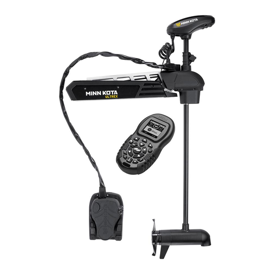
MINN KOTA ULTREX Installation Instructions Manual
Bow-mount trolling motor
Hide thumbs
Also See for ULTREX:
- Installation instructions manual (76 pages) ,
- Owner's manual (13 pages) ,
- Manual (13 pages)
Table of Contents
Advertisement
Quick Links
Advertisement
Table of Contents

Related Manuals for MINN KOTA ULTREX


Summary of Contents for MINN KOTA ULTREX
- Page 1 ULTREX™ BOW-MOUNT TROLLING MOTOR Installation Instructions...
-
Page 2: Motor Information
Thank you for choosing Minn Kota. We believe that you should spend more time fishing and less time positioning your boat. That’s why we build the smartest, toughest, most intuitive trolling motors on the water. Every aspect of a Minn Kota trolling motor is thought out and rethought until it’s good enough to bear our name. -
Page 3: Safety Considerations
WARNING You are responsible for the safe and prudent operation of your vessel. We have designed your Minn Kota product to be an accurate and reliable tool that will enhance boat operation and improve your ability to catch fish. This product does not relieve you from the responsibility for safe operation of your boat. -
Page 4: Know Your Boat
KNOW YOUR BOAT Starboard Starboard Port Port Inboard Inboard Outboard Outboard Keel Keel Port Port Starboard Starboard Gunwale Gunwale Transom Transom Stern Stern Gunwale Gunwale Stern Stern Hull Hull 4 | minnkotamotors.com ©2023 Johnson Outdoors Marine Electronics, Inc. -
Page 5: Installation
INSTALLING THE ULTREX Your new Ultrex comes with everything you’ll need to directly install it to the boat. This motor can be directly mounted to the boat or coupled with a Minn Kota quick release bracket for ease of mounting and removal. For installation with a quick release bracket, refer to the installation instructions provided with the bracket. - Page 6 ASSEMBLY OF STEERING MODULE TO MOUNT MOUNTING CONSIDERATIONS It is recommended that the motor be mounted as close to the keel or centerline of the boat as possible. Make sure the area under the mounting location is clear to drill holes View accessories and install nuts and washers.
- Page 7 INSTALLING THE MOUNT Reinstall the 5/16" Allen Screw and Lock Washer Allen Screw with Allen Screw with and tighten to 18 to 20 ft-lbs with a Torque Wrench. Lock Washer Lock Washer The 5/16" Allen Screw must be tightened when NOTICE: installed and periodically re-tightened to 18 to 20 ft-lbs.
- Page 8 INSTALLING THE MOUNT The Mount can be installed on either the Port Port Starboard or Starboard side of the boat based on personal preference. Test the placement of the Hold-Down Strap to be sure it can hold the Mount as placed. The placement of the buckle on the Hold-Down Strap either inboard or outboard is based on personal preference.
- Page 9 Once the Mount is in position, determine which bolt Pattern 1 Pattern 1 pattern to use. The bolt pattern selected will depend on the deck space available on your boat. Minn Kota requires the use of all six mounting holes. Pattern Pattern Mark all six mounting holes.
- Page 10 INSTALLING THE GAS SPRING Installing the Gas Spring Use the Pull Grip and Cable to disengage the Latch Pull Grip Pull Grip Bar on the Mount. Mount Mount and Cable and Cable With the help of a second person, loosen the Depth Collar and position the motor halfway between the stowed and deployed position so that the Lower Unit rests on the Motor Ramp.
- Page 11 Indexing the Motor It is recommended to have the Pedal Control Sleeve Assembly pointing inboard. Your Ultrex motor comes from the factory designed to be installed on the port side of the bow. If the Pedal Control Sleeve Assembly points outboard, please see the section "Rotate the Pedal Control Sleeve Assembly for a Starboard Mount."...
- Page 12 INDEXING THE MOTOR Remove the Connector Cover from the Wrap Drum Flat Flat Cover using a 1/8” Flat Screwdriver to release it. Screwdriver Screwdriver Release it by pressing the flat part of the screwdriver in the slot closest to the center of the Connector Cover and prying upwards.
- Page 13 INDEXING THE MOTOR The Cable Tension Screw that holds tension on the Steering Cables is located under the base of the Toe Toe End of Toe End of End of the Foot Pedal. This screw can be loosened Foot Pedal Foot Pedal just enough so that the Steering Cables can be pinched together between the Cable Anchor and...
- Page 14 INDEXING THE MOTOR While holding the Wrap Drum just above the Cable Steering Steering Steering Motor Steering Motor Gear, and maintaining tension on the Steering Connection Wire Connection Wire Module Module Wrap Drum Wrap Drum Cables, carefully rotate the Wrap Drum right or left until the top of the Foot Pedal is parallel with the deck of the boat.
- Page 15 INDEXING THE MOTOR Reconfirm that the Steering Cables are tight and Wrap Drum Wrap Drum then carefully thread the Steering Motor Connection Cover Cover Steering Motor Steering Motor Wire through the top of the Wrap Drum Cover. The Connection Wire Connection Wire male plug comes from the Cable Anchor through the opening at the bottom of the Wrap Drum Cover.
- Page 16 Rotate the Pedal Control Sleeve Assembly for a Starboard Mount By default, the Pedal Control Sleeve Assembly is factory-set so that when your Ultrex is installed on the port side of your boat, the Pedal Control Sleeve Assembly points inboard. Should you choose to install your Ultrex on the Starboard side of your boat, it is recommended that the default position of the Pedal Control Sleeve Assembly be rotated to point inboard.
- Page 17 ROTATE THE PEDAL CONTROL SLEEVE ASSEMBLY FOR A STARBOARD MOUNT Remove the Connector Cover from the Wrap Drum Flat Flat Cover using a 1/8” Flat Screwdriver to release it. Screwdriver Screwdriver Release it by pressing the flat part of the Screwdriver in the slot closest to the center of the Connector Cover and prying upwards.
- Page 18 ROTATE THE PEDAL CONTROL SLEEVE ASSEMBLY FOR A STARBOARD MOUNT The Cable Anchor functions to hold the Steering Cables in place. The cables run from the Cable Anchor and wrap around the Wrap Drum. The Cable Anchor is secured to the Steering Module with two Screws.
- Page 19 ROTATE THE PEDAL CONTROL SLEEVE ASSEMBLY FOR A STARBOARD MOUNT Secure the Cable Anchor to the inboard side of the Steering Steering Steering Module by loosely securing the screws in Module Module Screws Screws place using a #2 Phillips Screwdriver. Once the Cable Anchor is secured, finish prying the Wrap Drum straight up, off of the Cable Gear until Cable...
- Page 20 ROTATE THE PEDAL CONTROL SLEEVE ASSEMBLY FOR A STARBOARD MOUNT Re-tighten the two screws that fasten the Cable Steering Steering Anchor to the top of the Steering Module using a #2 Module Module Screws Screws Phillips Screwdriver. Tighten to 25 in-lbs. Cable Cable Anchor...
-
Page 21: Placing The Bow-Mount Stabilizer
The Bow-Mount Stabilizer Bracket can be installed on the left or right side of the Steering Module. When mounting the bracket onto the Ultrex, the two Nylock Nuts (Item #16) are discarded because the bolts are secured directly into the Steering Module. - Page 22 PLACING THE BOW-MOUNT STABILIZER ITEM(S) NEEDED #17 x 2 #18 x 2 Determine the desired orientation of the Stabilizer Steering Steering Bracket and attach it to the bottom of the Steering Module Module Module. Place a Lock Washer (Item #18) on each of Lock Washer Lock Washer and Cap Screw...
-
Page 23: Mounting The Foot Pedal
MOUNTING THE FOOT PEDAL Replace the Bottom Bumper on the Aluminum Rod, Stabilizer Bracket Stabilizer Bracket opposite from the threads. Thread the Aluminum Rod into the Stabilizer Bracket Jam Nut Jam Nut with the Bottom Bumper towards the boat deck. Adjust the Aluminum Rod up or down in the Stabilizer Bracket so that the Bottom Bumper just Aluminum Rod... - Page 24 Feature & Cable Identification The Ultrex is pre-installed with Advanced GPS Navigation - including the ability to connect via Ethernet to a Humminbird unit. It is also installed with sonar, either Dual Spectrum CHIRP or Built-in MEGA Down Imaging. Dual Spectrum CHIRP and Built-in MEGA Down Imaging will be installed in combination with Advanced GPS Navigation.
-
Page 25: Identifying Connectors
IDENTIFYING CONNECTORS Identifying Connectors TWO Connectors Every Ultrex will have TWO connectors present below the Control Control Control Advanced GPS Advanced GPS Head Head Head. The trolling motor will be equipped with: Ethernet Ethernet Connector Connector Advanced GPS Navigation & Dual Spectrum CHIRP or Built-in... - Page 26 FEATURE & CABLE MANAGEMENT Feature & Cable Management DUAL SPECTRUM CHIRP Your trolling motor may be pre-installed with a transducer system Dual Spectrum CHIRP featuring Humminbird’s Dual Spectrum CHIRP. CHIRP stands for “Compressed High Intensity Radar Pulse”. Dual Spectrum CHIRP is a 2D sonar transducer with a temperature sensor that is integrated into the lower unit of the trolling motor.
- Page 27 DUAL SPECTRUM CHIRP The integrated design of the Dual Spectrum CHIRP transducer protects it in the lower unit of the trolling motor from underwater hazards and prevents tangles and damage to the transducer cables. In certain situations, air bubbles may adhere to the surface of the Dual Spectrum CHIRP transducer and affect the performance.
- Page 28 DUAL SPECTRUM CHIRP All Dual Spectrum CHIRP Ultrex motors are equipped with an internal bonding wire. Incorrect rigging will cause sonar interference and can damage your trolling motor, electronics, and other boat accessories. To minimize trolling motor interference, ensure that the fish finder and trolling motor are powered by separate batteries.
- Page 29 DUAL SPECTRUM CHIRP If installing directly to a Solix or Apex, the connection Fourteen Pin Fourteen Pin will be flat on the back of the fish finder display. Connector Connector Align the pins on the Accessory Cable with the Solix or Apex Solix or Apex receptacle on the fish finder.
- Page 30 DUAL SPECTRUM CHIRP ITEM(S) NEEDED #24 or 25 x 1 If installing directly to a Helix Adapter Cable, align Fourteen Pin Fourteen Pin Receptacle Receptacle the pins on the accessory cable or extension cable Connector Connector with the receptacle on the Helix Adapter Cable (Item #24 or 25).
- Page 31 BUILT-IN MEGA DOWN IMAGING BUILT-IN MEGA DOWN IMAGING Built-in MEGA Down Imaging delivers nearly 3X the output of standard Side Imaging®, and takes fishfinding into the megahertz frequency for the very first time. It uses a razor-thin, high-frequency beam to create picture-like images of structure, vegetation and fish. With Humminbird MEGA imaging sonar built right into the trolling motor, you now have a crystal clear view of what’s directly beneath the boat, without having to manage all of the cables that come with external transducers.
- Page 32 BUILT-IN MEGA DOWN IMAGING CAUTION Failure to follow the recommended wire routing for installed features, if equipped, may cause damage to the product and void your product warranty. Route cables away from pinch points or other areas that may cause them to bend in sharp angles. Routing the cables in any way other than directed may cause damage to the cables by being pinched or severed.
- Page 33 BUILT-IN MEGA DOWN IMAGING If installing directly to a Solix or Apex, the Fourteen Pin Connector Fourteen Pin Connector connection will be flat on the back of the fish finder display. Built-in MEGA Down Built-in MEGA Down Solix or Apex Solix or Apex Align the pins on the Accessory Cable with the Imaging Accessory Cable...
- Page 34 BUILT-IN MEGA DOWN IMAGING ITEM(S) NEEDED #24 or 25 x 1 If installing directly to a Helix Adapter Cable, align Receptacle Receptacle Fourteen Pin Fourteen Pin the pins on the accessory cable or extension cable Connector Connector with the receptacle on the Helix Adapter Cable (Item #24 or 25).
- Page 35 ADVANCED GPS NAVIGATION Your Minn Kota trolling motor and Humminbird fish finder communicate with each other to change the way you fish. Advanced GPS Navigation offers a large array of features including controlling speed, steering, Spot-Lock, and the ability to record and retrace tracks on the water, all at your fingertips.
- Page 36 Cord Sonar Sonar Cable Cable NOTICE: Ultrex trolling motors with Advanced GPS Mount Mount Navigation will also be equipped with Sonar. Sonar is pre-installed from the factory and may be either Dual Spectrum CHIRP or Built-in MEGA Down Imaging. With...
- Page 37 ADVANCED GPS NAVIGATION ITEM(S) NEEDED #8 x 1 Take the Ethernet Cable (Item #8) and identify the Receptacle Receptacle Eight Pin Eight Pin Receptacle on either end. It will be keyed to fit with Connector Connector the Eight Pin Advanced GPS Ethernet Connector below the Control Head.
- Page 38 ADVANCED GPS NAVIGATION Minn Kota recommends routing the NOTICE: Advanced GPS Advanced GPS Ethernet Ethernet Ethernet Cable parallel to the Coil Cord when Control Control Connector Connector making the Ethernet connection. The cable will Head Head be installed from the Mount to the Control Head...
- Page 39 Cable Cable Cable to secure the connection. Helix Adapter Cable Helix Adapter Cable NOTICE: Minn Kota provides one Helix Adapter Cable (AS EC QDE - Ethernet Adapter Cable - 720074-1) with every trolling motor equipped with Advanced GPS Navigation. Ethernet...
- Page 40 Do not over-tighten the clips as it may damage the wires. NOTICE: If replacement Clips (Part No. 2290844) are needed, they can be ordered online at the Minn Kota Parts Ordering Portal at minnkotomotors.com. 40 | minnkotamotors.com ©2023 Johnson Outdoors Marine Electronics, Inc.
- Page 41 SECURING ACCESSORY CABLES The Ultrex comes from the factory with the Sonar Advanced GPS Advanced GPS Cable secured to the Coil Cord with five Clips. The Ethernet Connector Ethernet Connector Clips are evenly spaced down the Coil Cord from the Control Head to the Mount.
- Page 42 INSTALLING THE PROP Installing the Prop CAUTION Prop Prop Drive Drive Washer Washer Disconnect the motor from the battery before Prop Prop beginning any prop work or maintenance. While holding the Shipping Spacer with a pliers or vise grip, remove the Prop Nut, Red Shipping Shipping Shipping Washer, Prop Washer and Spacer, being careful...
- Page 43 INSTALLING THE PROP Holding the end of the Armature Shaft with a Flat Blade Screwdriver, tighten the Prop Nut with a 9/16" Box End or Open End Wrench. Prop Nut Prop Nut Tighten the Prop Nut 1/4 turn past snug to Prop Washer Prop Washer 25-35 in-lbs.
-
Page 44: Battery & Wiring Installation
CAUTION These guidelines apply to general rigging to support your Minn Kota motor. Powering multiple motors or additional electrical devices from the same power circuit may impact the recommended conductor gauge and circuit breaker size. If you are using wire longer than that provided with your unit, follow the conductor gauge and circuit breaker sizing table below. -
Page 45: Selecting The Correct Batteries
Using Alternator Chargers Your Minn Kota trolling motor may be designed with an internal bonding wire to reduce sonar interference. Most alternator charging systems do not account for this bonding wire, and connect the negative posts of the trolling motor batteries to the negative posts of the crank/ starting battery. - Page 46 CONNECTING THE BATTERIES IN SERIES The negative (-) connection must be connected to the negative terminal of the same battery that the trolling motor negative lead connects to. In the diagrams below this battery is labeled “Low Side” Battery. Connecting to any other trolling motor battery will input positive voltage into the “ground”...
- Page 47 Keep leadwire wing nut connections tight and solid to battery terminals. • Locate battery in a ventilated compartment. This completes the installation of your Ultrex. A complete Owner’s Manual can be downloaded at minnkotamotors.com. ©2023 Johnson Outdoors Marine Electronics, Inc.
-
Page 48: Recommended Accessories
Stop buying new batteries and start taking care of the ones you’ve got. Many chargers can actually damage your battery over time – creating shorter run times and shorter overall life. Digitally controlled Minn Kota chargers are designed to provide the fastest charge that protect and extend battery life. MK212PCL...
Need help?
Do you have a question about the ULTREX and is the answer not in the manual?
Questions and answers
Does the Ultrex 45 inch shaft require the bow mount stabilizer
The Minn Kota Ultrex 45-inch shaft can be installed with a Bow-Mount Stabilizer Bracket. The manual provides instructions for mounting the stabilizer bracket on either the left or right side of the steering module. However, it does not explicitly state that the stabilizer is required, only that it can be installed.
This answer is automatically generated