Table of Contents
Advertisement
Quick Links
A l l t e s t I n s t r u me n t s , I n c .
5 0 0 C e n t r a l A v e .
F a r mi n g d a l e , N J 0 7 7 2 7
P : ( 7 3 2 ) 9 1 9 - 3 3 3 9
F : ( 7 3 2 ) 9 1 9 - 3 3 3 2
a l l t e s t . n e t
s s a l e s @ a l l t e s t . n e t
T h e t e s t & me a s u r e me n t
e q u i p me n t y o u n e e d a t
t h e p r i c e y o u w a n t .
A l l t e s t c a r r i e s t h e w o r l d ' s l a r g e s t s e l e c t i o n o f
u s e d / r e f u r b i s h e d b e n c h t o p t e s t & me a s u r e me n t
e q u i p me n t a t 5 0 % t h e p r i c e o f n e w .
O O u r e q u i p me n t i s g u a r a n t e e d w o r k i n g , w a r r a n t i e d , a n d
a v a i l a b l e w i t h c e r t i f i e d c a l i b r a t i o n f r o m o u r i n - h o u s e s t a f f
o f t e c h n i c i a n s a n d e n g i n e e r s .
• 1 0 + f u l l t i me t e c h n i c i a n s w i t h o v e r 1 5 0 y e a r s o f
s p e c i a l i z a t i o n
• 9 0 d a y w a r r a n t y & 5 d a y r i g h t o f r e t u r n o n a l l
e q u i p me n t
• • 1 - 3 y e a r w a r r a n t i e s f o r n e w a n d
p r e mi u m- r e f u r b i s h e d e q u i p me n t
• E v e r y u n i t t e s t e d t o O E M s p e c i f i c a t i o n s
• S a t i s f a c t i o n g u a r a n t e e d
Y o u h a v e p l a n s , w e w i l l h e l p y o u a c h i e v e t h e m.
A n y p r o j e c t . A n y b u d g e t .
t
G e t a q u o t e t o d a y !
C C a l l ( 7 3 2 ) 9 1 9 - 3 3 3 9 o r e ma i l s a l e s @a l l t e s t . n e t .
Advertisement
Table of Contents

Related Manuals for Agilent Technologies 86060A


Summary of Contents for Agilent Technologies 86060A
- Page 1 T h e t e s t & me a s u r e me n t e q u i p me n t y o u n e e d a t t h e p r i c e y o u w a n t . A l l t e s t I n s t r u me n t s , I n c .
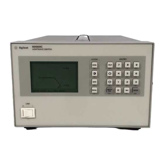
- Page 2 Agilent 86060C-Series Lightwave Switches User’s Guide...
- Page 3 ❍ © Copyright material and workmanship for gies shall not be liable for any The OFF symbols Agilent Technologies 2000 a period of one year from date direct, indirect, special, inci- are used to mark the All Rights Reserved. Repro- of shipment.
- Page 4 General Safety Considerations General Safety Considerations This product has been designed and tested in accordance with IEC Publica- tion 61010-1, Safety Requirements for Electrical Equipment for Measurement, Control and Laboratory Use, and has been supplied in a safe condition. The instruction documentation contains information and warnings that must be followed by the user to ensure safe operation and to maintain the product in a safe condition.
- Page 5 General Safety Considerations W A R N I N G For continued protection against fire hazard, replace line fuse only with same type and ratings, (type T 0.315A/250V for 100/120V operation and 0.16A/250V for 220/240V operation). The use of other fuses or materials is prohibited.
-
Page 6: Table Of Contents
Channels, Options, and Accessories 1-3 Specifications and Regulatory Information 1-7 Cleaning Connections for Accurate Measurements 1-12 Returning the Instrument for Service 1-22 Agilent Technologies Service Offices 1-25 2 Installing Step 1. Inspect the shipment 2-3 Step 2. Check the fuse 2-4 Step 3. -
Page 8: General Information
Channels, Options, and Accessories 1-3 Specifications and Regulatory Information 1-7 Cleaning Connections for Accurate Measurements 1-12 Returning the Instrument for Service 1-22 Agilent Technologies Service Offices 1-25 General Information... - Page 9 General Information General Information General Information The Agilent 86060C-series lightwave switches cover a broad range of switch- ing capacity and provide for accurate and repeatable measurements. Configur- ing the switch is easy because the signal routing is shown graphically on the display.
-
Page 10: Channels, Options, And Accessories
Other switch configurations, such as non-blocking matrices are avail- able as special orders. Serial numbers Agilent Technologies makes frequent improvements to its products to enhance their performance, usability, or reliability, and to control costs. Agi- lent Technologies service personnel have access to complete records of design... - Page 11 General Information Channels, Options, and Accessories Whenever you contact Agilent Technologies about your lightwave switch, have the complete serial number available to ensure obtaining the most complete and accurate information possible. A serial-number label is attached to the rear of the lightwave switch. It con- tains the serial number and the options installed in the lightwave switch.
- Page 12 General Information Channels, Options, and Accessories Table 1-2. Options (1 of 2) Option Description Number of Input Channels (select one): Option 001 Single input channel Option 002 Two input channels Wavelength and Fiber Type (select one): µ Option 109 1280–1650 nm, 9/125 m single-mode fiber µ...
- Page 13 General Information Channels, Options, and Accessories Table 1-2. Options (2 of 2) Option Description Optional Accessories Option ABJ User’s manual in Japanese Option UK6 Commercial calibration certificate with test data Option 1CM Rack-mount flange kit Option 1CN Front handle kit Option 1CP Rack mount flange kit with handles Table 1-3.
-
Page 14: Specifications And Regulatory Information
To maintain specifications, periodic recalibrations are necessary. We recommend that the Agilent 86060C-series switches be cali- brated at an Agilent Technologies service facility every 24 months. C A U T I O N Improper connector care, cleaning, or use of mismatched cable connectors can invalidate the published specifications and damage connectors. - Page 15 General Information Specifications and Regulatory Information Table 1-4. Optical Interface Specifications and Characteristics Insertion Loss Single-mode switches 1.0 dB (0.7 dB) Multi-mode switches 0.8 dB (0.6 dB) ±0.03 dB (±0.025) Insertion Loss Stability Repeatability Sequential switching ±0.008 dB (±0.005) Random switching ±0.025 dB (±0.01) Optical Return Loss Single-mode...
- Page 16 General Information Specifications and Regulatory Information Table 1-5. Switching Time Sample (msec) Starting Channel to Plus Additional Maximum Switch Size Switch Adjacent Channels Time/Channel Switching Time 1×4 Agilent 86060C, HP 86061C 1×8 Agilent 86060C, HP 86061C 1×56 HP 86062C 1×100 HP 86062C a.
- Page 17 HP 86062C a. All Agilent 86060C-series lightwave switches must specify one of the following options, except when specifying Option 3xx. b. Unlike most Agilent Technologies lightwave instruments, connector types are not interchangeable. c. Other connector types are available upon request.
- Page 18 General Information Specifications and Regulatory Information 1-11...
-
Page 19: Cleaning Connections For Accurate Measurements
Connectors also vary in the polish, curve, and concentricity of the core within the cladding. Mating one style of cable to another requires an adapter. Agilent Technologies offers adapters for most instruments to allow testing with many different cables. - Page 20 General Information Cleaning Connections for Accurate Measurements tions take repeatability uncertainty into account? • Will a connector degrade the return loss too much, or will a fusion splice be re- quired? For example, many DFB lasers cannot operate with reflections from connectors.
- Page 21 0.2 µm. This process, plus the keyed axis, allows very precise core-to-core alignments. This connector is found on most Agilent Technologies lightwave instruments. 1-14...
- Page 22 General Information Cleaning Connections for Accurate Measurements The soft core, while allowing precise centering, is also the chief liability of the connector. The soft material is easily damaged. Care must be taken to mini- mize excessive scratching and wear. While minor wear is not a problem if the glass face is not affected, scratches or grit can cause the glass fiber to move out of alignment.
- Page 23 General Information Cleaning Connections for Accurate Measurements Use the following guidelines to achieve the best possible performance when making measurements on a fiber-optic system: • Never use metal or sharp objects to clean a connector and never scrape the connector. •...
- Page 24 General Information Cleaning Connections for Accurate Measurements Figure 1-6. Damage from improper cleaning. While these often work well on first insertion, they are great dirt magnets. The oil or gel grabs and holds grit that is then ground into the end of the fiber. Also, some early gels were designed for use with the FC, non-contacting con- nectors, using small glass spheres.
- Page 25 General Information Cleaning Connections for Accurate Measurements • Keep connectors covered when not in use. • Use fusion splices on the more permanent critical nodes. Choose the best con- nector possible. Replace connecting cables regularly. Frequently measure the return loss of the connector to check for degradation, and clean every connec- tor, every time.
- Page 26 Cleaning Connectors The procedures in this section provide the proper steps for cleaning fiber- optic cables and Agilent Technologies universal adapters. The initial cleaning, using the alcohol as a solvent, gently removes any grit and oil. If a caked-on layer of material is still present, (this can happen if the beryllium-copper sides of the ferrule retainer get scraped and deposited on the end of the fiber during insertion of the cable), a second cleaning should be performed.
- Page 27 General Information Cleaning Connections for Accurate Measurements Table 1-8. Dust Caps Provided with Lightwave Instruments Item Agilent Part Number Laser shutter cap 08145-64521 FC/PC dust cap 08154-44102 Biconic dust cap 08154-44105 DIN dust cap 5040-9364 HMS10/dust cap 5040-9361 ST dust cap 5040-9366 To clean a non-lensed connector C A U T I O N...
- Page 28 To clean an adapter The fiber-optic input and output connectors on many Agilent Technologies instruments employ a universal adapter such as those shown in the following picture. These adapters allow you to connect the instrument to different types of fiber-optic cables.
-
Page 29: Returning The Instrument For Service
Technologies Service Offices” on page 1-25 for a list of service offices. Agilent Technologies Instrument Support Center ... (800) 403-0801 If the instrument is still under warranty or is covered by an Agilent Technolo- gies maintenance contract, it will be repaired under the terms of the warranty or contract (the warranty is at the front of this manual). - Page 30 They may also cause instrument damage by generating static electricity. 3 Pack the instrument in the original shipping containers. Original materials are available through any Agilent Technologies office. Or, use the following guidelines: • Wrap the instrument in antistatic plastic to reduce the possibility of damage caused by electrostatic discharge.
- Page 31 General Information Returning the Instrument for Service Sealed Air Corporation (Commerce, California 90001). Air Cap looks like a plastic sheet filled with air bubbles. Use the pink (antistatic) Air Cap™ to reduce static electricity. Wrapping the instrument several times in this ma- terial will protect the instrument and prevent it from moving in the carton.
-
Page 32: Agilent Technologies Service Offices
General Information Agilent Technologies Service Offices Agilent Technologies Service Offices Before returning an instrument for service, call the Agilent Technologies Instrument Support Center at (800) 403-0801, visit the Test and Measurement Web Sites by Country page at http://www.tm.agilent.com/tmo/country/English/ index.html, or call one of the numbers listed below. -
Page 34: Installing
Step 1. Inspect the shipment 2-3 Step 2. Check the fuse 2-4 Step 3. Connect the line-power cable 2-5 Step 4. Turn on the lightwave switch 2-7 Step 5. Performing an operational check 2-8 If The Operational Check Fails 2-10 Installing... - Page 35 Installing Installing Installing W A R N I N G Before installing the lightwave switch, See “General Safety Considerations” on page iii of this manual. C A U T I O N OPTION 3XX INSTRUMENTS: To avoid damage, handle the pigtail fiber with care.
-
Page 36: Step 1. Inspect The Shipment
Inspect all shipping containers. If your shipment is damaged or incomplete, save the packing materials and notify both the shipping carrier and the nearest Agilent Technologies service office. Agilent Technologies will arrange for repair or replacement of damaged or incomplete shipments without waiting for a settlement from the transportation company. -
Page 37: Step 2. Check The Fuse
Installing Step 2. Check the fuse Step 2. Check the fuse 1 Locate the line-input connector on the instrument’s rear panel. 2 Disconnect the line-power cable if it is connected. 3 Use a small flat-blade screwdriver to open the pull-out line fuse drawer. W A R N I N G For continued protection against fire hazard, replace line fuse only with same type and ratings (2A/250V). -
Page 38: Step 3. Connect The Line-Power Cable
Installing Step 3. Connect the line-power cable Step 3. Connect the line-power cable 1 Verify that the line power meets the requirements shown in the following table. Table 2-1. Agilent 86060C-Series Power Requirements Characteristic Requirement Input Voltage within range 90 to 254 Vac Frequency within range 47 to 63 Hz Power... -
Page 39: Power Cords
Straight MITI 90/230 Dark Gray Japan 8120-4754 90° 90/230 * Part number shown for plug is the industry identifier for the plug only. Number shown for cable is the Agilent Technologies part number for the complete cable including the plug. -
Page 40: Step 4. Turn On The Lightwave Switch
Installing Step 4. Turn on the lightwave switch Step 4. Turn on the lightwave switch 1 Turn the lightwave switch on by pressing the line switch. The liquid-crystal display (LCD) displays the message: Initializing Screen Saver A screen-saver has been built in to the switch to prolong the lifetime of the backlit LCD. The screen-saver turns off the LCD backlighting after 10 minutes elapses without a front-panel key being pressed. -
Page 41: Step 5. Performing An Operational Check
Installing Step 5. Performing an operational check Step 5. Performing an operational check C A U T I O N Improper connector care, cleaning, or use of mismatched cable connectors can invalidate the published specifications and damage connectors. Clean all cables before applying to any connector. - Page 42 Installing Step 5. Performing an operational check Many other possibilities exist. The basic requirements are an appropriate lightwave source and a compatible lightwave receiver. Refer to the manuals provided with your lightwave test equipment for information on how to per- form an insertion loss test.
-
Page 43: If The Operational Check Fails
A few minutes spent performing some simple checks may save waiting for your instrument to be repaired. Before calling Agilent Technologies or returning the unit for ser- vice, please make the following checks:... -
Page 44: Using The Switch
Front-Panel Features 3-3 Rear-Panel Features 3-5 Changing Switch Position 3-6 Adjusting Display Contrast 3-7 Saving Switch States 3-7 Using the Switch... - Page 45 Using the Switch Using the Switch Using the Switch This chapter describes the front and rear-panel features. It also provides step- by-step procedures for configuring the lightwave switch. Position the light- wave switch according to the enclosure protection provide. This instrument does not protect against the ingress of water.
-
Page 46: Front-Panel Features
Using the Switch Front-Panel Features Front-Panel Features Figure 3-1. The Agilent 86060C-series front-panel functional area Screen Saver A screen-saver has been built in to the switch to prolong the lifetime of the backlit LCD. The screen-saver turns off the LCD backlighting after 10 minutes elapses without a front-panel key being pressed. - Page 47 Using the Switch Front-Panel Features LOCAL key Press this key to display the GPIB address of the lightwave switch. You can also change the address using the numeric keypad. If a computer has placed the instrument in remote control, is this key to reenable front-panel control. SAVE &...
-
Page 48: Rear-Panel Features
Using the Switch Rear-Panel Features Rear-Panel Features Figure 3-2. The Agilent 86060C-series rear-panel functional area Optical The number of optical connectors depends on the Agilent 86060C-series connector(s) switch. The connectors are grouped as Port A and Port B. GPIB connector Provides for remote control of the lightwave switch via the GPIB interface bus. -
Page 49: Changing Switch Position
Using the Switch Changing Switch Position Changing Switch Position To set single port A switches The 1 × N switch has a single Port A channel and multiple Port B channels. 1 To select a Port B channel, press: SWITCH PORT The Port B channels are shown in inverse video and the prompt, Port B active, appears at the bottom of the display. -
Page 50: Adjusting Display Contrast
Using the Switch Adjusting Display Contrast Adjusting Display Contrast To adjust the contrast of the display, press the key. Use the arrow keys to select the desired contrast, then press ENTER. Saving Switch States To save a state To save the currently displayed switch state in one of the ten internal storage registers, press SAVE, and then press one of the numeric keys (0–9). -
Page 52: Programming
General Information 4-3 Programming over GPIB 4-6 Programming over RS-232 4-8 Common Commands 4-11 Standard SCPI Commands 4-22 Instrument Specific Commands 4-26 Error Messages 4-30 Programming Examples 4-31 Programming... - Page 53 Programming Programming Programming The programming instructions in this manual conform to the IEEE 488.2 Stan- dard Digital Interface for Programmable Instrumentation and to the Standard Commands for Programmable Instruments (SCPI). The programming instruc- tions provide the means of remote control. Where to begin .
-
Page 54: General Information
Programming General Information General Information This instrument has three types of commands: • Common commands • Standard SCPI commands • Instrument specific commands Common The common commands are the commands defined by IEEE 488.2. These commands commands control some functions that are common to all IEEE 488.2 instru- ments. - Page 55 Programming General Information switch layers, the switch layers are referred to by the word LAYER in the ROUTE:LAYER:CHANNEL command. The numeric value at the end of the mnemonic LAYER selects the switch block to which the ROUTE:LAYER:CHANNEL command should be applied. For example, in the following program statement, the command is applied to switch layer 2 of the instrument.
- Page 56 Programming General Information Command headers immediately followed by a question mark (?) are queries. Query commands are used to find out information regarding the instrument’s current state. After receiving a query, the instrument interrogates the requested function and places the answer in its output queue. The answer remains in the output queue until it is read or another command is issued.
-
Page 57: Programming Over Gpib
Programming Programming over GPIB Programming over GPIB This section describes the GPIB interface functions and some general con- cepts. In general, these functions are defined by IEEE 488.2. They deal with general interface management issues, as well as messages which can be sent as interface commands. - Page 58 Programming Programming over GPIB Interface select Each interface card has a unique interface select code. This code is used by code (selects the controller to direct commands and communications to the proper inter- interface) face. The default is typically "7" for GPIB controllers. Instrument Each instrument on an GPIB must have a unique instrument address between address (selects...
-
Page 59: Programming Over
Programming Programming over RS-232 Programming over RS-232 This section describes the interface functions and some general concepts of the RS-232 interface. The RS-232 interface on this instrument is Hewlett- Packard’s implementation of EIA Recommended Standard RS-232, "Interface Between Data Terminal Equipment and Data Communications Equipment Employing Serial Binary Data Interchange."... - Page 60 Programming Programming over RS-232 3-wire interface The switch uses a 3-wire RS-232 interface. It provides a simple connection between devices because you can ignore hardware handshake requirements. The switch uses the following connections on its RS-232 interface for 3-wire communication: Switch Computer SGND (Signal Ground)
- Page 61 Programming Programming over RS-232 Information is stored in bytes (8 bits at a time) in the switch. Data can be sent and received just as it is stored, without the need to convert the data. Communicating Each RS-232 interface card has its own interface select code. This code is over the RS-232 used by the controller to direct commands and communications to the proper interface...
-
Page 62: Common Commands
Programming Common Commands Common Commands The following commands are required by the IEEE 488.2–1987 standard. *CLS (Clear Status) The *CLS (clear status) common command clears all the event registers sum- marized in the Status Byte register. With the exception of the output queue, all queues that are summarized in the Status Byte Register are emptied. - Page 63 Programming *ESE (Event Status Enable) The Standard Event Status Enable Register is cleared at power-on. The *RST and *CLS commands do not change the register. The *ESE query returns the value of the Standard Event Status Enable Regis- ter. Usage: GPIB only Command Syntax: *ESE <mask>...
- Page 64 Programming *ESR (Event Status Register) Table 4-1. Standard Event Status Enable Register (High–Enables the ERS bit) Bit Weight Enables NOT USED OPC – Operation Complete *ESR (Event Status Register) The *ESR query returns the value of the Standard Event Status Register. When you read the Event Status Register, the value returned is the total of the bit weights of all of the bits that are set to one at the time you read the byte.
- Page 65 Programming *IDN (Identification Number) Table 4-2. Standard Event Status Register Bit Weight Condition EXE – Execution Error NOT USED QYE – Query Error NOT USED OPC – Operation Complete *IDN (Identification Number) The *IDN query returns a string value which identifies the instrument type and firmware version.
- Page 66 Programming *OPC (Operation Complete) *OPC (Operation Complete) The *OPC command sets the operation complete bit in the Standard Event Status Register when all pending device operations have finished. The *OPC query places an ASCII "1" in the output queue when all pending device operations have finished.
- Page 67 Programming *RST (Reset) Command Syntax: *RCL <value> Where: <value> ::= 0 to 9 (integer–NR1 format) Example: OUTPUT 711;"*RCL 3" *RST (Reset) The *RST command returns the switch to its power-up condition. For all lay- ers, each port is set to its OFF position or channel 1. Usage: GPIB and RS-232 Command Syntax: *RST...
- Page 68 Programming *SRE (Service Request Enable) *SRE (Service Request Enable) The *SRE command sets the bits in the Service Request Enable Register. The Service Request Enable Register contains a mask value for the bits to be enabled in the Status Byte Register. A bit set to one (1) in the Service Request Enable Register enables the corresponding bit in the Status Byte Register.
- Page 69 Programming *SRE (Service Request Enable) Table 4-3. Service Request Enable Register Service Request Enable Register (High–Enables the SRE bit) Bit Weight Enables Not Used MSS – Master Summary Status ESB – Event Status Bit MAV – Message Available Not Used Not Used Not Used OPP –...
- Page 70 Programming *STB (Status Byte) *STB (Status Byte) The *STB query returns the current value of the instrument’s status byte. The MSS (Master Summary Status) bit 6 indicates whether or not the device has at least one reason for requesting service. When you read the Status Byte Register, the value returned is the total of the bit weights of all the bits set to one (1) at the time you read the byte.
- Page 71 Programming *TST (Test) Table 4-4. Status Byte Register Bit Weight Condition Not Used MSS – Master Summary Status ESB – Event Status Bit MAV – Message Available Not Used Not Used Not Used OPP – Operation Pending *TST (Test) The *TST query performs a self-test on the instrument. The result of the test is placed in the output queue.
- Page 72 Programming *WAI (Wait) *WAI (Wait) The *WAI command prevents the instrument from executing any further com- mands until the current command has finished executing. All pending opera- tions are completed during the wait period. NOTE The *WAI command can be used to ensure all switch movement operations have com- pleted before continuing the program.
-
Page 73: Standard Scpi Commands
Programming Standard SCPI Commands Standard SCPI Commands :STATus:<node>:CONDition The :STATus:<node>:CONDition query returns the value for the condition register for the node. Condition registers have no function in this instrument, but the query is included for compatability with the SCPI standard. This query always returns the value 0. - Page 74 Programming :STATus:<node>[:EVENT] Command Syntax: :STATus:<node>:ENABle<value> Where: <node> = OPERation | QUEStionable <value> ::= 0 to 32767 (integer or floating point – NR1) Example: OUTPUT 711;":STATUS:QUESTIONABLE:ENABLE 1024" Query Syntax: :STATus:<node>:ENABle? Returned Format: <value> <node> = OPERation | QUEStionable Where: <value> ::= 0 to 32767 (integer – NR1) Example: OUTPUT 711;":STATUS:QUESTIONABLE:ENABLE?"...
- Page 75 Programming :STATus:PRESet :STATus:PRESet The :STATus:PRESet command presets the enable registers for all status nodes. Enable registers have no function in this instrument, but the command is included for compatability with the SCPI standard. Table 4-5 shows the value of each enable register. Usage: GPIB only Query Syntax:...
- Page 76 Programming :SYSTem:ERRor Where: <value> = an integer error code (NR1) <string> = text of error message Example: DIM Error$[50] OUTPUT 711;":SYSTEM:ERROR?" ENTER 711;Error$ PRINT Error$ 4-25...
-
Page 77: Instrument Specific Commands
Programming Instrument Specific Commands Instrument Specific Commands The following commands are specific to remote operation of the Agilent 86060C-series lightwave switches. CLOSE RS232 COM The CLOSE RS232 COM command disables remote operation of the instru- ment over the RS-232 interface and enables the front-panel keyboard. This command is the same as pressing the LOCAL key while in remote operation over the RS-232 interface. - Page 78 Programming [:ROUTe]:[LAYer]:CHANnel Example: com_port=9 OUTPUT com_port; "OPEN RS232 COM" [:ROUTe]:[LAYer]:CHANnel The [:ROUTe]:[LAYer]:CHANnel command configures the channel connec- tions. In the command syntax, the keyword “LAYer” refers to a switch layer. A switch layer is a switch matrix of “A” ports and “B” ports. Normal lightwave switches have only one layer installed.
- Page 79 Programming :SYSTem:CONFig Example: OUTPUT 711;":ROUTE:LAYER2:CHANNEL A2,B78" Connects A2 to B78 on layer 2 Query Syntax: [:ROUTe]:[LAYer<layer>]:CHANnel? Where: <layer> a positive integer (NR1) Returned Format: A<channel>,B<channel> <channel> = a non-negative integer (NR1) Example: DIM Setting$ OUTPUT 711;":ROUTE:LAYER3:CHANNEL?" ENTER 711;Setting$ PRINT Setting$ :SYSTem:CONFig The :SYSTem:CONFig query returns the switch configuration of the instru- ment.
- Page 80 Programming :SYSTem:CONFig Example: DIM Config$ OUTPUT 711;":SYSTem:CONFIG?" ENTER 711;Config$ PRINT Config$ 4-29...
-
Page 81: Error Messages
Programming Error Messages Error Messages Table 4-6. Error Messages Error Number Description –105 GET not allowed –110 Command Header error –120 Numeric Data error –140 Character Data error –150 String Data error –170 Expression error –220 Parameter error –350 Too many errors –410 Query INTERRUPTED –420... -
Page 82: Programming Examples
Programming Programming Examples Programming Examples This section includes a number of programming examples to illustrate the use of remote commands in actual programs. These programming examples do not cover the full command set for the instrument. They are intended only as an introduction to the method of programming the instrument. - Page 83 Programming Programming Examples Example 1: Switch position using the *WAI command This program prompts the operator for the desired switch position and then moves the switch to this position. The switch error queue is then read and printed. The program shows how to use the *WAI command to ensure that the switch has settled to its new position.
- Page 84 Programming Programming Examples the form appropriate for the ROUTE:LAYER:CHANNEL GPIB command. For example, if A_position=1 and B_position=3, then Channel$ would equal "A1,B3". Set Command$ to represent the full GPIB command to set the desired switch position, appending Channel$. For the example Channel$ given above, Command$ would equal "ROUTE:LAYER1:CHANNEL A1,B3".
- Page 85 Programming Programming Examples Example 2: Switch position using the Status Byte Regis- This program is identical in functionality to the first sample program except a different method is used for determining when the switch has settled. The set- tling routine used here reads the Status Byte Register repeatedly until bit 0 returns to zero.
- Page 86 Programming Programming Examples Description Line No. 10 to 170 Same as in Example 1 except for declaration of Status_byte. 190 to 240 The new Wait_to_settle subroutine. Start REPEAT loop. Send the *STB? command to the switch. This queries the switch to return the value of the status byte. Read the status byte.
- Page 87 Programming Programming Examples PRINT Error_return$ UNTIL (VAL(Error_return$)=0) GOTO Exit_prog 190 Wait_to_settle: ! wait for switch to settle REPEAT OUTPUT Switch_addr;"*ESR?" ENTER Switch_addr;Esr_byte UNTIL BIT(Esr_byte,0) RETURN 260 Exit_prog:! Description Line No. 10 to 170 Same as in Example 1 except for declaration of Esr_byte. 190 to 240 The new Wait_to_settle subroutine.
- Page 88 Programming Programming Examples Block diagram of the test system This example test system uses an Agilent 8153A optical multimeter equipped with an Agilent 81554SM laser source and an Agilent 81532A optical sensor. This program periodically (every 5 minutes) measures the optical power through each device under test and displays an error message if any measured power drops below 1 microwatt.
- Page 89 Programming Programming Examples REPEAT UNTIL Meas_count=50 GOTO End_prog 210 Init_system:! Initialize HPIB instruments CLEAR (7) ! clear HPIB interface ! set HPIB instrument addresses In_switch_addr=711 Out_switch_addr=712 Opt_meter_addr=722 ! set minimum power allowed to 1 microwatt Min_power=1.E-6 ! Turn on autoranging OUTPUT @Opt_meter_addr;"SENSE2:POWER:RANGE:AUTO ON"...
- Page 90 Programming Programming Examples Low!""";Current_dut END IF NEXT Current_dut Meas_count=Meas_count+1 RETURN End_prog:! quit program ! turn off time initiated branching OFF TIME Description Line No. 10 to 40 Declare some variables to use in program. 60 to 90 Clear screen and print heading. Call Init_system subroutine.
- Page 91 Programming Programming Examples 8 devices-under-test. 440 to 450 Create the GPIB commands to select the input and output switch positions to measure the current device-under-test. For example, if Current_dut=3 then In_switch$ and Out_switch$ would equal "ROUTE:LAYER1:CHANNEL B3". Note that since the switches are 1x8, it is not necessary to specify the position of the A ports.
-
Page 92: Servicing
Spare Channel Replacement Procedure 5-4 Electrostatic Discharge Information 5-7 Servicing... - Page 93 Servicing Servicing Servicing This chapter provides a procedure to replace an internal fiber-optic cable with a spare cable. This procedure may be needed if a fiber-optic cable becomes damaged through improper connections. Spare fiber-optic cables are provided inside the lightwave switch. Before servicing this lightwave switch, familiarize yourself with the safety markings on the instrument and the safety instructions in this manual.
- Page 94 Servicing Servicing Required service tools To enable extra fiber/connector the following tools are required: TORX driver ..........#15 TORX driver .
-
Page 95: Spare Channel Replacement Procedure
Servicing Spare Channel Replacement Procedure Spare Channel Replacement Procedure C A U T I O N This procedure is included so the instrument can be repaired quickly in the field. Performing this procedure violates the calibration seal. When spare fibers have replaced bad port fibers, the unit should be sent to an Agilent Technologies Service Center, at your earliest convenience, to have new port fiber/connectors spliced into the instrument and to have the instrument... - Page 96 Servicing Spare Channel Replacement Procedure you for the switch layer on which to install the spare fibers: Press 1 for layer 1 Press 2 for layer 2 10 The display will prompt you to enter 1 for spare fiber 1, or 2 for spare fiber 2. You recorded this identification number in Step 11 The display will prompt you to enter the number of the front or rear panel...
- Page 97 Servicing Spare Channel Replacement Procedure Figure 5-2. Top view of the Agilent 86062C lightwave switch...
-
Page 98: Electrostatic Discharge Information
Servicing Electrostatic Discharge Information Electrostatic Discharge Information Electrostatic discharge (ESD) can damage or destroy electronic components. All work on electronic assemblies should be performed at a static-safe work station. The following figure shows an example of a static-safe work station using two types of ESD protection: •... - Page 99 Servicing Electrostatic Discharge Information To ensure user safety, the static-safe accessories must provide at least 1 MΩ of isolation from ground. Refer to Table 3 on page 5-8 for information on order- ing static-safe accessories. W A R N I N G These techniques for a static-safe work station should not be used when working on circuitry with a voltage potential greater than 500 volts.
- Page 100 Index Numerics communicating, RS-232, 4-10 compressed dust remover, 1-19 3-wire interface, connector 50/125 mm multimode fiber, care, 1-12 62.5/125 mm multimode fiber, contrast key, 9/125 mm single-mode fiber, cotton swabs, 1-19 Accessories, damaged shipment, accessories, data bits, address declaration of conformity, 1-11 GP-IB, display,...
- Page 101 Index data mode, instrument address, noise declaration, 1-10 interface clear command, interface select code, lockout mode, programming over, OFF position, OPEN RS232 COM command, 4-10 operation, interface, operational check, HELP key, Option 025, 1-2, humidity, Option 109, Option 153, Option H51, Options, IEC Publication 61010-1, i-iii...
- Page 102 Index safety, i-iii laser classification, i-iii sales and service offices, 1-25 SAVE key, saving switch states, screen-saver, 2-7, serial number, 1-4, serial numbers, service, 1-22 replacement procedure, returning for, 1-22 sales and service offices, 1-25 service options, 2-10 service tools, shipping procedure, 1-22...