Table of Contents
Advertisement
Quick Links
Advertisement
Table of Contents

Related Manuals for Agilent Technologies 81591B


Summary of Contents for Agilent Technologies 81591B
- Page 1 Artisan Technology Group is your source for quality new and certified-used/pre-owned equipment SERVICE CENTER REPAIRS WE BUY USED EQUIPMENT • FAST SHIPPING AND DELIVERY Experienced engineers and technicians on staff Sell your excess, underutilized, and idle used equipment at our full-service, in-house repair center We also offer credit for buy-backs and trade-ins •...
- Page 2 Agilent 81591B , 81594B , 81595B Optical Switches User's Guide Agilent Technologies Artisan Technology Group - Quality Instrumentation ... Guaranteed | (888) 88-SOURCE | www.artisantg.com...
- Page 3 Artisan Technology Group - Quality Instrumentation ... Guaranteed | (888) 88-SOURCE | www.artisantg.com...
-
Page 4: Safety Notices
Notices Warranty © Agilent Technologies, Inc. 2002-2005 Safety Notices No part of this manual may be reproduced The material contained in this docu in any form or by any means (including CAU T ION ment is provided "as is", and is sub... - Page 5 Warnings and Notices To avoid the possibility of injury or death, you must observe the following WARN IN G precautions before switching on the instrument. Insert the power cable plug only into a socket outlet provided with a protective earth contact. Do not negate this protective action by the using an extension cord without a protective conductor.
- Page 6 Agilent Technologies Sales and Service Offices For more information about Agilent Technologies test and measurement products, applications, services, and for a current sales office listing, visit our web site: http://www.agilent.com/comms/lightwave You can also contact one of the following centers and ask for a test and measurement sales representative.
- Page 7 Artisan Technology Group - Quality Instrumentation ... Guaranteed | (888) 88-SOURCE | www.artisantg.com...
-
Page 8: Table Of Contents
Contents Getting Started Introduction How to Toggle the Switch Path Typical Applications Accessories Modules and Options Specifications Definition of Terms Actuation Cycle Crosstalk Insertion loss (IL) Maximum Input power Operating Temperature Polarization dependent loss (PDL) Reference Connector Repeatability Return loss Switching Time Wavelength range Specifications... - Page 9 Cleaning Information Cleaning Instructions Safety Precautions Why is it important to clean optical devices ? What do I need for proper cleaning? Preserving Connectors Cleaning Instrument Housings Which Cleaning Procedure should I use ? How to clean connectors How to clean connector interfaces How to clean bare fiber adapters How to clean instruments with a fixed connector interface Additional Cleaning Information...
-
Page 10: Getting Started
Getting Started This chapter contains an introductory description of the modules and aims to make the modules familair to you. Introduction........8 How to Toggle the Switch Path . -
Page 11: Introduction
Getting Started Introduction Introduction The optical switch module allows you to fully automate your signal routing during tests. By operating the switch you can change the optical routes during a test without having to disconnect and reconnect fibers, this can greatly reduce the test duration and helps to reduce contamination of fibers and connectors. -
Page 12: How To Toggle The Switch Path
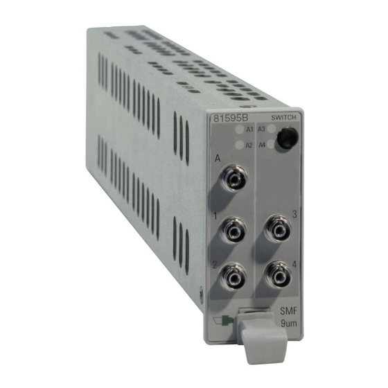
Introduction Getting Started 81591B: 1 x 2 81594B: 2 x 2 (Crossover) 81595B: 1 x 4 Figure 2 Switch Module Configurations How to Toggle the Switch Path You can use [Toggle] softkey in the mainframe User Interface, or the Toggle button located on the Optical Switch module front panel, to select each of the available routes for a channel in turn. -
Page 13: Typical Applications
Getting Started Introduction Typical Applications The following section shows just a few of the possibilities available for use of the switch modules to achieve better test automation, and test repeatability. 1 x 2 Switch Select one of two different sources (different wavelengths) as the input to the DUT. - Page 14 Introduction Getting Started 2 x 2 Switch Select an optional optical path, in the case shown here it is a fiber spool. Bypass position input output signal fiber spool Insert position input output signal fiber spool Figure 5 Circuit selection with crossover switch (for example in dispersion penalty test setup) Agilent 8159xB Optical Switch Modules, Fourth Edition Artisan Technology Group - Quality Instrumentation ...
- Page 15 Getting Started Introduction 1 x 4 Switch Select one from several test objects in parallel test setups, as shown in the following diagram. 1 x 4 switch 1 x 4 switch Analyzing Source Instruments Figure 6 Selection of one from several DUTs in parallel test setups Alternatively this switch can be used to automatically select one from up to four different analyzing instruments.
-
Page 16: Accessories
Accessories The Agilent 81591B, 81594B and 81595B optical switch modules are available in option addressing single mode and multimode applications. This chapter provides information on the available options. Modules and Options ......14 Agilent 8159xB Optical Switch Modules, Fourth Edition Artisan Technology Group - Quality Instrumentation ... -
Page 17: Modules And Options
OPTICAL SWITCH MODULES Agilent Agilent Agilent Agilent Agilent Agilent 81591B #009 81594B #009 81595B #009 81591B #062 81594B #062 81595B #062 Angled FC connectors for single mode fibers Straight FC connectors for multimode fibers... -
Page 18: Specifications
Specifications Agilent 81591B, 81594B, 81595B optical switch modules are produced to the ISO 9001 international quality system standard as part of Agilent’s commitment to continually increasing customer satisfaction through improved quality control. Specifications describe the modules warranted performance. Supplementary performance characteristics describe the modules non- warranted typical performance. -
Page 19: Definition Of Terms
Specifications Definition of Terms Definition of Terms This section defines terms that are used both in this chapter and in “Performance Tests” on page 23. Specification: describes a guaranteed product performance that is valid under the specified conditions. (The confidence level used is 95%, as recommended by the ISO standard). -
Page 20: Insertion Loss (Il)
Definition of Terms Specifications Insertion loss (IL) The change of power level after inserting the optical switch set to transmission between two connectorized patchcords, expressed in dB. The insertion loss from input port i to output port j is calculated from: where: = ower measured at the end of the two connected patch cords (see drawing). -
Page 21: Operating Temperature
Specifications Definition of Terms Operating Temperature TThe range of ambient temperatures for which the specifications apply. For a device mounted in a rack the environmental conditions within the N O TE rack apply. Polarization dependent loss (PDL) The dependence of the Insertion loss (IL) on the input polarization state, expressed as the difference (in dB) between the lowest and highest... -
Page 22: Return Loss
Definition of Terms Specifications Return loss Minimum ratio between incident power and reflected power over all switch states, expressed in dB. The return loss RL for any input port is calculated from: Where Pinc is the incident power, P,ref is the reflected power and MINs{} is the minimum over all switch states. -
Page 23: Wavelength Range
Specifications Definition of Terms Wavelength range Specifies the wavelength range for which the specifications apply (if not differently stated). Literature [1] Fiber optic test and measurement, Hewlett Packard Professional Books, edited by Prentice Hall, ISBN 0-13-534330-5 [2] GR -1073-CORE, Generic Requirements for Single Mode Fiber Optic Switches (Issue 1, January 2001, Telcordia Technologies) Agilent 8159xB Optical Switch Modules, Fourth Edition... -
Page 24: Specifications
Specifications Specifications Specifications Table 2 Optical Switch Module Specifications Product Number 81591B 81594B 81595B Switch type 1 x 2 2 x 2 1 x 4 #009 #062 #009 #062 #009 #062 Fiber interface single mode multimode single mode multimode single mode multimode 9/125 µm... - Page 25 Specifications Specifications Ordering Information: Modules for single mode fiber interface: #009 Modules for multimode fiber interface: #062 Agilent 8159xB Optical Switch Modules, Fourth Edition Artisan Technology Group - Quality Instrumentation ... Guaranteed | (888) 88-SOURCE | www.artisantg.com...
-
Page 26: Performance Tests
Performance Tests The performance tests in this section test the optical performance of the Agilent 8159xB optical switches modules. The complete specifications to which the instrument is tested are given in “Specifications” on page 15. All tests can be performed without access to the interior of the instrument. The performance tests refer specifically to tests using an Agilent reference connector. -
Page 27: Required Test Equipment
81000UM 1 1 1 1. Diamond AMCB-180-00V062 2. Service tool. For use in Agilent Technologies Service Center only. Buffered Reference Fiber 62.5µm Agilent 8159xB Optical Switch Modules, Fourth Edition Artisan Technology Group - Quality Instrumentation ... Guaranteed | (888) 88-SOURCE | www.artisantg.com... -
Page 28: Test Record
Agilent Technologies. Test Failure If the Agilent 8159xB Modular Optical Switch fails any performance test, return the instrument to the nearest Agilent Technologies Sales/Service Office for repair. Instrument Specification Specifications are the performance characteristics of the instrument that is certified. -
Page 29: Performance Test Procedures
Performance Tests Performance Test Procedures Performance Test Procedures The performance tests given in this section includes the Repeatability Test. Perform each step in the order given, using the corresponding test equipment. Make sure that all optical connections of the test setup given in the N O TE procedure are dry and clean. -
Page 30: Insertion Loss Test
Performance Test Procedures Performance Tests Insertion Loss Test Carry out the following Insertion Loss Test for 8159xB #009 at 1310 nm and 1550 nm, and for 8159xB #062 at 850nm and 1310nm using the equipment listed in Table 3 on page 24. To adapt for the straight or angled contact versions of the optical switch use patch cords with appropriate connectors and suitable connector interfaces. - Page 31 Performance Tests Performance Test Procedures Insertion Loss Measurement Set the power meter averaging time to 200ms Enable the laser source and set <Display to Reference> on the power meter Connect the equipment as shown in Figure 14. For 81594B, connect the laser source to input A, first.
- Page 32 Performance Test Procedures Performance Tests This test should be completed within 15 minutes because of stability and N O TE drift reasons. Else a new reference measurement has to be performed. On the laser source, select the second wavelength as listed in the Test Record Repeat step 4 to step 11 Agilent 8159xB Optical Switch Modules, Fourth Edition...
-
Page 33: Repeatability Test
Performance Tests Performance Test Procedures Repeatability Test Carry out the following Repeatability Test for 8159xB #009 at 1550 nm, and for 8159xB #062 at 850nm using the equipment listed in Table 3 page 24. Use the same equipment and test set up as used in Figure 14 page 28. - Page 34 Performance Test Procedures Performance Tests Test Record Agilent Modular Optical Switch Performance Test Page 1 of 4 Test Facility: Report No.: Date: Customer: Tested By: Model: Agilent Modular Optical Switch Product Number: ° Serial No. Ambient temperature Firmware Rev. Relative humidity Line frequency Special Notes: Agilent 8159xB Optical Switch Modules, Fourth Edition...
- Page 35 Performance Tests Performance Test Procedures Agilent Modular Optical Switch Performance Test Page 2 of 4 Agilent Modular Optical Switch Report No. Date: Test Equipment Description Model No. Trace No. Cal. due date Mainframe Power Meter Laser Source Mode Conditioner Mode Stripping Fiber Agilent 8159xB Optical Switch Modules, Fourth Edition Artisan Technology Group - Quality Instrumentation ...
- Page 36 Performance Tests Agilent Modular Optical Switch Performance Test Page 3 of 4 Agilent Modular Optical Switch Report No. Date Insertion Loss Test Product 81591B #009 81594B #009 81595B #009 Wavelength 1310 nm 1550 nm 1310 nm 1550 nm 1310 nm...
- Page 37 Performance Tests Performance Test Procedures Agilent Modular Optical Switch Performance Test Page 4 of 4 Agilent Modular Optical Switch Report No. Date Product 81595B #009 81595B #062 Wavelength 1550 nm 850 nm Ports A => 1 A => 2 A => 3 A =>...
-
Page 38: Cleaning Information
Cleaning Information Cleaning Instructions....... 36 Safety Precautions ........36 Why is it important to clean optical devices ? . -
Page 39: Cleaning Instructions
If you are unsure of the correct cleaning procedure for your optical device, we recommend that you first try cleaning a dummy or test device. Agilent Technologies assume no liability for the customer’s failure to comply with these requirements. Cleaning Instructions for this Module The Cleaning Instructions apply to a number of different types of Optical Equipment. -
Page 40: Why Is It Important To Clean Optical Devices
Cleaning Instructions Cleaning Information Why is it important to clean optical devices ? In transmission links optical fiber cores are about 9 µm (0.00035") in diameter. Dust and other particles, however, can range from tenths to hundredths of microns in diameter. Their comparative size means that they can cover a part of the end of a fiber core, and as a result will reduce the performance of your system. -
Page 41: What Do I Need For Proper Cleaning
• Pipe cleaner • Compressed air Dust and shutter All of Agilent Technologies’ lightwave instruments are delivered with caps either laser shutter caps or dust caps on the lightwave adapter. Any cables come with covers to protect the cable ends from damage or contamination. - Page 42 Cleaning Instructions Cleaning Information Do not use any other solvents, as some may damage plastic materials and cladding. Acetone, for example, will dissolve the epoxy used with fiber optic connectors. To avoid damage, only use isopropyl alcohol. Cotton swabs We recommend that you use swabs such as Q-tips or other cotton swabs normally available from local distributors of medical and hygiene products (for example, a supermarket or a chemist's shop).
- Page 43 Cleaning Information Cleaning Instructions Only use pipe cleaners on connector interfaces or on feed through adapters. Do not use them on optical head adapters, as the center of a pipe cleaner is hard metal and can damage the bottom of the adapter. Your pipe cleaner should be new when you use it.
- Page 44 Cleaning Instructions Cleaning Information Ultrasonic bath Ultrasonic baths are also available from photography or laboratory suppliers or specialist mail order companies. An ultrasonic bath will gently remove fat and other stubborn dirt from your optical devices. This helps increase the life span of the optical devices. Only use isopropyl alcohol in your ultrasonic bath, as other solvents may damage.
-
Page 45: Preserving Connectors
Keep the caps on the equipment always when it is not in use. All of Agilent Technologies’ lightwave instruments and accessories are shipped with either laser shutter caps or dust caps. If you need additional or replacement dust caps, contact your nearest Agilent Technologies Sales/Service Office. -
Page 46: Which Cleaning Procedure Should I Use
Cleaning Instructions Cleaning Information Which Cleaning Procedure should I use ? Light dirt If you just want to clean away light dirt, observe the following procedure for all devices: • Use compressed air to blow away large particles. • Clean the device with a dry cotton swab. •... -
Page 47: How To Clean Connectors
Cleaning Information Cleaning Instructions How to clean connectors Cleaning connectors is difficult as the core diameter of a single-mode fiber is only about 9 µm. This generally means you cannot see streaks or scratches on the surface. To be certain of the condition of the surface of your connector and to check it after cleaning, you need a microscope. -
Page 48: How To Clean Connector Interfaces
Cleaning Instructions Cleaning Information How to clean connector interfaces Be careful when using pipe-cleaners, as the core and the bristles of CAU T ION the pipe-cleaner are hard and can damage the interface. Do not use pipe-cleaners on optical head adapters, as the hard core of normal pipe cleaners can damage the bottom of an adapter. -
Page 49: How To Clean Bare Fiber Adapters
Cleaning Information Cleaning Instructions How to clean bare fiber adapters Bare fiber adapters are difficult to clean. Protect from dust unless they are in use. Never use any kind of solvent when cleaning a bare fiber adapter as CAU T ION solvents can damage the foam inside some adapters. -
Page 50: How To Clean Instruments With A Fixed Connector Interface
Cleaning Instructions Cleaning Information How to clean instruments with a fixed connector interface You should only clean instruments with a fixed connector interface when it is absolutely necessary. This is because it is difficult to remove any used alcohol or filaments from the input of the optical block. It is important, therefore, to keep dust caps on the equipment at all times, except when your optical device is in use. -
Page 51: Additional Cleaning Information
Cleaning Information Cleaning Instructions Additional Cleaning Information The following cleaning procedure may be used with other optical equipment: How to clean bare fiber ends Bare fiber ends are often used for splices or, together with other optical components, to create a parallel beam. The end of a fiber can often be scratched. -
Page 52: Other Cleaning Hints
Cleaning Instructions Cleaning Information Other Cleaning Hints Selecting the correct cleaning method is an important element in maintaining your equipment and saving you time and money. This Appendix highlights the main cleaning methods, but cannot address every individual circumstance. This section contain some additional hints which we hope will help you further. -
Page 53: Environmental Information
Cleaning Information Cleaning Instructions Environmental Information This product complies with the WEEE Directive (2002/96/EC) marking requirements. The affixed label indicates that you must not discard this electrical/ electronic product in domestic household waste. Product Category: With reference to the equipment types in the WEEE Directive Annex I, this product is classed as a "Monitoring and Control instrumentation"... -
Page 54: Index
Index Index Accessories, 13 Test equipment requirements, 24 Actuation Cycle, 16 Applications, 10 Wavelength range, 20 Cleaning connectors, 44 Cleaning Information, 35 Cross-over switch applications, 11 Crosstalk, 16 How to Toggle the Switch Path, 9 Insertion Loss, 17 Insertion loss test, 27 Introduction, 8 Maximum Input power, 17 Modules and Options, 14... - Page 55 Index Agilent 8159xB Optical Switch Modules, Fourth Edition Artisan Technology Group - Quality Instrumentation ... Guaranteed | (888) 88-SOURCE | www.artisantg.com...
- Page 56 Artisan Technology Group - Quality Instrumentation ... Guaranteed | (888) 88-SOURCE | www.artisantg.com...
- Page 57 Agilent Technologies GmbH 2005 Printed in Germany September 2005 Fourth edition, September 2005 81591-90B01 Agilent Technologies Artisan Technology Group - Quality Instrumentation ... Guaranteed | (888) 88-SOURCE | www.artisantg.com...
- Page 58 Artisan Technology Group is your source for quality new and certified-used/pre-owned equipment SERVICE CENTER REPAIRS WE BUY USED EQUIPMENT • FAST SHIPPING AND DELIVERY Experienced engineers and technicians on staff Sell your excess, underutilized, and idle used equipment at our full-service, in-house repair center We also offer credit for buy-backs and trade-ins •...