Table of Contents
Advertisement
Quick Links
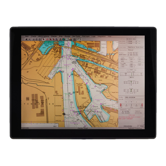
Marine Dash Board Panel PC
Intel® Pentium® N6415 (1.5M Cache, up to 3.0GHz)
User Manual
Part No. 91521110111U
Document Version 1.0
Please read these instructions carefully before using this product, and save this manual for future use
Model No. W10IE3S-MRH2FP
R12IE3S-MRM2FP
W12IE3S-MRB1FP
W15IE3S-MRB1FP
Advertisement
Table of Contents

Related Manuals for Winmate W10IE3S-MRH2FP


Summary of Contents for Winmate W10IE3S-MRH2FP
- Page 1 Marine Dash Board Panel PC Intel® Pentium® N6415 (1.5M Cache, up to 3.0GHz) Model No. W10IE3S-MRH2FP R12IE3S-MRM2FP W12IE3S-MRB1FP W15IE3S-MRB1FP User Manual Part No. 91521110111U Document Version 1.0 Please read these instructions carefully before using this product, and save this manual for future use...
-
Page 2: Table Of Contents
Marine Dash Board Panel PC User Manual Preface ........................2 Chapter 1: Introduction ..................6 1.1 Features ............................... 6 1.2 Package Contents ..........................6 1.3 Mechanical Dimensions ........................7 1.4 Connector Description .......................... 9 Chapter 2: Installation ..................10 2.1 Wiring Requirements .......................... 10 2.2 VESA Mounting .......................... -
Page 3: Preface
Chapter 1: Introduction Preface FCC Statement This device complies with part 15 FCC rules. Operation is subject to the following two conditions: This device may not cause harmful interference. This device must accept any interference received including interference that may cause undesired operation. - Page 4 Marine Dash Board Panel PC User Manual Copyright Notice No part of this document may be reproduced, copied, translated, or transmitted in any form or by any means, electronic or mechanical, for any purpose, without the prior written permission of the original manufacturer. Trademark Acknowledgement Brand and product names are trademarks or registered trademarks of their respective owners.
- Page 5 Chapter 1: Introduction Advisory Conventions Four types of advisories are used throughout the user manual to provide helpful information or to alert you to the potential for hardware damage or personal injury. These are Notes, Important, Cautions, and Warnings. The following is an example of each type of advisory.
- Page 6 According to the European Union issued Directive 2011/65/EU on the restriction of the use of certain hazardous substances in electrical and electronic equipment (RoHS 2.0). Winmate Inc.’s guaranty is able to meet the current regulations and customer requirements in respect of the application of cadium, lead, mercury,...
-
Page 7: Chapter 1: Introduction
Chapter 1: Introduction Chapter 1: Introduction The Marine Dash Board Panel PC runs on Intel® Pentium® N6415 processor. Multiple I/O interface includes USB 2.0, two LAN port, serial interface RS- 232/422/485 for machine-to-machine communications, USB 2.0 and USB 3.0 for data transfer. -
Page 8: Mechanical Dimensions
Marine Dash Board Panel PC User Manual 1.3 Mechanical Dimensions 10.1-inches, W10IE3S-MRH2FP Unit: mm Dimensions: 263.28x172x35.7 12.1-inches, R12IE3S-MRM2FP Unit: mm Dimensions: 296.2x226.7x45.5... - Page 9 Chapter 1: Introduction 12.3-inches W12IE3S-MRB1FP Unit: mm Dimensions: 325.02 x 146.5 x 45 14.9 inches W15IE3S-MRB1FP Unit: mm Dimensions: 400.1x 187.6 x 59...
-
Page 10: Connector Description
Marine Dash Board Panel PC User Manual 1.4 Connector Description Terminal interfaces are located on the bottom side of the HMI device. Note: Notice that input and output connectors vary by product size and specifications. Terminal interfaces description: Item Description 3-pin terminal block-DC terminal block power source input compact design meets the maritime application. -
Page 11: Chapter 2: Installation
Chapter 2: Installation Chapter 2: Installation 2.1 Wiring Requirements The following common safety precautions should be observed before installing any electronic device: Strive to use separate, non-intersecting paths to route power and networking wires. If power wiring and device wiring paths must cross make sure the wires are perpendicular at the intersection point. -
Page 12: Vesa Mounting
M4 x 6 14.9” 75x75 mm Installation Instruction Use Philips M4x5 screws to fix the desk stand to VESA holes on the back cover of the device. *The picture is for demonstration purposes only. VESA mount accessories are not supplied by Winmate. -
Page 13: Turning On
Chapter 2: Installation 2.3 Turning On Follow the following steps to turn on your device: 1. Connect AC adapter to DC jack connector of the HMI. 2. Connect the power cord to AC adapter. 3. Plug the power cord to the AC outlet. 4. -
Page 14: Connecting Peripherals
Marine Dash Board Panel PC User Manual 2.4 Connecting Peripherals This section lists HMI connectors and pin assignment. 2.4.1 Power Connector DC terminal block power source input compact design meets the maritime application. The 3-pin terminal block is to be secured that the cable to screw terminal. -
Page 15: Serial Port Connector
Chapter 2: Installation 2.4.3 Serial Port Connector Use COM1 serial port connector to connect your HMI to external devices such as mouse, modem or printer. You can configure serial port settings via jumpers located on the motherboard. Pin assignment and signal names of serial port connector Pin №... -
Page 16: Hdmi Connector
Marine Dash Board Panel PC User Manual 2.4.5 HDMI Connector The HMI has one HDMI1.4a connector. Pin assignment and signal name of HDMI connector Pin No. Signal Name Pin No. Signal Name HDMI_DET HDMI_D2P HDMI_D2M HDMI_D1P HDMI_D1M HDMI_D0P HDMI_D0M HDMI_CLKP HDMI_CLKM HDMI_CEC_OUT DDC_CLOCK... -
Page 17: Speaker
Chapter 2: Installation 2.5 Speaker Speaker is located on the rear side of the HMI. Electrical Specifications Rated impedance 6±15% ohms@2KHz, 1 Vrms input Power Rating 0.67 W Short Term Max Power 1.3W Acoustical Specifications Sound Pressure Level 75±3dB/40cm@1kHz... -
Page 18: Chapter 3: Operating The Device
Marine Dash Board Panel PC User Manual Chapter 3: Operating the Device 3.1 Introduction Your HMI supports several versions of Windows OS: Windows Embedded 8.1 Industry Pro Windows 10 IoT Windows 11 IoT Enterprise SAC Important: The device is shipped with the OS System according to your order. Contact us if you have any questions regarding OS settings. -
Page 19: How To Enable Watchdog
Chapter 3: Operating the Device 3.2 How to Enable Watchdog To enable Watchdog, you need to download Winmate Watchdog utility. Find more information on Watchdog in “Watchdog Guide” that you can download from Winmate Download Center. To enable watchdog in Watchdog AP follow the instructions below: 1. -
Page 20: Using Recovery Wizard To Restore Computer
Marine Dash Board Panel PC User Manual 3.3 Using Recovery Wizard to Restore Computer Note: Before starting the recovery process, make sure to backup all user data. The data will be lost after the recovery process. To enable quick one-key recovery procedure: 1. -
Page 21: Chapter 4: Bios Setup
Chapter 4: BIOS Setup Chapter 4: BIOS Setup This chapter describes the different settings available in the INSYDE BIOS that comes with the board. This chapter offers information on the Award BIOS installation utility. 4.1 How and When to Use BIOS Setup 4.2 BIOS Functions 4.1 How and When to Use BIOS Setup To enter the BIOS setup, you need to connect an external USB keyboard, external... - Page 22 Marine Dash Board Panel PC User Manual The following Keys can be used after entering the BIOS Setup. Function General Help Previous Values Optimized Defaults Save & Exit Exit Change Opt. Enter Select or execute command Cursor ↑ Moves to the previous item Cursor ↓...
-
Page 23: Bios Functions
Chapter 4: BIOS Setup 4.2 BIOS Functions 4.2.1 Main Menu The Main menu displays the basic information about yoursystem including BIOS version, processor RC version, system language, time, and date. When you enter BIOS setup, the first menu that appears on the screen is the main menu.It contains the system information including BIOS version, processor RC version, system language, time, and date. -
Page 24: Advanced Settings
Marine Dash Board Panel PC User Manual 4.2.2 Advanced Settings Select the Advanced Tab from the setup menu to enter the advanced BIOS setup screen. You can select any of the items on the left frame of the screen to go to the sub menu for the item, such as CPU Configuration. - Page 25 Chapter 4: BIOS Setup 4.2.2.1 Super I/O Configuration Serial Port 1 Configuration Serial Port This item enables or disables Serial Port (COM). Options: Enabled (Default) / Disabled Change Settings This item allows you to select an optimal setting for Super IO device. Options: Auto (Default) / IO=3F8h;...
- Page 26 Marine Dash Board Panel PC User Manual 4.2.2.2 Hardware Monitor 4.2.2.3 CPU Configuration Active Processor Cores This item sets number of cores to enable in each processor package Options: All (Default) / 1 Limit CPUID Maximum When the computer is booted up, the operating system executes the CPUID instruction to identify the processor and its capabilities.
- Page 27 Chapter 4: BIOS Setup Options: Disabled (Default) / Enabled Execute-Disable Bit XD can prevent certain classes of malicious buffer overflow attacks when combined with a supporting OS (Windows Server 2003 SP1, Windows XP SP2, SuSE Linux 9.2, RedHat Enterprise 3 Update 3.). Options: Enabled (Default) / Disabled Hardware Prefetcher The processor has a hardware prefetcher that automatically analyzes its...
- Page 28 Marine Dash Board Panel PC User Manual Package C state limit This item enables or disables package C state limit Options: No Limit (Default) / CO / C1 / C3 / C6 / C7 4.2.2.4 PPM Configuration EIST This item enables or disables Intel SpeedSteps. Options: Enabled (Default) / Disabled CPU C state Report This item enables or disables CPU C state report to OS.
- Page 29 Chapter 4: BIOS Setup 4.2.2.5 SATA Configuration Serial-ATA (SATA) This item enables/disables Serial ATA Device. Options: Enabled (Default) / Disabled SATA ODD Port This item selects SATA ODD Port Options: No ODD (Default) / Port0 ODD / Port1 ODD SATA Mode This item determines how SATA controller(s) operate.
- Page 30 Marine Dash Board Panel PC User Manual 4.2.2.6 Network Stack Configuration Network Stack This item enables or disables UEFI network stack Options: Disabled (Default) / Enabled Note: The following items appear only when you set the Network Stack function to [Enabled] IPv4 PXE Support This item enables or disables IPv4 PXE Boot Support.
- Page 31 Chapter 4: BIOS Setup 4.2.2.7 CSM Configuration CSM Support This item enables or disables CSM Support Options: Disabled (Default) / Enabled Note: The following items appear only when you set the CSM Support to [Enabled] GateA20 Active Upon Request – FA20 can be disabled using BIOS services. Always – do not allow disabling GA20;...
- Page 32 Marine Dash Board Panel PC User Manual Storage This option controls the execution of UEFI and Legacy Storage OpROM Options: Legacy only (Default) / Do not launch / UEFI only / Legacy first / UEFI first Video This option controls the execution of UEFI and Legacy Video OpROM Options: Legacy only (Default) / Do not launch / UEFI only / Legacy first / UEFI first Other PCI devices...
- Page 33 Chapter 4: BIOS Setup Legacy USB Support This item determines if the BIOS should provide legacy support for USB devices like the keyboard, mouse, and USB drive. This is a useful feature when using such USB devices with operating systems that do not natively support USB (e.g. Microsoft DOS or Windows NT).
-
Page 34: Chipset Menu
Marine Dash Board Panel PC User Manual 4.2.3 Chipset Menu This section describes configuring the PCI bus system. PCI, or Personal Computer Interconnect, is a system which allows I/O devices to operate at speeds nearing the speed of the CPU itself uses when communicating with its own special components. - Page 35 Chapter 4: BIOS Setup 4.2.3.1 North Bridge Intel IGD Configuration Integrated Graphics Device Enable: Enable Integrated Graphics Device (IGD) when selected as the Primary Video Apaptor. Disable: Always disable IGD. Options: Enabled (Default) / Disabled IGD Turbo Enable Enable: Enable IGD Turbo Enable. Disable: Enable IGD Turbo Disable. Options: Enabled (Default) / Disabled Primary Display This item selects which of IGD/PCI Graphics device should be Primary...
- Page 36 Marine Dash Board Panel PC User Manual Options: Enabled (Default) / Disabled LCD Control Boot Display Device This item allows you to select the display device. Options: Auto (Default) Max TOLUD This item sets maxium value of TOLUD. Options: Dynamic (Default) / 1GB / 1.25GB / 1.5GB / 1.75GB / 2GB / 2.25GB / 2.5GB / 2.75GB / 3GB 4.2.3.2 South Bridge Azalia HD Audio...
- Page 37 Chapter 4: BIOS Setup Options: 11dB (Default) / 14dB / 19dB / 25dB USB Configuration XHCI Mode The item selects Mode of operation of xHCI controller. Options: Smart Auto (Default) / Auto / Enabled / Disabled USB 2.0(EHCI) Support This item controls the USB EHCI (USB 2.0) functions. One EHCI controller must always be enabled.
-
Page 38: Security Menu
Marine Dash Board Panel PC User Manual 4.2.4 Security Menu This section allows to configure and improve system, and set up some system features according to your preferences. Administrator Password This item sets Administrator Password. User Password This item sets User Password. Secure Boot Secure Boot can be enabled if 1. - Page 39 Chapter 4: BIOS Setup Key Management Enroll All Factory Default Keys It allows you to immediately load/clear the default Security Boot keys, Platform key (PK), Key-exchange Key (KEK), Signature database (db), and Revoked Signatures (dbx). The Platform Key (PK) state will change from Unloaded mode to Loaded mode.
-
Page 40: Boot Menu
Marine Dash Board Panel PC User Manual 4.2.5 Boot Menu Setup Prompt Timeout This item sets number of seconds to wait for setup activation key. Options: 2 (Default) Bootup NumLock State This item selects the keyboard NumLock state. Options: On (Default) / Off Full Screen Logo Display This item allows you to enable/disable Full Screen Logo Show function. -
Page 41: Exit Menu
Chapter 4: BIOS Setup 4.2.6 Exit Menu This menu allows you to load the optimal default settings, and save or discard the changes to the BIOS items. Discard Changes and Exit Abandon all changes made during the current session and exit setup. Save Changes and Reset Reset the system after saving the changes. -
Page 42: Appendix
Marine Dash Board Panel PC User Manual Appendix Appendix A: Product Specifications Model Name W10IE3S-MRH2FP R12IE3S-MRM2FP Display Size 10.1” 12.1” Resolution 1280 x 800 1024x768 500 nits Panel Brightness 350.0 nits 1000 nits(Optional) Contrast Ratio 800:1 1000:1 View Angles 85,85,85,85... - Page 43 Appendix Model Name W12IE3S-MRB1FP W15IE3S-MRXB1FP Display Size 12.3” 14.9” Resolution 1920 x 720 1920 x 720 Panel Brightness 1000.0 nits 950.0 nits Contrast Ratio 1000:1 1000:1 View Angles 88,88,88,88 85,85,85,85 Touch/Glass Projected Capacitive Multi Touch Projected Capacitive Multi Touch Active Area 355.68×133.38 mm Mechanical Dimensions...
-
Page 44: Appendix B: Cleaning The Lcd Monitor
Don not use water or oil directly on the display screen. If droplets are allowed to drop on the screen, permanent staining or discoloration may occur. Appendix C: Technical Support Winmate provides the following Drivers, SDK and Update Guide: Item Driver Description Utility... - Page 45 Notes ___________________________________________________________________ ___________________________________________________________________ ___________________________________________________________________ ___________________________________________________________________ ___________________________________________________________________ ___________________________________________________________________ ___________________________________________________________________ ___________________________________________________________________ ___________________________________________________________________ ___________________________________________________________________ ___________________________________________________________________ ___________________________________________________________________ ___________________________________________________________________ ___________________________________________________________________ ___________________________________________________________________ ___________________________________________________________________ ___________________________________________________________________ ___________________________________________________________________ ___________________________________________________________________ ___________________________________________________________________ ___________________________________________________________________ ___________________________________________________________________ ___________________________________________________________________ ___________________________________________________________________ ___________________________________________________________________ ___________________________________________________________________ ___________________________________________________________________ ___________________________________________________________________ ___________________________________________________________________ ___________________________________________________________________...
- Page 46 Notes ___________________________________________________________________ ___________________________________________________________________ ___________________________________________________________________ ___________________________________________________________________ ___________________________________________________________________ ___________________________________________________________________ ___________________________________________________________________ ___________________________________________________________________ ___________________________________________________________________ ___________________________________________________________________ ___________________________________________________________________ ___________________________________________________________________ ___________________________________________________________________ ___________________________________________________________________ ___________________________________________________________________ ___________________________________________________________________ ___________________________________________________________________ ___________________________________________________________________ ___________________________________________________________________ ___________________________________________________________________ ___________________________________________________________________ ___________________________________________________________________ ___________________________________________________________________ ___________________________________________________________________ ___________________________________________________________________ ___________________________________________________________________ ___________________________________________________________________ ___________________________________________________________________ ___________________________________________________________________ ___________________________________________________________________...
- Page 47 Notes ___________________________________________________________________ ___________________________________________________________________ ___________________________________________________________________ ___________________________________________________________________ ___________________________________________________________________ ___________________________________________________________________ ___________________________________________________________________ ___________________________________________________________________ ___________________________________________________________________ ___________________________________________________________________ ___________________________________________________________________ ___________________________________________________________________ ___________________________________________________________________ ___________________________________________________________________ ___________________________________________________________________ ___________________________________________________________________ ___________________________________________________________________ ___________________________________________________________________ ___________________________________________________________________ ___________________________________________________________________ ___________________________________________________________________ ___________________________________________________________________ ___________________________________________________________________ ___________________________________________________________________ ___________________________________________________________________ ___________________________________________________________________ ___________________________________________________________________ ___________________________________________________________________ ___________________________________________________________________ ___________________________________________________________________...
- Page 48 Winmate Inc. 9F, No.111-6, Shing-De Rd., San-Chung District, New Taipei City 24158, Taiwan, R.O.C www.winmate.com Copyright © 2023 Winmate Inc. All rights reserved.
Need help?
Do you have a question about the W10IE3S-MRH2FP and is the answer not in the manual?
Questions and answers