Advertisement
Quick Links
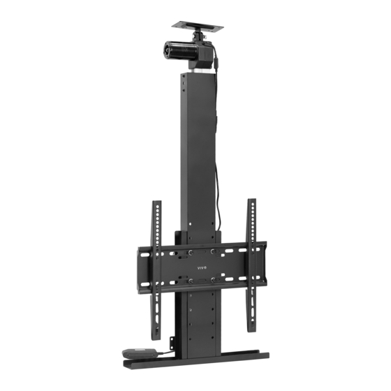
Motorized Drop Down TV Mount
with Remote Control
Instruction Manual
SKU: MOUNT-E-DN55
Scan the QR code with your mobile device or follow the link
for helpful videos and specifications related to this product.
https://vivo-us.com/products/mount-e-dn55
GET IN TOUCH | Monday-Friday from 7:00am-7:00pm CST
help@vivo-us.com
www.vivo-us.com
Chat live with an agent!
309-278-5303
Advertisement

Subscribe to Our Youtube Channel
Related Manuals for Vivo MOUNT-E-DN55


Summary of Contents for Vivo MOUNT-E-DN55
- Page 1 Motorized Drop Down TV Mount with Remote Control Instruction Manual SKU: MOUNT-E-DN55 Scan the QR code with your mobile device or follow the link for helpful videos and specifications related to this product. https://vivo-us.com/products/mount-e-dn55 GET IN TOUCH | Monday-Friday from 7:00am-7:00pm CST help@vivo-us.com...
-
Page 2: Package Contents
WARNING! If you do not understand these directions, or if you have any doubts about the safety of the installation, please call a qualified technician. Check carefully to make sure there are no missing or defective parts. Improper installation may cause damage or serious injury. -
Page 3: Assembly Steps
ASSEMBLY STEPS STEP 1 Plug Control Unit (F) and AC Adapter (G) into Lift Column (A). Plug Power Cable (J) into AC Adapter (G) and then connect to an outlet. STEP 2 Perform the PAIRING THE REMOTE steps on page 10 to pair RF Remote (H). Once RF Remote (H) is paired, press the down arrow and extend Lift Column (A) until the last hole set has passed Wall Mounting Plate (A1) as shown. - Page 4 STEP 3 Install Extension Brackets (D) to Lift Column (A) using M6x6mm Screws (S-C) and 4mm Allen Wrench (T-B). The location will be dependent on the TV size and VESA hole location. STEP 4 Install Cover Mount (E) onto Extension Brackets (D) using M6x10mm Screws (S-D) and 4mm Allen Wrench (T-B).
- Page 5 STEP 5 Attach VESA Plate (B) to Lift Column (A) using M8x15mm Screws (S-E), M8 Washer (S-F), M8 Nut (S-G), 13mm Wrench (T-A), and a Phillips screwdriver. Make sure the arrow on VESA Plate (B) is facing towards the motor. NOTE: The nuts and washers MUST be installed on the front of the VESA plate to prevent...
- Page 6 STEP 7 Wood Installation: Hold Ceiling Plate (I) up to desired mounting location making sure one of the long edges is making contact with the back support wall. Secure Ceiling Plate (I) using ST5.5x16mm Screws (W-A) and a drill. Concrete/Brick Installation: Hold Ceiling Plate (I) up to desired mounting location making sure one of the long edges is making contact with the back support wall.
- Page 7 STEP 8 Align the holes from Lift Column (A) and Ceiling Plate (I). Insert Clevis Pin (S-A) through the motor and Ceiling Plate (I). Insert Cotter Pin (S-B) into Clevis Pin (S-A) to secure. STEP 9 Ensure that Wall Mounting Plate (A1) is not blocked by VESA Plate (B).
- Page 8 STEP 10 Concrete/Brick Installation: Mark Wall Mounting Plate (A1) hole locations using a pencil or marker. Remove Lift Column (A) from Ceiling Plate (I) or hold away from the wall. Drill 1.8”/45mm deep holes using a 5/16”/8mm drill bit. Insert Concrete Anchors (W-C) and install Lift Column (A) using ST5.5x38mm Screws (W-B) and a Phillips screwdriver.
- Page 9 STEP 12 Hang VESA Brackets (C) over VESA Plate (B) and tighten safety screws using a Phillips screwdriver. STEP 13 Mount is now ready for use. Refer to remote instructions on the next page for further information on use, troubleshooting, and more.
-
Page 10: Pairing The Remote
RF Remote - Manual PAIRING THE REMOTE: button on Control Unit (F). The status light on the control unit will turn Step 1: Double press the on indicating you have entered programming mode. Step 2: Press and hold the buttons simultaneously on the remote until the status light stops flashing. -
Page 11: Troubleshooting
3. Program Coding Error: The remote may not have been properly coded. Please follow “Pairing the Remote” steps again. 4. Faulty Remote or Control Box: If mount is still unresponsive, the remote or control unit may be faulty. Please contact our Product Support Team at 309-278-5303 or help@vivo-us.com. - Page 12 AVG. RESPONSE TIME (within office hrs) - 23% within < 15m - 38% within < 30m - 61% within < 1hr - 83% within < 2hr - 92% within < 3hr FOR MORE VIVO PRODUCTS, CHECK OUT OUR WEBSITE AT: www.vivo-us.com...
Need help?
Do you have a question about the MOUNT-E-DN55 and is the answer not in the manual?
Questions and answers