Advertisement
Quick Links
092474 RevE
HCC 1000
®
Automated Controller
Owner's Manual
\
Contents
Introduction............................................3
Installation..............................................5
Pool Chemistry .......................................7
Configuration..........................................7
Display Functions..................................13
System Maintenance.............................15
Troubleshooting....................................16
Warranty...............................................22
HCC1000-PH
HCC1000-CO2
Hayward Pool Products
620 Division Street, Elizabeth NJ 07207
Phone (908)-355-7995
www.hayward.com
USE ONLY HAYWARD GENUINE REPLACEMENT PARTS
Advertisement

Subscribe to Our Youtube Channel
Related Manuals for Hayward HCC 1000


Summary of Contents for Hayward HCC 1000
-
Page 1: Table Of Contents
HCC 1000 ® Automated Controller Owner’s Manual Contents Introduction..........3 Installation..........5 Pool Chemistry ........7 Configuration..........7 Display Functions........13 System Maintenance......15 Troubleshooting........16 Warranty..........22 HCC1000-PH HCC1000-CO2 Hayward Pool Products 620 Division Street, Elizabeth NJ 07207 Phone (908)-355-7995 www.hayward.com USE ONLY HAYWARD GENUINE REPLACEMENT PARTS... - Page 2 • • WARNING: Risk of Electric Shock. Connect controller only to a grounding type recepta- cle protected by a ground-fault circuit interrupter (GFI). Hayward recommends installation to a dedicated GFI circuit breaker performed by a licensed electrician. • WARNING: Disconnect power before servicing. Other than the fuses, there are no user serviceable parts inside the controller.
- Page 3 Foreword Congratulations on your wise investment. The product you have selected from the Hayward line ® of automated controllers should provide you with substantially reduced chemical maintenance, im- proved compliance with Health Department operating standards, chemical cost savings, and many years of reliable operation.
-
Page 4: Introduction
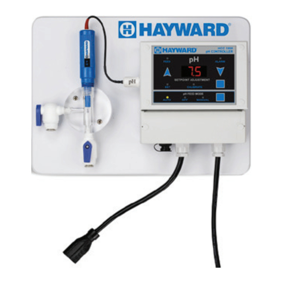
The ideal pH range for pools and spas is 7.4 - 7.6. The HCC 1000 controller is preset from the factory to maintain pH 7.5. If pH is maintained below 7.4 (too acidic), eye irritation, corrosion of equipment, and damage to the pool or spa surface can occur. - Page 5 The Flow Cell provides a convenient location for mounting the pH sensor while ensuring ideal hydraulic conditions to maximize sensor performance and life. The HCC 1000 controller unit scans and interprets the signals from the pH sensor, displays water quality readings in digital format, and activates chemical feeder in proportion to the demand re- quired to maintain the pH setpoint level.
-
Page 6: Installation
10. If new or additional chemical feeders are to be used with the controller, install according to manufacturers instructions at this time. 11. Connect chemical feeder to the controller as labeled. 12. Check all electrical and mechanical connections. Resume filtration system operation and check for any leaks. USE ONLY HAYWARD GENUINE REPLACEMENT PARTS... - Page 7 Typical HCC 1000 Installation Diagram USE ONLY HAYWARD GENUINE REPLACEMENT PARTS...
-
Page 8: Pool Chemistry
Selecting Acid or Base Feed The HCC 1000 is preset from the factory to operate in the acid feed mode (when pH exceeds the setpoint, the pH chemical feeder is activated). If the sanitizer used at your pool or spa causes the pH to decrease you must select base feed mode. - Page 9 Changing the pH Setpoint The HCC 1000 is preset from the factory to maintain pH at 7.5. To set pH control at a different level, perform the following: Press the pH Setpoint Adjustment Button (#4) until the green “SET” LED is illuminated.
- Page 10 MANUAL Advanced Configuration Options The HCC 1000 offers a host of advanced options to ensure compatibility with a wide variety of applications. The advanced programming menu contains features which are usually implemented during initial dealer setup and do not need to be routinely changed by the operator.
- Page 11 As the difference increases, the duration the pH feed output is turned on increases to 20, 30, 40, and 50 seconds of the 60 second cycle, and then the pH feed output is turned on continuously. This is the default setting. USE ONLY HAYWARD GENUINE REPLACEMENT PARTS...
- Page 12 P.OF (pH Overfeed Timer) Overfeed Timers prevent potentially dangerous, unintentional dispensing of chemicals. Hayward recommends always having the “Overfeed Timeout” function enabled as a precautionary measure. By disabling the “Overfeed Timeout” the overfeeding of chemicals could occur and create unsafe water chemistry conditions.
- Page 13 The Beeper setting allows the audible alarm to be enabled (default) or disabled. Srl (Serial Interface) The HCC 1000 includes a standard RS232 serial interface. A header assembly and cable are required to connect. Onl: Online Communications. Use this selection when the controller is attached to a PC or building automation system.
-
Page 14: Display Functions
Please refer to the Illustration on the following page with reference to designations of the various LED indicator lights on the front panel. Please note that for enhanced viewing the HCC 1000 fea- tures a “dead-front” display panel, so only illuminated indicators will be visible to the user. All lights and indicators are activated during power-on. - Page 15 HCC 1000 Indicator Designations & Functions DESIGNATION COLOR/TYPE DESCRIPTION GREEN LED pH FEED INDICATOR RED LED pH OUT OF RANGE ALARM DIGITAL DISPLAY pH INDICATOR/SETPOINT/CALIBRATION GREEN LED pH SETPOINT ADJUSTMENT MODE INDICATOR GREEN LED pH CALIBRATION MODE INDICATOR GREEN LED...
-
Page 16: System Maintenance
System Maintenance HCC 1000 Controller The HCC 1000 controller unit is virtually maintenance free. Cleaning of the enclosure, front panel and flow cell can be performed using a clean, soft cloth moistened with mild soap and water solution or glass cleaner. Use of abrasives or harsh chemicals may damage the enclosure and membrane switch panel. -
Page 17: Troubleshooting
Winterization The pH sensor should be prepared for storage as outlined above and protected from freezing tem- peratures. Although the HCC 1000 controller is designed to withstand a broad temperature range, winter storage in a secure location is desirable. The flow cell and poly tubing must be drained prior to exposure to freezing temperatures. Either purge all water using compressed air or thoroughly drain through the valve ports and tubing con- nections. - Page 18 Remote Alarm pH & Sensor: Casing Material Molded ABS Junction Type Teflon Reference Wet End ½” NPT Connector Shielded BNC Sensor Output Signal Requirements: 0-14 pH Power Input: 120/240 Volt AC, 10 AMP, 50/60 Hz USE ONLY HAYWARD GENUINE REPLACEMENT PARTS...
-
Page 19: Warranty
Three-Year Professional Series Sensor WARRANTY Hayward warrants the HCC 1000 automated controller to be free of defects ® in material and workmanship for a period of five years from date of ship- ment from our factory or authorized distributor. Liability under this warranty... - Page 20 Hayward is a registered trademark of Hayward Industries, Inc. © 2019 Hayward Industries, Inc. All other trademarks not owned by Hayward are the property of their respective owners. Hayward is not in any way affiliated with or endorsed by those third parties.
Need help?
Do you have a question about the HCC 1000 and is the answer not in the manual?
Questions and answers