Advertisement
092460 RevG
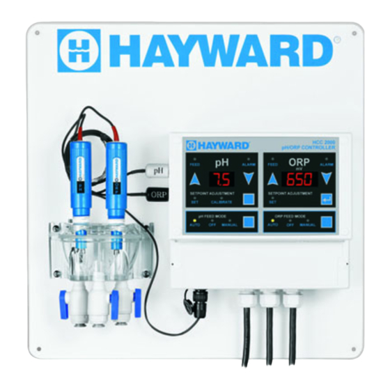
HCC 2000
®
Automated Controller
Owner's Manual
\
Contents
Introduction............................................3
Installation..............................................5
Pool Chemistry .......................................7
Configuration..........................................8
Display Functions..................................15
System Maintenance.............................17
Troubleshooting....................................19
Warranty...............................................22
HCC2000
HCC2000-AQ
HCC2000-AU
W3HCC2000
Hayward Industries
400 Connell Drive, Suite 6100
Berkeley Heights, NJ 07922
Phone: (908) 355-7995
www.hayward.com
USE ONLY HAYWARD GENUINE REPLACEMENT PARTS
Advertisement

Subscribe to Our Youtube Channel
Related Manuals for Hayward HCC 2000


Summary of Contents for Hayward HCC 2000
-
Page 1: Table Of Contents
Owner’s Manual Contents Introduction..........3 Installation..........5 Pool Chemistry ........7 Configuration..........8 Display Functions........15 System Maintenance......17 Troubleshooting........19 Warranty..........22 HCC2000 HCC2000-AQ HCC2000-AU W3HCC2000 Hayward Industries 400 Connell Drive, Suite 6100 Berkeley Heights, NJ 07922 Phone: (908) 355-7995 www.hayward.com USE ONLY HAYWARD GENUINE REPLACEMENT PARTS... - Page 2 • • WARNING: Risk of Electric Shock. Connect controller only to a grounding type recepta- cle protected by a ground-fault circuit interrupter (GFI). Hayward recommends installation to a dedicated GFI circuit breaker performed by a licensed electrician. • WARNING: Disconnect power before servicing. Other than the fuses, there are no user serviceable parts inside the controller.
- Page 3 Foreword Congratulations on your wise investment. The product you have selected from the Hayward line ® of automated controllers should provide you with substantially reduced chemical maintenance, im- proved compliance with Health Department operating standards, chemical cost savings, and many years of reliable operation.
-
Page 4: Introduction
The pH Sensor samples water from the filtration system and sends signals to the controller indi- cating the acidity of the water. The ideal pH range for pools and spas is 7.4 - 7.6. The HCC 2000 controller is preset from the factory to maintain pH 7.5. If pH is maintained below 7.4 (too acidic), eye irritation, corrosion of equipment, and damage to the pool or spa surface can occur. - Page 5 (redox) of the water. ORP is an actual measure of sanitizer activity (chlorine, bromine, ozone, etc.) and bacteriological water quality rather than an expression of chemical residual levels. The HCC 2000 controller is preset from the factory to maintain ORP at 650 millivolts.
-
Page 6: Installation
11. Connect chemical feeders to the controller as labeled (See diagram on following page). 12. Check all electrical and mechanical connections. Resume filtration system operation and check for any leaks. USE ONLY HAYWARD GENUINE REPLACEMENT PARTS... - Page 7 Typical HCC 2000 Installation Diagram: USE ONLY HAYWARD GENUINE REPLACEMENT PARTS...
-
Page 8: Pool Chemistry
Confirm that your pool or spa water conforms to the following ranges before powering on and setting up the HCC 2000. The table below indicates generally accepted guidelines. Always maintain water chemistry accord- ing to standards set by your local or State Health Department. -
Page 9: Configuration
Selecting Acid or Base Feed The HCC 2000 is preset from the factory to operate in the acid feed mode (when pH exceeds the setpoint, the pH chemical feeder is activated). If the sanitizer used at your facility causes the pH to decrease you must select base feed mode. - Page 10 Changing the pH Setpoint The HCC 2000 is preset from the factory to maintain pH at 7.5. To set pH control at a different level, perform the following: Press the pH Setpoint Adjustment Button (#4) until the green “SET” LED is illuminated.
- Page 11 About Proportional Feed The HCC 2000 features an advanced proportional feed algorithm which constantly analyzes demand for chemicals and initiates feeding in intervals based on the relationship between setpoint and actual water sample values.
- Page 12 OFF: The pH feed and ORP feed decisions are independent of each other. This is the default selection. On: The pH Priority feature is enabled. Inhibits the ORP feed output when the pH High Alarm is triggered. ORP feed will resume when pH High Alarm stops. USE ONLY HAYWARD GENUINE REPLACEMENT PARTS...
- Page 13 ORP Feed Mode indicator flashes rapidly to indicate the alarm. Press the ORP Feed Mode button to return the ORP channel to the off, manual or automatic feed mode. This will reset USE ONLY HAYWARD GENUINE REPLACEMENT PARTS...
- Page 14 The Beeper setting allows the audible alarm to be enabled (default) or disabled. Srl (Serial Interface) The HCC 2000 includes a standard Rs232 serial interface. A header assembly and cable are required to connect. USE ONLY HAYWARD GENUINE REPLACEMENT PARTS...
- Page 15 900: Use the UP and DOWN buttons to select a value between 400 and 995 mV. The value must be greater than the ORP alarm low value. The default value is 900 mV. USE ONLY HAYWARD GENUINE REPLACEMENT PARTS...
-
Page 16: Display Functions
LED is illuminated. pH Automatic Control Indicator (#6) This green LED is illuminated when pH is under automated control. pH Manual Off Indicator (#7) This red LED is illuminated when pH feeding is manually disabled. USE ONLY HAYWARD GENUINE REPLACEMENT PARTS... - Page 17 ORP Manual Off Indicator (#14) This red LED is illuminated when ORP feeding is manually disabled. ORP Manual On Indicator (#15) This green LED is illuminated when pH feeding is manually activated. HCC 2000 Indicator Designations & Functions DESIGNATION COLOR/TYPE DESCRIPTION...
-
Page 18: System Maintenance
System Maintenance HCC 2000 Controller The HCC 2000 controller unit is virtually maintenance free. Cleaning of the enclosure, front panel and flow cell can be performed using a clean, soft cloth moistened with mild soap and water solution or glass cleaner. Use of abrasives or harsh chemicals may damage the enclosure and membrane switch panel. - Page 19 Winterization The sensors should be prepared for storage as outlined above and protected from freezing tem- peratures. Although the HCC 2000 controller is designed to withstand a broad temperature range, winter storage in a secure location is desirable. The flow cell and poly tubing must be drained prior to exposure to freezing temperatures. Either purge all water using compressed air or thoroughly drain through the valve ports and tubing con- nections.
-
Page 20: Troubleshooting
Troubleshooting Each HCC 2000 controller is manufactured to the highest quality standards and then thoroughly tested before leaving the factory. State of the art design and fabrication technology ensure years of trouble free operation. Most apparent malfunctions can be solved through the following corrective actions: No lights are illuminated when controller is powered on. - Page 21 525 - 995 mV Default Settings: 650 mV Calibration Range: 2.0 pH +/- Control Accuracy: 0.1 pH 5.0 mV Mode Selections: pH Feed Auto/Off/Manual ORP Feed Auto/Off/Manual pH Selection Acid/Base pH Mode Auto/Set/Calibrate ORP Mode Auto/Set USE ONLY HAYWARD GENUINE REPLACEMENT PARTS...
- Page 22 1 AMP / Dry Contact ORP Feed 4 AMP / 120 VAC 4 AMP / 240 VAC 1 AMP / Dry Contact Remote Alarm 1 AMP / Dry Contact Optional Equipment: Chemical Feed Pumps pH Systems USE ONLY HAYWARD GENUINE REPLACEMENT PARTS...
-
Page 23: Warranty
WARRANTY Hayward warrants the HCC 2000 automated controller to be free of defects ® in material and workmanship for a period of one year from date of ship- ment from our factory or authorized distributor. Liability under this warranty is limited to the repair or replacement of any device or component which is returned to the factory within one year of delivery to original purchaser, ship- ping prepaid, and which is found to be defective upon examination. - Page 24 Hayward is a registered trademark of Hayward Industries, Inc. © 2020 Hayward Industries, Inc. All other trademarks not owned by Hayward are the property of their respective owners. Hayward is not in any way affiliated with or endorsed by those third parties.
Need help?
Do you have a question about the HCC 2000 and is the answer not in the manual?
Questions and answers