
Related Manuals for Hayward E-Command 4


Summary of Contents for Hayward E-Command 4
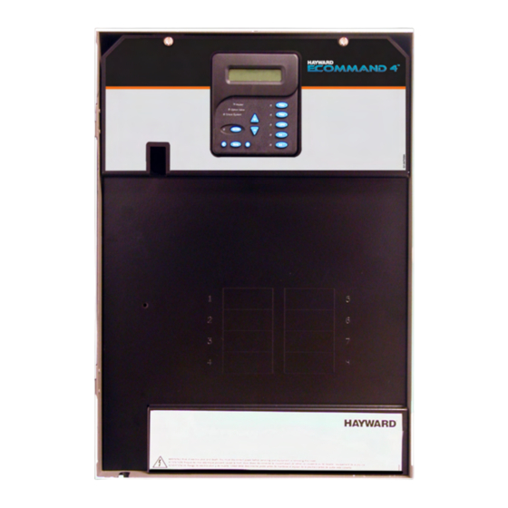
- Page 1 Hayward ECOMMAND 4 Automation Installation Manual for models HPC-4 HPC-4-ACT HPC-4-RC HPC-4-ACT-RC www.haywardnet.com...
- Page 2 IMPORTANT SAFETY INSTRUCTIONS When using this electrical equipment, basic safety precautions should always be followed, including the following: READ AND FOLLOW ALL INSTRUCTIONS • • WARNING: Disconnect all AC power during installation. • WARNING: Water in excess of 100 degrees Fahrenheit may be hazardous to your health.
-
Page 3: Table Of Contents
Table of Contents Introduction Before You Begin..............1 Installation Steps..............1 1. Mounting ECOMMAND 4 Control Center..........2 Equipment Temperature Sensors............2 Optional Wireless Remote Control........2 Optional Base Station............3 Optional Valve Actuators............3 2. Plumbing Plumbing Configuration............4 3. -
Page 4: Introduction Before You Begin
Wire/conduit for filter pump and other high voltage loads Wire for bonding Miscellaneous Mounting hardware (screws, etc.) for mounting ECOMMAND 4 Valves (use standard Hayward, Pentair/Compool, or Jandy valves) Additional valve actuators Accessory Products - Order Separately AQL2-SS-RF Wireless Spa Side Remote Control (Included with HPC-4-RC, HPC-4-ACT-RC) -
Page 5: Mounting Ecommand 4 Control Center
1. Mounting the Equipment ECOMMAND 4 Control Center The ECOMMAND 4 is contained in a raintight enclosure that is suitable for outdoor mounting. The control must be mounted a minimum of 5 ft. (2 meters) horizontal distance from the pool/spa (or more, if local codes require). -
Page 6: Optional Base Station
Optional Base Station (included with HPC-4-RC, HPC-4-ACT-RC) The AQL2-BASE-RF optional base station must be installed if the AQL2-SS-RF is used. To install the base station, remove the knockout on the upper left side of the ECOMMAND 4 main control unit, insert the base station, and then tighten the nut from the inside. -
Page 7: Plumbing Plumbing Configuration
2. Plumbing Pool/Spa system configuration These systems use a single filter pump and filter. Pool or spa operation is controlled by two 3-way valves (suction and return). Refer to the diagram below. HIGH VOLTAGE LIGHTS High Voltage Relays Valve Outputs LOW VOLTAGE Filter Pump Pool/Spa Suction... -
Page 8: Electrical Main Service
3. Electrical Wiring Wireless Base Receiver Connector Display/Keypad External Chlorinator (requires Aqua Rite) Sensor Input Heater Output Valve Connector High Voltage Relays Subpanel Control Power Input The ECOMMAND 4 Control Center requires both high and low voltage connections. Low voltage connections will be made to actuators, sensors, remote keypad, etc. -
Page 9: Circuit Breaker Installation And Wiring
Circuit Breaker Installation and Wiring Circuit breakers are to be supplied by the installer. Refer to the circuit breaker chart below for a list of suitable circuit breakers that can be used. Follow the code and the circuit breaker manufacturer’s rating requirements regarding the size and temperature rating for wiring. -
Page 10: High Voltage Pool Equipment
High Voltage (120/240V) Pool Equipment All ECOMMAND 4 relays are double pole (they make/break both “legs” of 240V circuits) and are rated at 3HP/30A at 240V (1½HP/30A at 120V). Refer to the diagram below for typical relay wiring. 240 VAC 120 VAC 120 VAC Load... -
Page 11: Low Voltage Wiring
Hayward Variable Speed Filter Pump: Proper installation of the Hayward TriStar Variable Speed Control (VSC) includes high voltage input wiring, communication wiring, and menu configuration/settings. Refer to the following diagram for proper input wiring to the VSC. Wiring from the 220V breaker must connect through the ECOMMAND 4’s Filter relay. - Page 12 Generic Heaters 1. Wire heater to 120/240V power source per the instructions in the heater manual. The ECOMMAND 4 does NOT control the power going to the heater. 2. Wire the ECOMMAND 4 dry contact heater output per the diagram below. Many internal parts of the heater can get very hot--see the heater manufacturer’s recommendations on the minimum temperature rating for wires.
- Page 13 Hayward Heaters Refer to the instructions in the heater manual for “2-wire Remote Thermostat” operation under “Remote Control Connections” and the diagram below: 1. Turn off power to heater. 2. Wire ECOMMAND 4 to terminals 1 & 2 (see diagram).
- Page 14 Raypak RP2100 Pool/Spa Heater 1. Turn power off to heater. 2. Push the mode button to “spa” mode. 3. Set the temperature to the maximum. 4. Push the mode button to “OFF”. 5. Lastly, plug the prewired connector in the P7 position on the board. IMPORTANT: The heater will display “OFF”...
- Page 15 Hayward Variable Speed Filter Pump: Refer to the diagram below for proper low voltage communica- tion wiring between the ECOMMAND 4 and the Hayward Tristar Variable Speed Control (VSC). Connect screw terminals “1” to “1”, “2” to “2”, etc. Use four conductor cable (typically phone cable) for communications connection between the VSC and the ECOMMAND 4.
- Page 16 Tighten nut Goldline Aqua Rite or Hayward Swimpure Chlorinator The ECOMMAND 4 can control one or more Goldline Aqua Rite or Hayward Swimpure chlorinators when additional sanitizing capacity is required. A 4 wire connection is used to communicate to the Aqua Rite/Swimpure and can be wired up to 500' apart.
-
Page 17: Configuration Configuration Menu
If the optional external chlorinator is enabled (requires the use of a Goldline Aqua Rite or Hayward Swimpure chlorinator), the ECOMMAND 4 will automatically chlorinate both the pool and spa according to the desired output setting (see Settings Menu in the Operation manual). - Page 18 Pool/Spa Config. Push to access Pool/Spa options + to view/change Move to previous/next configuration menu Rotates between Pool Only (default), Spa Only and Pool/Spa Setup Pool and Spa Pool and Spa Move to next menu item if “Pool and Spa” is selected Spa - CountDn Adjust time setting (Manual On/Off, 0:05, 0:10, 0:15..., (default is 4:00)) 00:30...
- Page 19 For the Hayward Tristar variable speed pump: The Filter relay is used to supply input power to the VSC pump control. The relay will be on when the filter pump output is on. When the filter pump output is off, the relay will be off.
- Page 20 Highest Speed This is the highest speed that the variable speed pump is allowed to run at. It is used as the upper limit in the High Speed Settings Menu. Also, this is the speed that the pump will run at during the first 3 minutes of operation anytime the pump has been off for more than 30 seconds.
- Page 21 Heater Extend If “Enabled”, the filter extend logic keeps the filter pump running beyond the normal turn-off time until the pool (or spa) is heated up to the desired temperature setting (see Settings Menu). Heater extend will NOT cause the filter pump to turn on, it will only delay the turn off time when the heater is operating.
- Page 22 Allow Low Speed This menu only appears if the pool filter is configured for 2-speed or variable speed operation. During default operation, high speed mode is used whenever the solar heater is on. If Allow Low Speed is enabled, low speed pump operation will be allowed during solar heating except for the first 3 minutes after solar heat turns on.
- Page 23 Super Chlorinate – if “Chlorinator” is enabled, this option allows the user to start a Super Chlorinate cycle when the Lights button is pressed, rather than using the Settings Menu. Note that only one button can be assigned to this function. Lights Relay This feature allows the user to select either “Standard”...
- Page 24 Aux1 Function Manual On/Off (default)—the aux relay will alternate between turning on and off when the aux button is pressed. There is no automatic control logic. Countdown Timer – the aux relay will turn on when the AUX button is pressed and then will turn off automatically after a programmed time (see Timers Menu, Operation Manual).
- Page 25 Valve3 Config. Push to access Valve3 options + to view/change Move to previous/next configuration menu Valve3 Function Rotates between Timecloc (default), Solar, In-floor Cleaner, Filter, Lights, Aux1 and Aux2 Solar Move to next menu item for all functions except solar and super chlorinate Valve3 Interlock Toggle between Enabled and Disabled (default) Valve3 Interlock Disabled...
- Page 26 Valve3 Pump Speed This is the speed of the pump when the Valve3 output is on. The choices are the Settings Menu speed and a speed that is unique to the Valve3 output only. The default selection is “Settings Menu”. This is the speed of the pump that has been selected in the Settings Menu for normal filter operation.
-
Page 27: System Startup Before Startup
5. System Startup and Checkout Before Startup Before starting the ECOMMAND 4 for the first time, be sure that the following items have been com- pleted: 1. Properly rated circuit breakers are installed in the ECOMMAND 4 subpanel. 2. All wiring is performed according to NEC and local codes. 3. -
Page 28: Service Mode
3. Once the heater is running, you can verify the “heater cooldown” feature (optional - see Configuration Menu/Heater Config.) is operating properly: • Press the “Filter” button once (for 2 speed pumps, this may require 2 pushes of the “Filter” button). -
Page 31: Warranty Ecommand 4 Limited Warranty
To obtain warranty service or repair, please contact the place of purchase or the nearest Goldline authorized warranty service center. For more information on authorized service centers please contact the Hayward/Goldline Technical Service Support Center ( 61 Whitecap Road, North Kingstown RI, 02852) or visit the Goldline web site, www.goldlinecontrols.com. - Page 32 ECOMMAND 4 Programming Flow Chart default menu day and time water temperature air temperature chlorinator setting denotes conditional items salt level reason pump is running (not scheduled) reason hi-speed is running (not scheduled) countdown time remaining heater control status system manual off check system error filter speed settings menu...
Need help?
Do you have a question about the E-Command 4 and is the answer not in the manual?
Questions and answers