Advertisement
092434 RevA
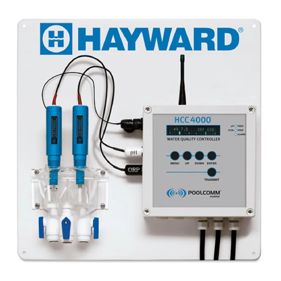
HCC 4000
®
Water Quality Controller
Owner's Manual
\
Contents
Introduction............................................2
Installation..............................................4
Pool Chemistry........................................7
Configuration..........................................7
System Maintenance.............................25
Network Communications.....................26
Troubleshooting....................................30
Warranty...............................................35
HCC4000
Hayward Pool Products
620 Division Street, Elizabeth NJ 07207
www.hayward.com
USE ONLY HAYWARD GENUINE REPLACEMENT PARTS
Advertisement

Related Manuals for Hayward HCC 4000


Summary of Contents for Hayward HCC 4000
-
Page 1: Table Of Contents
092434 RevA HCC 4000 ® Water Quality Controller Owner’s Manual Contents Introduction..........2 Installation..........4 Pool Chemistry........7 Configuration..........7 System Maintenance......25 Network Communications.....26 Troubleshooting........30 Warranty..........35 HCC4000 Hayward Pool Products 620 Division Street, Elizabeth NJ 07207 www.hayward.com USE ONLY HAYWARD GENUINE REPLACEMENT PARTS... - Page 2 WARNING: Always read and become familiar with Material Safety Data Sheets (MSDS) and safe handling instructions for all chemicals used with the controller. • CAUTION: The automatic controller should not be installed where it is accessible to the public. SAVE THESE INSTRUCTIONS USE ONLY HAYWARD GENUINE REPLACEMENT PARTS...
-
Page 3: Introduction
The results include elimination of “human error”, accurate and reliable maintenance of chemical levels twenty-four hours a day, compliance with Health Department operating standards, reduced burden on operating staff, and a reduction of chemical usage and costs. The HCC 4000 control- ler and POOLCOMM water quality management website together provide unprecedented control, access and documentation. - Page 4 The ideal pH range for pools and spas is 7.4 - 7.6. The HCC 4000 controller is preset from the factory to maintain pH 7.5. If pH is maintained below 7.4 (too acidic), eye irritation, corrosion of equipment, and damage to the pool or spa surface can occur.
-
Page 5: Installation
BNC Connector Protective Covers (Remove to Connect Sensors) 30’ Roll, Blue Poly Installation Tubing (3/8” OD) 1/4” NPT x 3/8” Tubing True-Seal Connectors HCC 4000 Quick Reference Guide 1/4” In-Line Strainer NOTE: Before commencing installation, please confirm that items listed above have been included. - Page 6 Mark tubing bottoms out and on tubing to release. 3/4” from end. This insertion mark is no Repeat steps 1 and 2 is the insertion mark. longer visible. to reuse fitting. O-Ring Tubing USE ONLY HAYWARD GENUINE REPLACEMENT PARTS...
- Page 7 Typical HCC 4000 Installation Diagram USE ONLY HAYWARD GENUINE REPLACEMENT PARTS...
-
Page 8: Pool Chemistry
Confirm that your pool or spa water conforms to the following ranges before powering on and setting up the HCC 4000. The table below indicates generally accepted guidelines. Always maintain water chemistry accord- ing to standards set by your local or State Health Department. - Page 9 To Change The Brightness Of The Display: The display intensity can be changed to accommodate comfortable viewing in a variety of lighting circumstances. While in normal operating mode: Press UP to increase display intensity. Press DOWN to decrease display intensity. USE ONLY HAYWARD GENUINE REPLACEMENT PARTS...
- Page 10 Setpoint To Change The pH Setpoint: The HCC 4000 is programmed at the factory with a default setpoint of pH 7.5. CAT Controllers considers this to be ideal for pool and spa applications. The following steps enable the selection of a different setpoint.
- Page 11 To Change The ORP Setpoint: The HCC 4000 is programmed at the factory to maintain ORP at 650 mV by default. This is the generally accepted world standard for safe drinking water. In order to maintain a given chlorine or...
- Page 12 To Select ORP Feed Mode: The HCC 4000 is programmed at the factory to operate in automatic feed mode as the default set- ting. Other ORP feed mode selections include off (disabled), and manual on for a fixed interval up to 25 minutes after which automatic feed will resume.
- Page 13 To Change The pH Control Mode: The HCC 4000 is programmed at the factory to operate in the acid feed mode by default (when pH exceeds setpoint, the pH chemical feeder is activated). If the sanitizer or other factors of the application cause the pH to decrease, base feed mode must be selected.
- Page 14 Priority: The HCC 4000 features a pH Priority setting which will inhibit ORP feed whenever pH is greater than .2 pH from the setpoint. This feature provides an important safeguard when sanitizers with a high pH (such as liquid chlorine) are used. From the Configuration Setup Menu: Press DOWN to find the pH Priority menu item.
- Page 15 The current pH Mixing Time Off setting will be displayed: Mixing Time Off Time 30 seconds Press UP or Down to scroll to desired setting. Press ENTER to save your selection. Press MENU to return to the Operating Menu. USE ONLY HAYWARD GENUINE REPLACEMENT PARTS...
- Page 16 Press ENTER to save your selection. Press MENU to return to the Operating Menu. NOTE: Overfeed Timers prevent potentially dangerous, unintentional dispensing of chemicals. CAT Controllers recommends always having the “Overfeed Timeout” functions enabled as a precaution- USE ONLY HAYWARD GENUINE REPLACEMENT PARTS...
- Page 17 ORP Feed: The HCC 4000 by default uses a time-based proportional feed algorithm which enables the precise control of virtually any body of water. With some types of chemical feeders, however, it is benefi- cial to disable proportional feed and dispense chemicals on a fixed basis. From the Configuration Setup Menu: Press DOWN to find the ORP Feed menu item.
- Page 18 From the Configuration Setup Menu: Press DOWN to find the ORP Overfeed Timeout menu item. Press ENTER to select ORP Overfeed Timeout. The current ORP Overfeed Timeout Setting will be displayed: USE ONLY HAYWARD GENUINE REPLACEMENT PARTS...
- Page 19 Press ENTER to save your selection. Alarm Setup: The Alarm Setup allows the audible alarm to be disabled without interfering with any other safe- guards or alerts to the POOLCOMM website. From the Configuration Setup Menu: USE ONLY HAYWARD GENUINE REPLACEMENT PARTS...
- Page 20 From the Configuration Setup Menu: Press DOWN to find the Auxiliary Output Setup menu item. Press ENTER to select Auxiliary Output Setup. The current Auxiliary Output selection will be displayed: AUX Output Setup Disabled USE ONLY HAYWARD GENUINE REPLACEMENT PARTS...
- Page 21 Press ENTER to select Digital Flow Alarm. The current Digital Flow Alarm setting will be displayed: Digital Flow Alarm Press UP or Down to scroll to desired setting. Press ENTER to save your selection. USE ONLY HAYWARD GENUINE REPLACEMENT PARTS...
- Page 22 After 10 seconds, the controller will revert to the Configuration Setup Menu. Update FW via BL: This feature is used to update firmware on the controller. Please contact Hayward Commercial at 301-838-4001 if you have firmware issues with your controller. From the Configuration Setup Menu: Press DOWN to find the Update FW via BL Menu item.
- Page 23 Demonstration Mode: The Demo Mode enables the HCC 4000 to be used as a demonstration, training, or sales aid. All functions, menus, and settings of the controller are active except that pH is simulated at 7.5 and ORP is simulated at 650 mV.
- Page 24 525 to 900 mV (Default 900 mV) ORP Overfeed Timer Off, 5 to 240 Minutes (Default 240 Min.) AUX pH Setpoint 0.0 to 14.0 (Default 7.5 pH) AUX ORP Setpoint 525 to 900 mV (Default 650 mV) USE ONLY HAYWARD GENUINE REPLACEMENT PARTS...
- Page 25 Digital Flow Alarm Digital Flow Sensor Type Blue, WHite or Signet Display System Information ENTER to Display Update FW via BL ENTER to run BL Restore Factory Defaults ENTER to Restore Demonstration Mode Off, USE ONLY HAYWARD GENUINE REPLACEMENT PARTS...
-
Page 26: System Maintenance
System Maintenance HCC 4000 Controller Package The HCC 4000 controller unit is virtually maintenance free. Cleaning of the enclosure, front panel and flow cell can be performed using a clean, soft cloth moistened with mild soap and water solution or glass cleaner. Use of abrasives or harsh chemicals may damage the enclosure and membrane switch panel. -
Page 27: Network Communications
Test w/ a HCC 4000 The best way to check for coverage at a facility is to test with an actual HCC 4000. The Transmit data button has been provided specifically for this purpose. Place the HCC 4000 unit where you expect to install it and press the transmit data button. - Page 28 Activating Communications To activate your first HCC 4000 wireless controller on the POOLCOMM web site you must first register an account. Call 301-838-4001 and ask for the POOLCOMM Program Administrator if you need assistance. Visit www.poolcomm.com from any internet-connected computer. Click on Register Account and complete all requested account information.
- Page 29 Red: A warning condition currently exists. Facility Name This field provides a list of facilities automated with HCC 4000 wireless controllers. Click on a facil- ity name to enter the Unit Profile for the controller. From the Unit Profile, the following settings can be modified online: Facility name, location and time zone information.
- Page 30 To update the website with the latest data from the HCC 4000, click the Get Data link at the bottom page. The following screen capture shows the settings which can be modified from the Unit Profile screen: Site Location This field is used to identify the specific asset being monitored (main pool, lap pool, spa, etc.) within the facility.
-
Page 31: Troubleshooting
Overfeed The pH Overfeed timeout occurs when the HCC 4000 has been feeding chemicals for a time greater than the selected maximum feed time and has not reached its setpoint. A properly selected Overfeed timeout prevents the unit from continuing to feed chemicals when the chemical supply has been diminished or a chemical feeder has become clogged or broken. - Page 32 Key Inserted When a service technician visits the HCC 4000 he may insert a service key (optional), which will be logged by the controller to document the time and duration of his visit.
- Page 33 Overfeed Timeout pH Priority Feed ORP Overfeed Timeout Supplemental Feed Modes Optional Equipment Optical Level Sensors Digital Flow Rate Sensor Rotary Flow Sensor Remote Dome Antenna Sensor Output Signal Requirements 0-14 pH, 0-1000mV ORP USE ONLY HAYWARD GENUINE REPLACEMENT PARTS...
- Page 34 USE ONLY HAYWARD GENUINE REPLACEMENT PARTS...
-
Page 35: Warranty
WARRANTY Hayward warrants the HCC 4000 automated controller to be free of defects ® in material and workmanship for a period of one year from date of ship- ment from our factory or authorized distributor. Liability under this warranty is limited to the repair or replacement of any device or component which is returned to the factory within five years of delivery to original purchaser, shipping prepaid, and which is found to be defective upon examination. - Page 36 CONTENTS COPYRIGHT 2019 HAYWARD INDUSTRIES, INC. ALL RIGHTS RESERVED All other trademarks not owned by Hayward are the property of their respective owners. Hayward is not in any way affiliated with or endorsed by those third parties. USE ONLY HAYWARD GENUINE REPLACEMENT PARTS...
Need help?
Do you have a question about the HCC 4000 and is the answer not in the manual?
Questions and answers