Sign In
Upload
Download
Table of Contents
Contents
Add to my manuals
Delete from my manuals
Share
URL of this page:
HTML Link:
Bookmark this page
Add
Manual will be automatically added to "My Manuals"
Print this page
×
Bookmark added
×
Added to my manuals
Manuals
Brands
Hantek Manuals
Measuring Instruments
DSO8000 Series
User manual
Hantek DSO8000 Series User Manual
Handheld scopemeter
Hide thumbs
1
2
Table Of Contents
3
4
5
6
7
8
9
10
11
12
13
14
15
16
17
18
19
20
21
22
23
24
25
26
27
28
29
30
31
32
33
34
35
36
37
38
39
40
41
42
43
44
45
46
47
48
49
50
51
52
53
54
55
56
57
58
59
60
61
62
63
64
65
66
67
68
69
70
71
72
73
74
75
76
77
78
79
80
81
82
83
84
85
86
87
88
89
90
91
92
93
94
95
96
97
98
99
100
101
102
103
104
105
106
107
108
109
110
111
112
page
of
112
Go
/
112
Contents
Table of Contents
Troubleshooting
Bookmarks
Table of Contents
Table of Contents
General Safety Notice
Digital Scope Meters
CHAPTER 1: Getting Start
General Check
User's Interface
Input Connections
Function Check
To Compensate Probes
To Display a Signal Automatically
Using the Scope Meter
CHAPTER 2: Operating Scope
Set Vertical System
Set Horizontal System
Set Trigger System
Save / Recall Waveforms and Setups
Utility Function
Signal Measurement
Cursor Measurement
IO Set
Chapter 3 Using Examples
CHAPTER 4: Multimeter
CHAPTER 5 Waveform Generator
CHAPTER 6: Troubleshooting
CHAPTER 7: Specifications
CHAPTER 8: Appendix
Advertisement
Quick Links
Download this manual
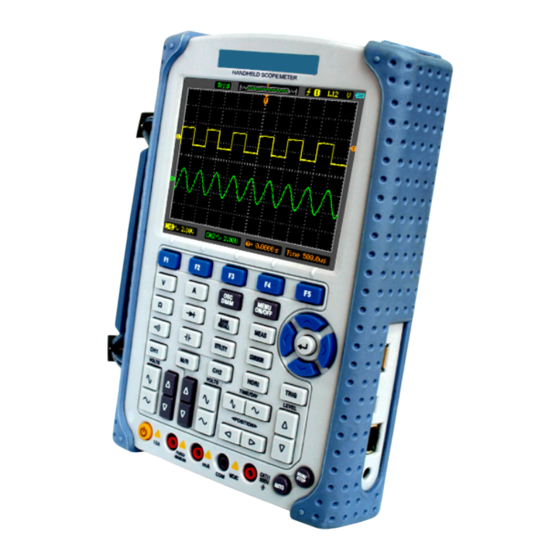
DSO8000 SERIES
HANDHELD SCOPEMETER
USER'S
MANUAL
8060
www.hantek.com
Table of
Contents
Previous
Page
Next
Page
1
2
3
4
5
Advertisement
Table of Contents
Need help?
Do you have a question about the DSO8000 Series and is the answer not in the manual?
Ask a question
Questions and answers
Related Manuals for Hantek DSO8000 Series
Measuring Instruments Hantek DSO3062L User Manual
(89 pages)
Measuring Instruments Hantek DSO3062AL User Manual
(89 pages)
Measuring Instruments Hantek DSO3102 User Manual
Pc based digital oscilloscope (71 pages)
Measuring Instruments Hantek HSA2030 User Manual
Handheld spectrum analyzer hsa2030/hsa2016 series (70 pages)
Measuring Instruments Hantek Hantek2000 Series User Manual
Handheld scopemeter (35 pages)
Measuring Instruments Hantek LA5034 User Manual
(44 pages)
Measuring Instruments Hantek 4032L User Manual
Pc usb logic analyzer (40 pages)
Measuring Instruments Hantek 1832C User Manual
Handheld lcr meter (32 pages)
Measuring Instruments Hantek HTM200 Series User Manual
Multi-channel temperature recorder (58 pages)
Measuring Instruments Hantek CC-650 Operator's Manual
Ac/dc current probe (4 pages)
Measuring Instruments Hantek HT8000 Series Instruction Manual
High voltage isolating probes (13 pages)
Measuring Instruments Hantek HDG3000C Series Quick Manual
Arbitrary waveform signal generator (23 pages)
Measuring Instruments Hantek HT300B Quick Start Manual
Passive probes (2 pages)
Measuring Instruments Hantek CC-800 Operator's Manual
Ac/dc current probe (5 pages)
Measuring Instruments Hantek HDG1000A User Manual
(6 pages)
This manual is also suitable for:
8060
Table of Contents
Print
Rename the bookmark
Delete bookmark?
Delete from my manuals?
Login
Sign In
OR
Sign in with Facebook
Sign in with Google
Upload manual
Upload from disk
Upload from URL


Need help?
Do you have a question about the DSO8000 Series and is the answer not in the manual?
Questions and answers