Table of Contents
Advertisement
Advertisement
Table of Contents

Related Manuals for Hantek Hantek2000 Series


Summary of Contents for Hantek Hantek2000 Series
- Page 1 Hantek2000 Series Handheld Scopemeter User Manual V1.1...
-
Page 2: Copyright Declaration
Hantek reserves all rights to modify this document without prior notice. Please contact Hantek for the latest version of this document before placing an order. Hantek has made every effort to ensure the accuracy of this document but does not guarantee the absence of errors. Moreover, Hantek assumes no responsibility in obtaining permission and authorization of any third party patent, copyright or product involved in relation to the use of this document. -
Page 3: General Safety Summary
General Safety Summary Read the following safety precautions to avoid injury and prevent damage to this product or any products connected to it. To evade potential hazards, use this product only as specified. Only qualified personnel should perform maintenance. Avoid fire or personal injury. Use suitable power cord. -
Page 4: Safety Terms And Symbols
Safety Terms and Symbols Terms on the product. The following terms may appear on the product: Danger It represents that harms may be caused to you at once if you perform the operation. Warning It represents that latent harms may be caused to you if you perform the operation. -
Page 5: Brief Introduction
Brief Introduction This series Scopemeter is compact, portable, and flexible operation; Using color TFTLCD and pop-up menus to display; to achieve its ease of use, greatly improving the user productivity. In addition, this product has superior performance and it is powerful, affordable, high cost. The real-time sampling rate can be as high as 250MSa/S,can meet the market demand of complex signals and capture speed;... -
Page 6: Table Of Contents
Content Copyright Declaration ......................2 General Safety Summary ................... 3 Safety Terms and Symbols ..................4 Product Scrapping ..................... 4 Brief Introduction ....................... 5 Content ..........................6 Getting Started ........................7 Front Panel ........................ 8 The user interface ...................... 9 General Inspection ..................... -
Page 7: Getting Started
Getting Started This oscilloscope is a small, lightweight portable instrument,to provide users with a convenient and easy to operate front panel, you can perform basic tests. Front Panel The user interface General Inspection Functional Check Probe Check... -
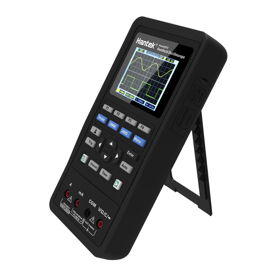
Page 8: Front Panel
Front Panel The following diagram briefly describes the front panel of this series oscilloscope, so that you can be familiar with it in the shortest possible time. -
Page 9: The User Interface
The user interface General Inspection Please check the instrument as following steps after receiving an oscilloscope: Check the shipping container for damage: Keep the damaged shipping container or cushioning material until the contents of the shipment have been checked for completeness and the instrument has been checked mechanically and electrically. -
Page 10: Functional Check
Functional Check Follow the steps below to perform a quick functional check to your oscilloscope. 1. Power Press the power key and the device starts. Press the power key again, and the device will shut down. Before start it, please confirm that the battery has enough power. The oscilloscope is equipped with a power adapter and the interface is Type-C. - Page 11 attenuation in the channel menu to 10X. Set the switch on the probe to 10X and connect the probe to Channel 1 on the oscilloscope. If you use the probe hook-tip, ensure it is firmly inserted onto the probe. Attach the probe tip to the generator output connector (recommended input ~2V@1KHz peak-peak square wave), and connect the reference lead to the ground of the generator.
-
Page 12: Function Introduction
Function Introduction This chapter will introduce the functions of oscilloscope in detail. Menu and Control Keys Connectors Automatically set Default setting Horizontal System Vertical System Trigger System Save Waveform Reference Waveform ... -
Page 13: Menu And Control Keys
Menu and Control Keys All the keys are described as follows: Scope: Oscilloscope mode. DMM:Multimeter mode. AWG:Waveform generator. Menu:Function menu. Trig:Trigger setting menu. Enter: In scope, save the user-defined settings of the oscilloscope; In generator, press the button to confirm after entering the character. Auto: It automatically adjust the horizontal and vertical scales of the oscilloscope automatically and set the trigger coupling, type, position, slope, level and mode, etc., to acquire a stable waveform display. -
Page 14: Connectors
corresponding menu items in the screen. Shortcut keys. Long press this button to enter the menu, and choose shortcut key function; After setting, press this button single time to respond to the corresponding function. In scope, stop or run the waveform acquisition; In DMM, hold the measuring data or update data;... -
Page 15: Default Setting
input signal. Functions Settings Cursor Display Format Set to YT Horizontal Position Adjusted SEC/DIV Adjusted Trigger Level Set to 50% Trigger Mode Auto Trigger Source Adjusted Trigger Slope Adjusted Trigger Type Edge Vertical Bandwidth Full Vertical Coupling VOLTS/DIV Adjusted The Auto function examines all channels for signals and displays corresponding waveforms. -
Page 16: Horizontal System
Measure On or Off Source Slope Rising Trigger (Edge) Mode Auto Level 0.00v Bandwidth Limit Unlimited Coupling Vertical System, Probe Attenuation All Channels Position 0.00div (0.00V) VOLTS/DIV The following settings do not change when you recall default settings. Language Option ... -
Page 17: Vertical System
Automatically enters the scan mode. Vertical System Vertical system can be used to adjust the vertical scale and location and other settings of the channel. Each channel has a separate vertical menu, and each channel can be set separately. 1. Vertical Position Press Channel->F1 to select the channel, and press Up or Down direction keys to move the vertical position of the selected channel. -
Page 18: Save Waveform
Trigger Source: Select the trigger source signal to CH1 or CH2. You can use the trigger source options to select the signal that the oscilloscope uses as a trigger. Trigger Mode: You can select the Auto or Normal mode to define how the oscilloscope acquires data when it does not detect a trigger condition. -
Page 19: Reference Waveform
2. users can permanently store 6 waveforms in the oscilloscope memory and rewrite them at any time. Reference Waveform The REF channel is used to display the reference waveform, which can compare the actual waveforms with the reference waveforms so as to find out the differences. Press Menu button to enter, and select Ref to enter reference Waveform menu. - Page 20 measurement, make sure that the measured source is the signal you need to measure. Press Menu button to enter, and select Cursor to enter cursor measurement. Cursor Measurement Menu Table Menu Setting Description Open the cursor measurement. Enable Close the cursor measurement. The horizontal line is shown to measure the voltage Voltage parameters.
-
Page 21: Utility
Utility Press Menu button to enter. Utility Menu Table Menu Setting Description 中文 Language Set the menu language. English Open the key sound. Sound Close the key sound. Backlight 1~10 Set backlight brightness of the screen. luminance Backlight Set the screen backlight time. time 120s Unlimited... - Page 22 boot button at the same time. The backlight of the button will jump between red and green, that is, enter the upgrade mode. Using the Dfu download tool to download the program, the oscilloscope power off, and then re-energize. Shortcut key Long press button to enter shortcut key settings menu, and choose shortcut key function;...
-
Page 23: Dmm
This chapter introduces the multimeter function. Interface The measuring types include DC voltage (V, mV), AC voltage, DC current (A, mA), AC current (A, mA), resistance, capacitance, diode, and on-off test. Measurement 1. DC and AC voltage measurement a) Press the power button to turn on, then press the "DMM" button to enter to the multimeter function interface;... - Page 24 a) Press the power button to turn on, then press the "DMM" button to enter to the multimeter function interface; b) To measure the DC current greater than 200mA, press the up, down, left and right keys or F1, F2, F3, F4 multi function keys to select "DC A" or "AC A", and insert the black pen to the input end of the COM banana socket, and insert the red pen into the input port of the “A”...
- Page 25 m) Press the power button to turn on, then press the "DMM" button to enter to the multimeter function interface; n) Press the up, down, left and right direction keys or F1, F2, F3, F4 multi-function keys to select " ";...
-
Page 26: Generator
Generator This chapter introduces the function of waveform generator. Interface Operation description Press the power button to turn on, then press the "AWG" button to enter the waveform generator function interface. 1. Set type Press F1 button to select the desired signal waveform, the optional waveform type includes square, triangle, sine, trapezoidal and four arbitrary. - Page 27 select "OK" and press "Enter" button to confirm. 4. Set offset Press F4 button to enter the second page. Press F2 to select Offset, then use the up, down, left and right direction keys to adjust the frequency, press F2 button to open the digital keyboard again, use the up, down, left, right direction keys and "Enter"...
- Page 28 The waveform observed by an oscilloscope is as follows:...
-
Page 29: Troubleshooting
6) In addition, you may press the Auto button to perform an automatic detection of signals at first. 7) Contact HANTEK Technical Support department in time if there is still no display of waveforms. 3. If the waveform of the input signal is distorted seriously, follow these steps: 1)... -
Page 30: General Care And Cleaning
General Care and Cleaning General Care Do not put or leave the device in a place where the LCD display will be exposed to direct sunlight for long periods of time. Note: To avoid damage to the oscilloscope or probes, do not expose them to sprays, liquids, or solvents. -
Page 31: Appendix A: Technical Specifications
Appendix A: Technical Specifications All specifications herein mentioned apply to the series oscilloscopes. Before checking an oscilloscope to see if it complies with these specifications, make sure it meets the following conditions: The oscilloscope must have been operating continuously for twenty minutes under the specified operating temperature. - Page 32 Mode Auto, Normal, single Level ± 4 divisions from center of screen Trigger Level Accuracy 0.2div × volts/div within ±4 divisions from center of screen Slope Rising, Falling, Rising & Falling Source CH1, CH2 Input Coupling DC, AC or GND Input Impedance, 25pF±...
- Page 33 Mechanical Dimension 199 x 98x 40mm (L x W x H) Weight 624g Arbitrary Waveform Generator (Hantek2D72/Hantek2D42) Sine: 1Hz~25MHz Square: 1Hz~10MHz Waveform Frequency Ramp: 1Hz~1MHz EXP: 1Hz~5MHz Sampling 250MSa/s 2.5Vpp(50Ω) Amplitude 5Vpp(High impedance) Frequency Resolution 0.10% Channel 1CH waveform output Waveform Depth 512Sa Vertical Resolution...
- Page 34 400mV: 250V, other: 600Vrms. 4.000V ± (1.2% + 5) 40.00V 10mV 400.0V 100mV AC Voltage ± (1.5% + 5) 600.0V Frequency: 40Hz~400Hz; Frequency of 400V and 600V: 40Hz~100Hz ± (1% + 2) 40.00mA 10uA ± (1.5% + 2) 200.0mA 100uA ±...
-
Page 35: Appendix B: Accessories
Appendix B: Accessories All the following accessories are available by contacting your local HANTEK distributor. Standard Accessories • Probe×1 (1.5m), 1:1, (10:1) Passive Probes • A Power adapter • A USB Line • Crocodile clip line *1 (For Hantek2C42/Hantek2C72) •...
Need help?
Do you have a question about the Hantek2000 Series and is the answer not in the manual?
Questions and answers