Table of Contents
Advertisement
TM
Table of Contents
Section Code
Section
1
1
1
Reading the Product Specification Label
1
1
1
Leveling the Machne
1
Moving the Machine
1
1
1
1
1
Mechanical Procedures
2
Belt Tension Adjustment
3
Set the Brake Tension (Calibration)
Part Replacement
4
5
6
Crank Arms - 170
7
Transport Wheels
8
9
Handlebar Assembly
10
Console Mast
11
Data Cable in the Mast
12
13
14
Drive Belt and Flywheel Assembly
15
16
Drive Pulley Assembly (Crank Assembly) - 130
17
RPM Sensor (Speed Sensor)
18
Nautilus, Inc., (800) NAUTILUS / (800) 628-8458, www.NautilusInc.com - Customer Service: North America (800) 605-3369, csnls@nautilus.com | outside U.S. www.nautilusinternational.com |
© 2013 Nautilus, Inc. | Schwinn is a trademark licensed to Nautilus, Inc., which is registered or otherwise protected by common law in the United States and other countries. Polar
trademark of its owner.
ORIGINAL MANUAL - ENGLISH VERSION ONLY
8018282.070119.B
™
Schwinn
130, 170 (Model Year 2013), Journey 1.0 and
Journey 1.5 (Model Year 2013) Upright Bikes Service Manual
Page Number
2
3
3
3
4
5
5
5
6
8
10
12
13
16
19
21
23
27
29
34
37
41
44
46
50
53
55
59
60
1
Service Manual
8006483.070119.F
®
is a
Advertisement
Table of Contents

Subscribe to Our Youtube Channel
Related Manuals for Schwinn Journey 1.0


Summary of Contents for Schwinn Journey 1.0
-
Page 1: Table Of Contents
Nautilus, Inc., (800) NAUTILUS / (800) 628-8458, www.NautilusInc.com - Customer Service: North America (800) 605-3369, csnls@nautilus.com | outside U.S. www.nautilusinternational.com | © 2013 Nautilus, Inc. | Schwinn is a trademark licensed to Nautilus, Inc., which is registered or otherwise protected by common law in the United States and other countries. Polar ®... -
Page 2: Important Safety Instructions
Nautilus, Inc., (800) NAUTILUS / (800) 628-8458, www.NautilusInc.com - Customer Service: North America (800) 605-3369, csnls@nautilus.com | outside U.S. www.nautilusinternational.com | © 2013 Nautilus, Inc. | Schwinn is a trademark licensed to Nautilus, Inc., which is registered or otherwise protected by common law in the United States and other countries. Polar is a trademark of its owner. -
Page 3: Safety Warning Labels And Serial Number
Safety Warning Labels and Serial Numbers WARNING! • Injury or death is possible if caution is not used while using this machine. • Keep children and pets away. • Read and follow all warnings on this machine. • Refer to the Owner’s Manual for additional warnings and safety Serial number information. -
Page 4: Maintenance
FCC Compliance Changes or modifications to this unit not expressly approved by the party responsible for compliance could void the user’s authority to operate the equipment. The machine and power supply comply with part 15 of the FCC rules. Operation is subject to the following two conditions: (1) This device may not cause harmful interference, and (2) this device must accept any interference received, including interference that may cause undesired operation. -
Page 5: Usb Charging
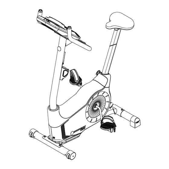
Leveling the Bike Levelers are found on each side of the Rear Stabilizer. Turn the knob to adjust the stabilizer foot. Make sure the bike is level and stable before you exercise. Moving the Bike To move the upright bike, carefully tilt the Handlebars toward you while pushing the front of the bike downward. Push the bike to the desired location. -
Page 6: Troubleshooting
Troubleshooting Condition/Problem Things to Check Solution No display/partial display/ Check electrical (wall) Make sure unit is plugged into a functioning wall outlet. unit will not turn on outlet Check connection at front Connection should be secure and undamaged. Replace adapter of unit or connection at unit if either are damaged. - Page 7 Condition/Problem Things to Check Solution Check magnet position Magnet should be in place on pulley. (requires shroud removal) Check Speed Sensor Speed sensor should be aligned with magnet and connected to (requires shroud removal) data cable. Realign sensor if necessary. Replace if there is any damage to the sensor or the connecting wire.
-
Page 8: Console Service Mode
Console Service Mode – x30 / x70 series (MY13) and x30 (MY16) Consoles The Console Setup Mode lets you input the date and time, set the units of measurement to either English or Metric, change the machine type, control the sound settings ( on/ off), or see maintenance statistics (Total Run Hours – for service technician use only). - Page 9 g. RUN LED TEST – Drives LEDs to the following states: All LEDs On 1 second All LEDs Off 1 second Sequence Segments 1 at a time – on 1 second, off 1 second Press any key to exit test h.
-
Page 10: Maintenance Parts Exploded View
Maintenance Parts Exploded View Your machine may differ. Use only as a guide. Console HR Cables Flywheel Console Mast CHR Sensors Brake Assembly Pedals Seat RPM Sensor Crank Arms Seat Post w/ Slider Speed Sensor Magnet Left Shroud Adjustment Knob Servo Motor Power Inlet Seat Post Shroud... - Page 11 Console HR Cables Flywheel Console Mast CHR Sensors Brake Assembly Pedals Seat RPM Sensor Crank Arms Seat Post w/ Slider Speed Sensor Magnet Left Shroud Adjustment Knob Servo Motor Power Inlet Seat Post Shroud Drive Belt Right Shroud Water Bottle Holder Drive Pulley Top Shroud Rear Stabilizer...
-
Page 12: Replacement Procedure Skill Level
REPLACEMENT PROCEDURE SKILL LEVEL Level I : Low - very little mechanical knowledge or exposure. Level II : Intermediate - some experience with mechanical procedures Level III : Advanced - knowledgeable about mechanical procedures Disconnect all power to the machine before you service it. When disposing of old parts, obey the applicable local and provincial requirements. - Page 13 ORIGINAL DOCUMENT - ENGLISH VERSION ONLY Schwinn is a trademark licensed to Nautilus, Inc., which is registered or otherwise protected by common law in the United States and other countries. | Important Safety Instructions - Before servicing or using this equipment, obey the following warnings: This icon means a potentially hazardous situation which, if not avoided, could result in death or serious injury.
- Page 14 NOTICE: It is necessary to remove the Shrouds for this procedure. Refer to the “Replace the Shrouds” procedure. Disconnect all power to the machine before you service it. Note: Your machine may not match the image. For reference only. Figure 1 Remove the Top Shroud, Left Shroud and Right Shroud from the Main Unit.
- Page 15 Reassembly is the reverse procedure. NOTICE: Be sure not to crimp any cables. 130/230 bikes—To reinstall the Pedals, carefully align the threads and hand tighten to prevent cross-threading. Then tighten fully with pedal wrench. Note: The Left Pedal is reverse-threaded. Orientation is based from a seated position on the bike.
- Page 16 ORIGINAL DOCUMENT - ENGLISH VERSION ONLY Schwinn is a trademark licensed to Nautilus, Inc., which is registered or otherwise protected by common law in the United States and other countries. | Important Safety Instructions - Before servicing or using this equipment, obey the following warnings: This icon means a potentially hazardous situation which, if not avoided, could result in death or serious injury.
- Page 17 NOTICE: It is necessary to remove the shrouds for this procedure. Refer to the “Replace the Shrouds” procedure. Note: Your machine may not match the image. For reference only. Disconnect and reconnect the AC Adapter from the wall outlet to turn the power off and on. Push QuickStart and verify that the console shows that the default resistance level is 4.
- Page 18 To adjust the Brake tension, loosen the 2 hex head bolts (C) and move the Servo Motor assembly (D) until the closest point on the Brake Magnet (A) is within 3.0 mm (1/8”) of the Flywheel (B). Tighten the bolts. Note: If the cardboard is not 3mm (1/8”) thick, you can use the pages of a paperback book to measure the gap.
- Page 19 ORIGINAL DOCUMENT - ENGLISH VERSION ONLY Schwinn is a trademark licensed to Nautilus, Inc., which is registered or otherwise protected by common law in the United States and other countries. | Important Safety Instructions - Before servicing or using this equipment, obey the following warnings: This icon means a potentially hazardous situation which, if not avoided, could result in death or serious injury.
-
Page 20: Console
Disconnect all power to the machine before you service it. Note: Your machine may not match the image. For reference only. 130 / 170 1. Remove screws that attach Console to the Mast. Carefully lift the Console off the Mast. 2. - Page 21 ORIGINAL DOCUMENT - ENGLISH VERSION ONLY Schwinn is a trademark licensed to Nautilus, Inc., which is registered or otherwise protected by common law in the United States and other countries. | Important Safety Instructions - Before servicing or using this equipment, obey the following warnings: This icon means a potentially hazardous situation which, if not avoided, could result in death or serious injury.
-
Page 22: Pedals
Note: Your machine may not match the image. For reference only. Loosen and remove the old Pedals. Discard the old Pedals. Note: The Left Pedal is reverse-threaded. Orientation is based from a seated position on the bike. The Left Pedal has an “L”, the Right Pedal an “R”. - Page 23 ORIGINAL DOCUMENT - ENGLISH VERSION ONLY Schwinn is a trademark licensed to Nautilus, Inc., which is registered or otherwise protected by common law in the United States and other countries. | Important Safety Instructions - Before servicing or using this equipment, obey the following warnings: This icon means a potentially hazardous situation which, if not avoided, could result in death or serious injury.
- Page 24 Note: Your machine may not match the image. For reference only. Loosen and remove the old Pedals. Set them safely aside for reassembly. Note: The Left Pedal is reverse-threaded. Orientation is based from a seated position on the bike. The Left Pedal has an “L”, the Right Pedal an “R”.
- Page 25 Thread the Crank Puller into the Crank Arm (B). When the Crank Puller is in the correct position, only 1-2 threads on the outer portion (CP2) of the Crank Puller should show. Note: Be sure the end of the Bolt (CP1) of the Crank Puller is flush with the Nut (CP2) as shown, before use.
- Page 26 Installation is the reverse procedure. Installation does not require the use of the crank puller. To reinstall the Pedals, carefully align the threads and hand tighten to prevent cross-threading. Then tighten fully with pedal wrench. Note: The Left Pedal is reverse-threaded. Be sure to attach Pedals on the correct side of the Bike.
- Page 27 ORIGINAL DOCUMENT - ENGLISH VERSION ONLY Schwinn is a trademark licensed to Nautilus, Inc., which is registered or otherwise protected by common law in the United States and other countries. | Important Safety Instructions - Before servicing or using this equipment, obey the following warnings: This icon means a potentially hazardous situation which, if not avoided, could result in death or serious injury.
- Page 28 Note: Your machine may not match the image. For reference only. Loosen and remove the screw (A) from the old Transport Wheel assembly (B), and set it safely aside for reassembly. Remove the old Transport Wheel assembly from the front stabilizer (C), and discard.
- Page 29 ORIGINAL DOCUMENT - ENGLISH VERSION ONLY Schwinn is a trademark licensed to Nautilus, Inc., which is registered or otherwise protected by common law in the United States and other countries. | Important Safety Instructions - Before servicing or using this equipment, obey the following warnings: This icon means a potentially hazardous situation which, if not avoided, could result in death or serious injury.
- Page 30 Disconnect all power to the machine before you service it. Note: Your machine may not match the image. For reference only. Remove the Seat Post and the Seat Adjustment Knob (A). Set them safely aside for reassembly. Remove the Seat Post Shroud and set it safely aside for reassembly.
- Page 31 Loosen and remove the Pedals. Set them safely aside for reassembly. Note: The Left Pedal is reverse-threaded. Orientation is based from a seated position on the bike. The Left Pedal has an “L”, the Right Pedal an “R”. Remove the Mast Gasket. Set it safely aside for reassembly. Bend the edges of the Top Shroud to disengage the inside tabs from the Main Assembly, and slide the Top Shroud up the Mast.
- Page 32 11. Using a #2 Phillips Screwdriver, remove the 6 screws (indicated) that secure the Left Shroud. Remove the bottom screws first. and then the top screws. Slowly remove the Left Shroud. Note: Find the Power Inlet (E) in the Left Shroud. Disconnect the Power Inlet cable (E1) from the wiring harness (F).
- Page 33 12. Using a #2 Phillips Screwdriver, remove the 4 screws that secure the Right Shroud. Remove the bottom screws first. and then the top screws. Slowly remove the Right Shroud. 13. Installation is the reverse procedure. Put the Left Shroud in postion first to align the screws for the Right Shroud.
- Page 34 ORIGINAL DOCUMENT - ENGLISH VERSION ONLY Schwinn is a trademark licensed to Nautilus, Inc., which is registered or otherwise protected by common law in the United States and other countries. | Important Safety Instructions - Before servicing or using this equipment, obey the following warnings: This icon means a potentially hazardous situation which, if not avoided, could result in death or serious injury.
- Page 35 Disconnect all power to the machine before you service it. Note: Your machine may not match the image. For reference only. Remove screws that attach Console to the Mast. Carefully lift the Console off the Mast. Disconnect the Data Cable and Heart Rate Cable from the back of the Console.
- Page 36 Remove the T-handle and washers that attach the Handlebar to the Mast. Set them safely aside for reassembly. NOTICE: Hold the Handlebar so that it does not fall. Untie the string from the HR Cable. Remove the old Handlebar and discard it. Put the replacement Handlebar in the bracket, adjust the Handlebar to the desired angle, and install the T-handle through the holes.
- Page 37 ORIGINAL DOCUMENT - ENGLISH VERSION ONLY Schwinn is a trademark licensed to Nautilus, Inc., which is registered or otherwise protected by common law in the United States and other countries. | Important Safety Instructions - Before servicing or using this equipment, obey the following warnings: This icon means a potentially hazardous situation which, if not avoided, could result in death or serious injury.
- Page 38 Disconnect all power to the machine before you service it. Note: Your machine may not match the image. For reference only. Remove screws that attach Console to the Mast. Carefully lift the Console off the Mast. Disconnect the Data Cable and Heart Rate Cable from the back of the Console.
- Page 39 Remove the T-handle and washers that attach the Handlebar to the Mast. Set them safely aside for reassembly. NOTICE: Hold the Handlebar so that it does not fall. Remove the Handlebar and set it safely aside for reassembly. Bend the edges of the Top Shroud to disengage the inside tabs from the Main Assembly, and slide the Mast Gasket and Top Shroud up the Mast.
- Page 40 10. Put the Handlebar in the bracket, adjust the Handlebar to the desired angle, and install the T-handle through the holes and washers. NOTICE: Do not crimp the cables. 11. Use the pull cable in the Handlebar Bracket to route the HR cable through the slot under the Handlebar Bracket to the top of the mast.
- Page 41 ORIGINAL DOCUMENT - ENGLISH VERSION ONLY Schwinn is a trademark licensed to Nautilus, Inc., which is registered or otherwise protected by common law in the United States and other countries. | Important Safety Instructions - Before servicing or using this equipment, obey the following warnings: This icon means a potentially hazardous situation which, if not avoided, could result in death or serious injury.
- Page 42 Disconnect all power to the machine before you service it. Note: Your machine may not match the image. For reference only. Remove screws that attach Console to the Mast. Carefully lift the Console off the Mast. Disconnect the Data Cable and Heart Rate Cable from the back of the Console.
- Page 43 Tie the length of string to the end (A) of the Data Cable at the base of the Mast. Hold the other end of the Data Cable (B) and carefully pull it out of the Mast so that the string extends through the length of the Mast.
- Page 44 ORIGINAL DOCUMENT - ENGLISH VERSION ONLY Schwinn is a trademark licensed to Nautilus, Inc., which is registered or otherwise protected by common law in the United States and other countries. | Important Safety Instructions - Before servicing or using this equipment, obey the following warnings: This icon means a potentially hazardous situation which, if not avoided, could result in death or serious injury.
-
Page 45: Shrouds
NOTICE: It is necessary to remove the Shrouds for this procedure. Refer to the “Replace the Shrouds” procedure. It may be necessary to adjust the Brake tension at the end of this procedure. Refer to the “Set the Brake Tension” procedure. Disconnect all power to the machine before you service it. - Page 46 ORIGINAL DOCUMENT - ENGLISH VERSION ONLY Schwinn is a trademark licensed to Nautilus, Inc., which is registered or otherwise protected by common law in the United States and other countries. | Important Safety Instructions - Before servicing or using this equipment, obey the following warnings: This icon means a potentially hazardous situation which, if not avoided, could result in death or serious injury.
- Page 47 NOTICE: It is necessary to remove the Shrouds for this procedure. Refer to the “Replace the Shrouds” procedure. It may be necessary to adjust the Brake tension at the end of this procedure. Refer to the “Set the Brake Tension” procedure. Disconnect all power to the machine before you service it.
-
Page 48: Servo Motor
Disconnect the Speed Sensor Cable (D) and Power Inlet Cable (E) from the wiring harness (F). Tie the length of string to the end of the lower Console Cable (G) at the top of the Mast mount. Pull the cable and string down through the hole (H) at the base of the Mast so that the string extends through the mast. - Page 49 13. Reinstall the Mast, Console and Top Shroud. (Refer to the “Replace the Shrouds” procedure.) Turn the power on. Machine is on. Current is active. There is risk of electrical shock. 14. Use the console to set the resistance to the highest level. Unplug the machine.
- Page 50 ORIGINAL DOCUMENT - ENGLISH VERSION ONLY Schwinn is a trademark licensed to Nautilus, Inc., which is registered or otherwise protected by common law in the United States and other countries. | Important Safety Instructions - Before servicing or using this equipment, obey the following warnings: This icon means a potentially hazardous situation which, if not avoided, could result in death or serious injury.
- Page 51 NOTICE: It is necessary to remove the Shrouds for this procedure. Refer to the “Replace the Shrouds” procedure. It is necessary to adjust the Drive Belt tension at the end of this procedure. Refer to the “Belt Tension Adjustment” procedure Disconnect all power to the machine before you service it.
- Page 52 Using needlenose pliers, carefully release the spring (E1) on the Belt Tensioner (E). To remove the hardware from the Flywheel (C), use the 15 mm open end wrench to hold the nut (F) on one side steady and remove the nut on the opposite side with the 15 mm socket and wrench. Set the hardware safely aside.
- Page 53 ORIGINAL DOCUMENT - ENGLISH VERSION ONLY Schwinn is a trademark licensed to Nautilus, Inc., which is registered or otherwise protected by common law in the United States and other countries. | Important Safety Instructions - Before servicing or using this equipment, obey the following warnings: This icon means a potentially hazardous situation which, if not avoided, could result in death or serious injury.
-
Page 54: Belt Tensioner Assembly (Idler Assembly)
NOTICE: It is necessary to remove the Shrouds for this procedure. Refer to the “Replace the Shrouds” procedure. It is necessary to adjust the Drive Belt tension at the end of this procedure. Refer to the “Belt Tension Adjustment” procedure Disconnect all power to the machine before you service it. - Page 55 ORIGINAL DOCUMENT - ENGLISH VERSION ONLY Schwinn is a trademark licensed to Nautilus, Inc., which is registered or otherwise protected by common law in the United States and other countries. | Important Safety Instructions - Before servicing or using this equipment, obey the following warnings: This icon means a potentially hazardous situation which, if not avoided, could result in death or serious injury.
- Page 56 NOTICE: It is necessary to remove the Shrouds for this procedure. Refer to the “Replace the Shrouds” procedure. It is necessary to adjust the Drive Belt tension at the end of this procedure. Refer to the “Belt Tension Adjustment” procedure Disconnect all power to the machine before you service it.
- Page 57 Carefully pull the Pulley Shaft Assembly (H) until it works out of the Frame and releases the Washer (J), Bumper (K), Bearings (L) and Bearing Brackets (M). Installation is the reverse procedure. NOTICE: Do not overtighten the crank hardware as this can damage the bearings.
- Page 58 ORIGINAL DOCUMENT - ENGLISH VERSION ONLY Schwinn is a trademark licensed to Nautilus, Inc., which is registered or otherwise protected by common law in the United States and other countries. | Important Safety Instructions - Before servicing or using this equipment, obey the following warnings: This icon means a potentially hazardous situation which, if not avoided, could result in death or serious injury.
- Page 59 NOTICE: It is necessary to remove the Shrouds for this procedure. Refer to the “Replace the Shrouds” procedure. Disconnect all power to the machine before you service it. Note: Your machine may not match the image. For reference only. Carefully remove the Shrouds. Refer to the “Replace the Upright bike Shrouds”...
- Page 60 ORIGINAL DOCUMENT - ENGLISH VERSION ONLY Schwinn is a trademark licensed to Nautilus, Inc., which is registered or otherwise protected by common law in the United States and other countries. | Important Safety Instructions - Before servicing or using this equipment, obey the following warnings: This icon means a potentially hazardous situation which, if not avoided, could result in death or serious injury.
- Page 61 NOTICE: It is necessary to remove the Shrouds for this procedure. Refer to the “Replace the Shrouds” procedure. Disconnect all power to the machine before you service it. Note: Your machine may not match the image. For reference only. Carefully remove the Left Shroud. Refer to the “Replace the Shrouds”...
-
Page 62: Power Inlet
Loosen and remove the thin Nut from the Power Inlet (C) on the outside of the Shroud. Pull the Power Inlet plug (C) out of the hole toward the inside of the Shroud. Discard the old Power Inlet assembly. Installation is the reverse procedure. NOTICE: Do not crimp any cables.
Need help?
Do you have a question about the Journey 1.0 and is the answer not in the manual?
Questions and answers
I do not have a manual for the Schwinn Stationary Bike Journey 1.0 and only want fitness settings
To find the fitness settings for the Schwinn Stationary Bike Journey 1.0, use the Console Service Mode. This mode is listed in the service manual under "Console Service Mode" on page 8. Accessing this mode allows you to view and adjust internal settings related to the bike’s performance.
This answer is automatically generated
How do I setup the fitness settings and only fitness settings for the Schwinn Stationary Bike Journey 1.0
To set up the fitness settings on the Schwinn Journey 1.0 stationary bike:
1. Enter the Console display menu.
2. The Machine Type prompt will appear (only on x30 series consoles).
3. Use the Increase/Decrease buttons to choose between “BIKE” and “ELIP” (elliptical).
4. Press OK to confirm your selection.
5. The console will return to the Power-Up / Idle Mode screen.
For further adjustments, use the “Console Service Mode” as described in the manual.
This answer is automatically generated