
Subscribe to Our Youtube Channel
Related Manuals for Life Fitness INA-CST


Summary of Contents for Life Fitness INA-CST
- Page 1 Life Fitness Arc Trainer (INA-CST, INA-LS4, INA-TS4, INA-CS, INA-LSL, INA-TSL, INATTS, INATLS, PFA-ARC-LB-11, PFT-ARC-TB-11, PF-INA-LBSL-ALLXM-11, PF-INA-TBSL- ALLXM-11) Assembly Instructions 1015939-0001 REV AD...
- Page 3 Latin America and Caribbean* Spain Hong Kong Life Fitness, LLC Life Fitness IBERIA Life Fitness Asia Pacific LTD 10601 W Belmont Ave C/Frederic Mompou 5,1º1ª 26/F, Global Trade Square Franklin Park, IL 60131 U.S.A. 08960 Sant Just Desvern Barcelona...
-
Page 4: Table Of Contents
Copyright 2022, Life Fitness, LLC. All Rights Reserved. Life Fitness, Hammer Strength, Cybex, ICG and SCIFIT are registered trademarks of Life Fitness, LLC and its affiliated companies and subsidiaries. Disclaimer: Images and specifications are current as of the date of publication and are subject to change. -
Page 5: Getting Started
• Life Fitness Family of Brands does not warrant nor guarantee that component parts used in the manufacture of products offered under the Life Fitness Family of Brands are latex-free. Users of these products must take all necessary precautions to prevent accidental contact that could lead to an adverse latex reaction. - Page 6 • Position the product so that the power cord plug to the wall is accessible to the user. Make sure that the power cord is not knotted or twisted and that it is not trapped under any equipment or other objects. •...
-
Page 7: Consignes De Sécurité
Consignes de Sécurité Veuillez lire toutes les instructions avant usage. Prêtez une attention toute particulière aux instructions de sécurité ci-dessous avant de choisir un emplacement et de commencer à assembler votre produit. AVERTISSEMENT : Une utilisation incorrecte ou excessive de l'appareil peut entraîner des blessures. Life Fitness Family of Brands Recommande VIVEMENT aux utilisateurs de passer un examen médical complet avant d'entamer un programme d'entraînement, et tout particulièrement dans les cas suivants : antécédents familiaux d'hypertension (pression sanguine trop élevée) ou de pathologies cardiaques, utilisateurs de 45 ans... - Page 8 à la clientèle. Nous vous en fournirons de nouvelles. Les étiquettes d’avertissement sont expédiées avec les appareils et doivent être installées avant utilisation de ces derniers. Life Fitness Family of Brands n’est pas responsable des étiquettes manquantes ou endommagées.
-
Page 9: Setup
Setup Read the entire manual before setting up the unit. Choosing and Preparing Site Before assembling the unit, verify the chosen site meets the following criteria: • Area is well lit and well ventilated. • Surface is structurally sound and properly leveled. •... -
Page 10: Electrical Power Requirements (Applicable For Units Using External Power Supply)
Electrical Power Requirements (Applicable for Units Using External Power Supply) • Units that are equipped with the Integrity SL console are self powered. • Units with Integrity SL console can be used with an optional attachable TV. Use of an attachable TV requires an external power supply. -
Page 11: Check For Console Power - Integrity Sl
Cable TV Hook Up The console can receive both analog and digital signals. LIFE FITNESS is not responsible for the installation of CATV service or components required for the delivery of CATV service. An external TV signal input via a 75-ohm coaxial cable must be present before TV setup can occur. -
Page 12: Product Overview
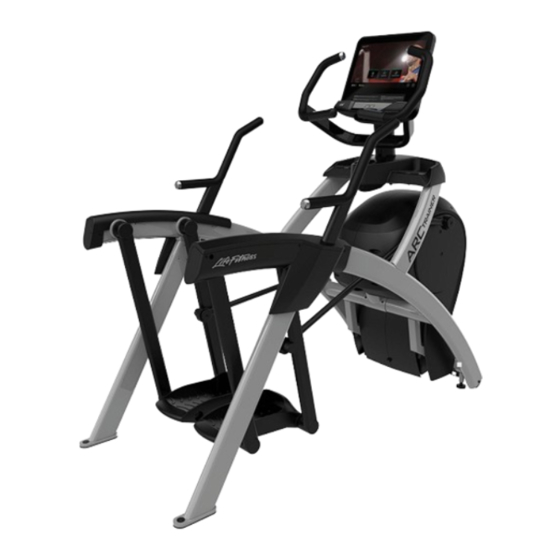
2. Product Overview Product Features Lower Body Item Description Console Accessory Trays Contact Heart Rate Sensors Cup Holder Side Handles Leg Levelers Total Body Item Description Console Accessory Trays Cup Holder Contact Heart Rate Sensors Side Handles Leg Levelers Mounting and Dismounting the Arc Trainer To mount, step one foot at a time atop each of the foot plates. -
Page 13: How To Use The Arc Trainer
To dismount, slowly bring the pedals to a stop. Grasp the stationary handles or part of the frame to assist in stepping off the foot plate, back and away from the machine. When stepping back, ensure that you are beyond and behind the path of motion of the foot plates. -
Page 14: Assembly
3. Assembly Packing and Shipping Options ATTENTION: This product has two packaging and shipping options: Single box or multiple boxes. Both options have the console weldment mounted in a horizontal position for shipping. For single box options, The console, console weldment, and cables are fully assembled. Follow the full assembly procedure but skip the console assembly steps. - Page 15 Hardware Item Description Quantity 7/32” Allen Wrench Grommet, Nylon, Long Grommet, Nylon, Short Screw, Pan Head Phillips, Tap 10-12 x 2" Screw, Pan Head Phillips, M4.2 x 0.7 x 19 Screw, Pan Head Phillips, 6 x .50” Screw, Pan Head Phillips, 8-16 x .50” Screw, Pan Head Phillips, 10-24 x .75"...
- Page 16 NOTE: *Console assembled in Single Box Option. Hardware Pack 1 Hardware Pack 2 Page 14 of 51...
- Page 17 Tools Required • Phillips screwdriver • 7 mm Allen wrench • 1/2” Open end wrench • Stubby Phillips screwdriver • 7/32” Allen wrench • 9/16” Open end wrench • 6 mm Allen wrench • 17 mm Open end wrench Lift and Move Unit 1.
- Page 18 Note for Single Box Option Skip console steps and continue assembly at Install Accessory Tray Base step. Base to Console Cable Connections Plug the console cables into the console. Integrity SL Console Item Description CSAFE Base Switches, Lifepulse Base Power Base Comm TV (optional) Discover SE4 Console...
- Page 19 Attach Console and Console Back Cover - Integrity SL 1. Insert grommets into console weldment. 2. Attach console. Press back cover into spring tab holes of console weldment. Secure back cover to console weldment. NOTE: Do not pinch cables while lowering the console. Integrity SL Item Description...
- Page 20 Attach Console and Console Back Cover - Discover SE4 1. Insert grommets into console weldment. Item Description Weldment, Console Grommet, Nylon, Short 2. Place console into position on console weldment. NOTE: Do not pinch cables while lowering the console. NOTE: Do not install the screw in the location shown (next to arrow) if the Discover SE4 console has a Set Top Box Sync (STB) receiver! The screw will hit the STB receiver inside of the console.
- Page 21 3. Press back cover into spring tab holes of console weldment. Item Description Console Assembly Spring Tab Holes Cover, Console Back Screw, Pan Head Phillips, M4.2 x 0.7 x 19 1.5 Nm (1.1 ft. lbs.) 4. Install screws securing back cover to console assembly using a Phillips Screwdriver. Page 19 of 51...
- Page 22 Attach Console and Console Back Cover - Discover SE3HD / ST 1. Insert grommets into console weldment. 2. Attach console. Press back cover into spring tab holes of console weldment. Secure back cover to console weldment. NOTE: The ground wire is connected to the console weldment.
- Page 23 Install Console Cables to Base (Basic Cabling) This procedure applies to the Basic Cabling option. 1. Plug upper display cable into lower display cable. Item Description Cable, Coax (previously routed to console) Cable, Console to Base Power Cable, Heart Rate and Keypad Switches Cable, Base Signal 2.
- Page 24 Install Accessory Tray Base Install screws securing accessory tray base to frame using a Phillips screwdriver. Item Description Accessory Tray Base Frame Screw, Pan Head Phillips, Tap 10-12 x 2" Install Accessory Tray Top Install screws securing accessory tray top to accessory tray base using a stubby Phillips screwdriver. Item Description Qty.
- Page 25 3. Install screw securing the accessory tray bottom to the frame using a Phillips screwdriver. Item Description Qty. Accessory Tray Bottom Accessory Tray Top Screw, Pan Head Phillips, 6 x .50" Screw, Pan Head Phillips, 8-16 x .50" Install Side Handles 1.
- Page 26 4. Install grommets to left top rear cover. Item Description Grommet, Nylon, Short Cover, Rear, Top, Left 5. Install screws into grommets securing left lower rear cover to left top rear cover using a Phillips screwdriver. Item Description Screw, Pan Head Phillips, M4.2 x 0.7 x 19 Screw, Pan Head Phillips, 10-24 x .75"...
- Page 27 Install Foot Pads Have one person lift the unit while a second person places a foot pad under each of the two back feet. Item Description Foot Pads NOTE: Foot pads need to be installed to prevent rocking. Visually Inspect Unit 1.
- Page 28 3. Grasp the other rear cover and slowly lift the rear foot off the floor. Lower rear foot to the floor. Make note of either rear foot lifting off the floor easier than the other. If both rear feet lift off the floor evenly, secure both leveling foot jam nuts against the frame post using a 9/16” open-end wrench.
-
Page 29: Assembly Procedure - Total Body
Assembly Procedure - Total Body Two people will be required for this procedure. TIP: Read and understand all instructions thoroughly before assembling this unit. Check all items carefully. If there is damage, see the Customer Service section of this manual for proper procedure to return, replace, or reorder parts. The words "left"... - Page 30 Hardware Item Description Quantity 3/16” Allen Wrench 7/32” Allen Wrench Flange Spacer Washer, Flat, .281 ID x .500 OD x .062” Grommet, Nylon, Long Grommet, Nylon, Short Screw, Pan Head Phillips, Tap 10-12 x 2" Screw, Pan Head Phillips, M4.2 x 0.7 x 19 Screw, Pan Head Phillips, 6 x .50”...
- Page 31 NOTE: *Console assembled in Single Box Option. Hardware Pack 1 Hardware Pack 2 Page 29 of 51...
- Page 32 Tools Required • Phillips screwdriver • 7 mm Allen wrench • 17 mm Open end wrench • Stubby Phillips screwdriver • 3/16” Allen wrench • 1/2” Open end wrench • 6 mm Allen wrench • 7/32” Allen wrench (2) • 9/16” Open end wrench Lift and Move Unit 1.
- Page 33 Note for Single Box Option Skip console steps and continue assembly at Install Accessory Tray Base step. Base to Console Cable Connections Plug the console cables into the console. Integrity SL Console Item Description CSAFE Base Switches, Lifepulse Base Power Base Comm TV (optional) Discover SE4 Console...
- Page 34 Attach Console and Console Back Cover - Integrity SL 1. Insert grommets into console weldment. 2. Attach console. Press back cover into spring tab holes of console weldment. Secure back cover to console weldment. NOTE: Do not pinch cables while lowering the console. Integrity SL Item Description...
- Page 35 Attach Console and Console Back Cover - Discover SE4 1. Insert grommets into console weldment. Item Description Weldment, Console Grommet, Nylon, Short 2. Place console into position on console weldment. NOTE: Do not pinch cables while lowering the console. NOTE: Do not install the screw in the location shown (next to arrow) if the Discover SE4 console has a Set Top Box Sync (STB) receiver! The screw will hit the STB receiver inside of the console.
- Page 36 3. Press back cover into spring tab holes of console weldment. Item Description Console Assembly Spring Tab Holes Cover, Console Back Screw, Pan Head Phillips, M4.2 x 0.7 x 19 1.5 Nm (1.1 ft. lbs.) Page 34 of 51...
- Page 37 Attach Console and Console Back Cover - Discover SE3HD / ST 1. Insert grommets into console weldment. 2. Attach console. Press back cover into spring tab holes of console weldment. Secure back cover to console weldment. NOTE: The ground wire is connected to the console weldment.
- Page 38 Install Console Cables to Base (Basic Cabling) This procedure applies to the Basic Cabling option. 1. Plug upper display cable into lower display cable. Item Description Cable, Coax (previously routed to console) Cable, Console to Base Power Cable, Heart Rate and Keypad Switches Cable, Base Signal 2.
- Page 39 Install Accessory Tray Base Install screws securing accessory tray base to frame using a Phillips screwdriver. Item Description Accessory Tray Base Frame Screw, Pan Head Phillips, Tap 10-12 x 2" Install Accessory Tray Top Install screws securing accessory tray top to accessory tray base using a stubby Phillips screwdriver. Item Description Qty.
- Page 40 3. Install screw securing the accessory tray bottom to the frame using a Phillips screwdriver. Item Description Qty. Accessory Tray Bottom Accessory Tray Top Screw, Pan Head Phillips, 6 x .50" Screw, Pan Head Phillips, 8-16 x .50" Install Side Handles 1.
- Page 41 4. Install grommets to left top rear cover. Item Description Grommet, Nylon, Short Cover, Rear, Top, Left 5. Install screws into grommets securing left lower rear cover to left top rear cover using a Phillips screwdriver. Item Description Screw, M4.2 x 0.7 x 19 Screw, Pan Head Phillips, 10-24 x .75"...
- Page 42 Remove Left and Right Handle Assembly The left and right handle assemblies are shipped in rotated positions. The handle assemblies must be removed and rotated 180 degrees for proper setup and assembly. Item Description Left Handle Assembly Right Handle Assembly 1.
- Page 43 7. Remove a screw and washer from the right handle assembly using two 7/32” Allen wrenches. Item Description Screw Washer Handle Assembly, Right Pivot Pin Assembly Loctite #242 8. Slide pivot pin assembly out and remove right handle assembly. 9. Rotate right handle assembly 180 degrees. 10.
- Page 44 Install Right Linkage Rod 1. Pivot right handle assembly up and slide right linkage rod onto right arm. Item Description Screw, Socket Head, .250-20 UNC-3A SS 10.2 Nm (90 in. lbs. minimum) Loctite #242 Washer, Flat, .281 ID x .500 OD x .062” Linkage Rod Cap 2.00 OD Flange Spacer Right Arm...
- Page 45 3. Repeat steps to install heart rate cable on opposite handle. Install Foot Pads Have one person lift the unit while a second person places a foot pad under each of the two back feet. Item Description Foot Pads NOTE: Foot pads need to be installed to prevent rocking. Visually Inspect Unit 1.
- Page 46 3. Grasp the other rear cover and slowly lift the rear foot off the floor. Lower rear foot to the floor. Make note of either rear foot lifting off the floor easier than the other. If both rear feet lift off the floor evenly, secure both leveling foot jam nuts against the frame post using a 9/16” open-end wrench.
-
Page 47: Specifications
100 - 240 VAC~, 50/60 Hz, 2.5A/3.0A, 1-phase. Total Body Arc Trainer EN ISO 20957 Class S (Studio) (INA-TS4, INA-TSL, PFT-ARC-TB-11, INATTS, PF-INA-TBSL-ALLXM-11) Classification EN ISO 20957 Class H (Home) (INA-CST, INA-CS) Accuracy Assembled Length 76.25” (194 cm) Assembled Width 36.28” (92 cm) Assembled Height 62.5”... -
Page 48: Service And Technical Data
5. Service and Technical Data Preventive Maintenance Tips LIFE FITNESS products are backed by the engineering excellence and reliability of LIFE FITNESS and are one of the most rugged and trouble-free pieces of exercise equipment on the market today. NOTE: Safety of the equipment can be maintained only if the equipment is examined regularly for damage or wear. -
Page 49: Troubleshooting The Polar ® Heart Rate Chest Strap
Troubleshooting the Polar ® Heart Rate Chest Strap Heart rate reading is erratic or absent entirely Probable Cause Corrective Action Belt transmitter electrodes are not wet enough to pick up Wet the belt transmitter electrodes. accurate heart rate readings. Belt transmitter electrodes are not laying flat against the Ensure the belt transmitter electrodes are laying flat skin. -
Page 50: Drive Belts
Drive Belts Remove Front Access Cover 1. Remove screws securing front access cover using a Phillips screwdriver. Description Qty. Screw Front Access Cover 2. Remove access cover. WARNING: Burn hazard. Do not touch flywheel until cool. Inspect Drive Belts There are two drive belts that may become loose, worn or cracked. Unless the belts have been removed and not replaced properly, it is unlikely the belts will come loose or need to be re-tensioned. -
Page 51: How To's
3. Test unit for proper operation. How To's Knowledge Base Knowledge Base for more detailed information. How to Obtain Product Service 1. Verify the symptom and review the operating instructions. The problem may be unfamiliarity with the product and its features and workouts. 2. -
Page 52: Warranty
Who Pays Transportation and Insurance For Service If the Product or any covered part must be returned to a service facility for repairs, We, Life Fitness Family of Brands, will pay all transportation and insurance charges for the first year. You are responsible for transportation and insurance charge after the first year. -
Page 53: Changes In Warranty Not Authorized
Changes in Warranty Not Authorized No one is authorized to change, modify or extend the terms of this limited warranty. Effects of State Laws This warranty gives you specific legal rights, and you may have other rights which vary from state to state and country by country.
Need help?
Do you have a question about the INA-CST and is the answer not in the manual?
Questions and answers