
Related Manuals for Life Fitness INTEGRITY+ Series


Summary of Contents for Life Fitness INTEGRITY+ Series
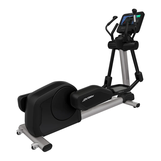
- Page 1 INTEGRITY+ AND CLUB SERIES+ CROSS-TRAINER INX-SE4-XF-13, INX-SL-XF-13, CSX-SL, CSX-SE4 Assembly Instructions 1023156-0001 REV AA...
- Page 3 Latin America and Caribbean* Germany, Austria, and Switzerland Hong Kong Life Fitness, LLC Life Fitness Europe GMBH Life Fitness Asia Pacific LTD 10601 W Belmont Ave Neuhofweg 9 26/F, Global Trade Square Franklin Park, IL 60131 U.S.A. 85716 Unterschleißheim...
- Page 4 User and Service Documents Link https://lifefitness9512.zendesk.com/hc/en-us https://www.lftechsupport.com/web/document-library/documents Additional information is available online using the links above. أ علاه إل ر إبط باستخدإم إ لإ ن تر نت على إضافية معلومات تتوفر 点击上面的链接可在线获取更多信息。 Flere oplysninger er tilgængelige online gennem linket ovenfor. Bijkomende informatie is online beschikbaar via bovenstaande link.
-
Page 5: Table Of Contents
Copyright 2023, Life Fitness, LLC. All Rights Reserved. Life Fitness, Hammer Strength, Cybex, ICG and SCIFIT are registered trademarks of Life Fitness, LLC and its affiliated companies and subsidiaries. Disclaimer: Images and specifications are current as of the date of publication and are subject to change. -
Page 6: Safety Instructions
• Life Fitness Family of Brands does not warrant nor guarantee that component parts used in the manufacture of products offered under the Life Fitness Family of Brands are latex-free. Users of these products must take all necessary precautions to prevent accidental contact that could lead to an adverse latex reaction. - Page 7 • Allow LCD consoles to “normalize” with respect to temperature for one hour before plugging the unit in and using. • When the product is not in use, Life Fitness recommends unplugging the product. Disconnect from the electrical outlet when not in use, and before putting on or taking off parts.
-
Page 8: Consignes De Sécurité
• Life Fitness Family of Brands ne garantit pas que les composants utilisés dans la fabrication des produits proposés dans la Life Fitness Family of Brands sont exempts de latex. Les utilisateurs de ces produits doivent prendre toutes les précautions nécessaires pour éviter un contact accidentel qui pourrait entraîner une réaction indésirable au... - Page 9 à la clientèle. Nous vous en fournirons de nouvelles. Les étiquettes d’avertissement sont expédiées avec les appareils et doivent être installées avant utilisation de ces derniers. Life Fitness Family of Brands n’est pas responsable des étiquettes manquantes ou endommagées.
-
Page 10: Trainer
Where to Place and How to Stabilize the Cross-Trainer Read the entire manual before setting up the cross-trainer. After following all Safety Instructions, move the unit to the location where it will be used. Allow 1 ft. (0.3 m) of clearance in front of the cross-trainer and at least 2 ft. (0.6 m) on the side. -
Page 11: Electrical Power Requirements (Applicable For Units Using External Power Supply)
The Integrity SL console is powered by a rechargeable 6-volt battery. Check the battery by pressing the GO button. The console should beep and light up. The console will display the Life Fitness logo. If a prompt doesn’t appear, mount the unit and begin pedaling. The console should light up and programming a workout should be possible. -
Page 12: Product Overview
2. Product Overview Product Features Item Description Console Contact Heart Rate Sensors Cup Holder Pedal Leg Leveler Transport Wheels Resistance Level Up / Down Controls Connections The following connection receptacle is located at the front of the cross-trainer. Item Description Coaxial Connection Power Input CAT5e Network / Ethernet... -
Page 13: Service And Technical Data
3. Service and Technical Data Preventive Maintenance Tips NOTE: Safety of the equipment can be maintained only if the equipment is examined regularly for damage or wear. Keep the equipment out of use until defective parts are repaired or replaced. Pay special attention to parts that are subject to wear, as outlined below. -
Page 14: Preventive Maintenance Schedule
Preventive Maintenance Schedule Item Weekly Monthly Biannually Console Overlays Clean Inspect Bottle Holders / Accessory Clean Inspect Trays Console Mounting Bolts Inspect Hardware Inspect Frame Clean Inspect Plastic Covers Clean Inspect Lifepulse Sensors Clean / Inspect Leg Levelers Inspect / Adjust Pedals Clean Inspect... -
Page 15: Troubleshoot The Lifepulse™ Sensors
1. Verify the symptom and review the operating instructions. The problem may be unfamiliarity with the product and its features and workouts. 2. Locate and write down the serial number of the unit which is located on the top right of the front stabilizer. 3. Contact Life Fitness Customer Support Services at http://www.lifefitness.com. Page 13 of 25... -
Page 16: Assembly Procedure
4. Assembly Procedure Hardware and Required Tools Item Description Qty. M8 X 20 FLANGE HEX HEAD CAP SCREW M6 X 16 PHILLIPS PAN HEAD SCREW GROMMET M5 X 14 PHILLIPS PAN HEAD SCREW M4.2 X 10 PHILLIPS PAN HEAD SCREW M4.2 X 19 PHILLIPS PAN HEAD SCREW NUT: M8 X 1.25-6H, DIN, UNF, HEX, LOCKNUT (for Moving Handles) NUT: M8 X 1.25-6H, HEX, LOCK, ZINC, CLASS 10... -
Page 17: Before You Begin
Before You Begin 1. The console support weldment is positioned face down in the parts tray table packaging. Item Description Qty. Console Support Weldment Parts Tray Table Packaging CAUTION: Remove any protective covering / tape from the monocolumn and console support weldment prior to attaching to base! Failure to remove the protective covering can cause improper grounding! 2. -
Page 18: Attach Bullhorn
Attach Bullhorn Item Description Qty. Bullhorn M8 X 20 Flange Head Cap Screw 27 Nm (19.91 ft. lbs.) Page 16 of 25... -
Page 19: Attach Moving Handles
Attach Moving Handles Run Heart Rate Cable and Keypad Cable down through the opening and make connections. Item Description Qty. Handlebar, Left Handlebar, Right M8 Locknut 27 Nm (19.91 ft. lbs.) Attach Upper Right and Left Shrouds NOTE: Check for proper clip engagement after installing the upper shrouds. -
Page 20: Insert Cup Holder
Insert Cup Holder NOTE: Align cup ribs with shroud openings. Rotate cup counterclockwise to lock. Description Qty. Cup Holder Page 18 of 25... -
Page 21: Attach Deadshaft Covers
Attach Deadshaft Covers 1. Secure rear deadshaft cover to rocker arm using one screw. Item Description Deadshaft Cover, Rear M6 X 16 Phillips Pan Head Screw 1.5 Nm (13.3 in. lbs.) 2. Add grommets to rear deadshaft cover. Interlock the front deadshaft cover into the rear deadshaft cover. Item Description Deadshaft Cover, Front... -
Page 22: Base To Console Cable Connections
Base to Console Cable Connections Discover SE4 Item Description Ethernet STB HDMI STB IR CSAFE Base Power Base Signal (Lifepulse, Base Switches) Base Comm RF Coax Integrity SL Item Description CSAFE Base Signal (Lifepulse, Base Switches) Base Power Base Comm TV (optional) Page 20 of 25... -
Page 23: Attach Console
Attach Console NOTE: Use the hook on top of the console support weldment to aid in console installation. Discover SE4 (16" or 24") Integrity SL Item Description Qty. Console M5 X 14 Phillips Pan Head Screw 1.9 Nm (1.4 ft. lbs.) Page 21 of 25... -
Page 24: Attach Rear Console Shroud Assembly
Attach Rear Console Shroud Assembly 1. Insert grommets into the two holes on the back of the console support weldment. 2. Push the clips on top of the rear console shroud assembly into the corresponding slots on the console support weldment. -
Page 25: Specifications
5. Specifications Specifications Heavy / Commercial EN ISO 20957 Class SA Models: INX-SL-XF-13, INX-SE4-XF-13 Designed Use Home EN ISO 20957 Class HA Models: CSX-SL, CSX-SE4 Maximum User Weight 400 lbs. / 181 kg Drive Type Generator Pedal Speed Range 2.5 - 14 mph (4 - 22.5 kph) Resistance Levels Power Requirements See Electrical Power Requirements Section... -
Page 26: Getting Started How To Get Parts And Service
Who Pays Transportation and Insurance For Service If the Product or any covered part must be returned to a service facility for repairs, We, Life Fitness Family of Brands, will pay all transportation and insurance charges for the first year. You are responsible for transportation and insurance charge after the first year. -
Page 27: Changes In Warranty Not Authorized
Changes in Warranty Not Authorized No one is authorized to change, modify or extend the terms of this limited warranty. Effects of State Laws This warranty gives you specific legal rights, and you may have other rights which vary from state to state and country by country.
Need help?
Do you have a question about the INTEGRITY+ Series and is the answer not in the manual?
Questions and answers
Display not working, where is the battery