Advertisement
Quick Links
RE..610..
Video module 2-wire
RE..510..
Video insert replacement 2-wire
1
Safety instructions
Electrical equipment may only be installed and
assembled by a qualified electrician in
accordance with the relevant installation
z
standards, guidelines, regulations, directives,
safety and accident prevention regulations of
the country.
When installing and laying cables, always
comply with the applicable regulations and
standards for SELV electrical circuits.
These instructions are an integral component
of the product and must be retained by the end
user.
Design and layout of the device
(1)
(2)
(3)
(4) (5)
Figure 1: Front video module
(1)
(2)
(3)
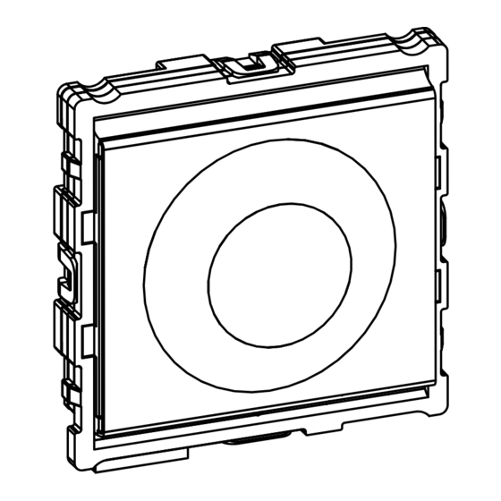
Figure 2: Front video insert
(1) Microphone
(2) Locating screw for camera
(Allen key supplied)
(3) Twilight sensor for call button
(4) Camera
(5) Loudspeaker openings
(6) Module carrier (according to reference)
(7) Centre plate (only with video modules)
(8)
(9)
(10)
(11)
(12)
Figure 3: Back
(8) Adjustment button Upwards
(9) 7-segment display
(10) Selection button
(11) Adjustment button downwards
(12) Connection for module connecting cable
(13) Connection terminal block
Function
The device works in the 2-wire bus system and
enables communication via sound and image.
Correct use
- for surface-mounted, flush-mounted or built-in
installation
- Not compatible with intercom systems of other
manufacturers
- suitable for use exterior applications
Product characteristics
- One-man commissioning
- expandable for modules, e.g. call push-button
- Call push-button acknowledge tone (can be
switched off)
- Call button, light release or door release can be
adjusted even without any function
- Switch-on brightness level of the call button
backlighting adjustable
- Colour camera
- invisible, glare-free IR LED night lighting
- temperature controlled camera heating for clear
view
- scratch-proof camera cover
- Loudspeaker and microphone protected against
sabotage
- Volume and microphone sensitivity settable
- Door release contact on 1 ... 10 s adjustable
- Door release without previous call adjustable in
single door systems
Operation of call push-buttons
Call push-buttons are connected to the device.
(6)
(7)
Establish call (ringing)
z Press the call push-button assigned to the
desired subscriber.
If configured, the call push-button activation is
confirmed by an acknowledge tone. Addressed
indoor stations are called.
Switch-on lights
A call push-button is configured and labelled for
lighting control.
z Press the call push-button for lighting.
If configured, the call push-button activation is
(4)
(5)
confirmed by an acknowledge tone. The light
contact of a line power supply is closed for the
set time.
Label call push-button
z Keep call push-button pressed on one side.
On the opposite side, the lever opening (14) is
accessible for a screwdriver.
z Position the screwdriver in the lever opening
(14) and release the interlock (Figure 4).
z Remove cover with name plate insert.
(13)
Figure 4: Removing name plate cover
(14) Lever opening
z Label name plate insert if required.
z Insert name plate insert, prepared foil or prepa-
red labelling strip into the cover.
z Press on cover.
Do not use any paper for the name plate insert,
P
since moisture and UV light will damage the
paper and labelling.
(14)
6LE002632A Ind. A
Advertisement

Related Manuals for ELCOM RE 610 Series


Summary of Contents for ELCOM RE 610 Series
- Page 1 Safety instructions Correct use - for surface-mounted, flush-mounted or built-in Electrical equipment may only be installed and installation assembled by a qualified electrician in - Not compatible with intercom systems of other accordance with the relevant installation manufacturers standards, guidelines, regulations, directives, - suitable for use exterior applications safety and accident prevention regulations of the country.
- Page 2 UV-resistant foil with laser printing is suitable Connect device for labelling as well as labelling devices for The connection cables and indoor stations are labelling strip: connected to the line power supply while taking - small buttons - 12 mm the maximum cable lengths and attenuations into - medium buttons - 30 mm account (see operating instructions of the line power...
- Page 3 The menu entry flashes alternately with the Error Error cause Counter actions current address/function. code z With select the required address Communication error If the error per- between device and sists, the call or function for light push-button, call push-button mod- push-button door release push-button or for no function.
- Page 4 Appendix Technical data Operating voltage 22 ... 24 V= Current consumption camera (Stand-by) ca. 8 mA Current consumption camera (operation) max. 240 mA Current consumption camera heating (operation) 100 mA (17) Current name plate lighting per call push-button module 45 mA Figure 12: Camera alignment video insert Menu Backlighting On...
Need help?
Do you have a question about the RE 610 Series and is the answer not in the manual?
Questions and answers