
Related Manuals for Classic Exhibits VISIONARY DESIGNS MOD-1703


Summary of Contents for Classic Exhibits VISIONARY DESIGNS MOD-1703
- Page 1 © 2023 Order #XXXXX MOD-1703 Backlit Counter BACK VIEW FRONT VIEW SETUP INSTRUCTIONS If you would like to tell us about your experience with your setup instructions please email us at info@classicexhibits.com...
- Page 2 © 2023 Order #XXXXX General Information General Setup Instructions - Read entire setup instruction manual prior to WARNING unpacking parts and pieces. - The setup instructions are created specifically for this configuration. - Setup instructions are laid out sequentially in steps, including exploded views with detailed explanation for assembly.
- Page 3 © 2023 Order #XXXXX CEI110 Assembly & SEG Installation Upper Horizontal Extrusion CEI110 Corner Connection: Corner Corner Connectors Connectors 1) Loosen knobs, then slide vertical extrusions onto corner connectors of lower horizontal extrusion. Adjust connectors if necessary to prevent gaps in connection. 2) Slide corner connectors of upper horizontal...
- Page 4 © 2023 Order #XXXXX Counter Assembly Item Qty. Description Steps: 39.5”h CEI110 Vertical Extrusion 1) Attach vertical [1] to vertical [2]. See CEI110 to S40 Connection detail. 39.5”h S40 Vertical Extrusion Repeat step, attaching vertical [4] to vertical [3]. 39.5”h S40 Vertical Extrusion 2) Connect horizontals [5,6] between verticals [2,3].
- Page 5 © 2023 Order #XXXXX Counter Assembly (cont’d) Item Qty. Description Steps: 38.752”h TSP2 Vertical Extrusion 1) Assemble horizontals [13,14] between verticals [11,12] inserting infill; 35.853”h GS310 Veritcal Extrusion Attach Brackets to top & bottom of horizontals [13,14] using bolts. 2.955”w Z140 Horizontal Extrusion Refer to Corner Assembly detail.
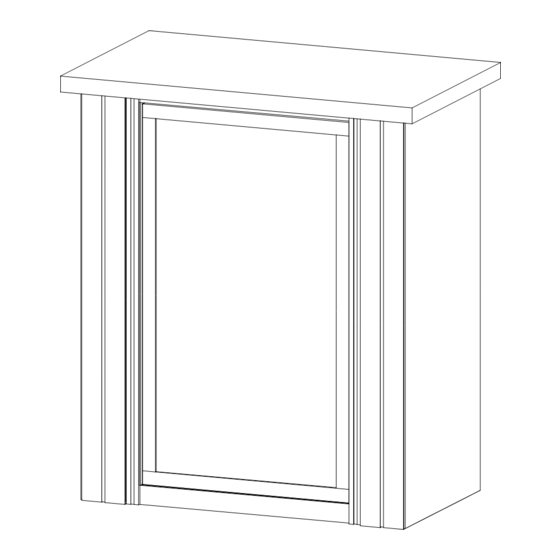
- Page 6 © 2023 Order #XXXXX Counter Assembly (cont’d) Steps: 1) Apply SEG graphics to assembled base. Refer to the SEG Installation general information page. 2) Place Shelf onto pins. See Shelf Pin detail. 3) Attach Counter Top to assembled base. See Counter Top Attachment detail.
Need help?
Do you have a question about the VISIONARY DESIGNS MOD-1703 and is the answer not in the manual?
Questions and answers