Table of Contents
Advertisement
Quick Links
INSTALLATION MANUAL
UL version
TSM_UL_IM_Feb_2016_Rev D
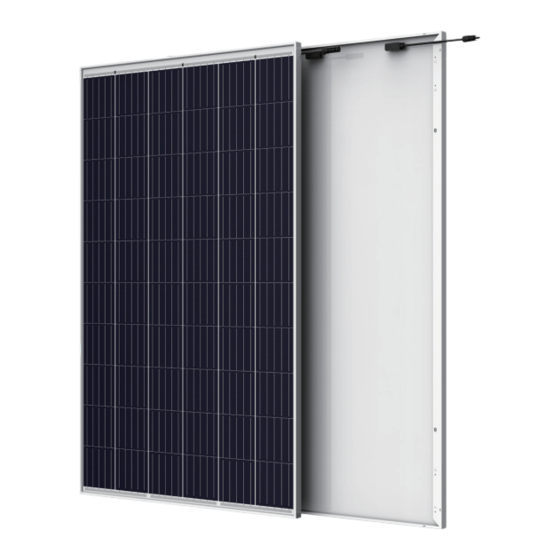
The Allmax Module
The Tallmax Module
The Honey M Plus Module
The Tallmax M Plus Module
The Trinasmart Module
The Trinaswitch Module
The Trinapeak Module
TSM-PD05
TSM-PD05.05
TSM-PD05.08
TSM-PE05A
TSM-PE05A.08
TSM-PD14
TSM-PE14A
TSM-PE14A.08
TSM-DD05A(II)
TSM-DD05A.05(II)
TSM-DD05A.08(II)
TSM-DD14A(II)
TSM-DD14A.05(II)
TSM-DD14A.08(II)
TSM-DD05A.052(II)
TSM-DD05A.082(II)
TSM-PD05.052
TSM-PD05.082
TSM-PD14.002
TSM-DD05A.08S(II)
TSM-DD05A.05S(II)
TSM-PD05.08S
TSM-PD05.08C
TSM-PD05.08D
Advertisement
Table of Contents

Related Manuals for Trina Solar TSM-PD05


Summary of Contents for Trina Solar TSM-PD05
- Page 1 INSTALLATION MANUAL UL version TSM-PD05 TSM-PD05.05 The Allmax Module TSM-PD05.08 TSM-PE05A TSM-PE05A.08 TSM-PD14 The Tallmax Module TSM-PE14A TSM-PE14A.08 TSM-DD05A(II) The Honey M Plus Module TSM-DD05A.05(II) TSM-DD05A.08(II) TSM-DD14A(II) The Tallmax M Plus Module TSM-DD14A.05(II) TSM-DD14A.08(II) TSM-DD05A.052(II) TSM-DD05A.082(II) The Trinasmart Module TSM-PD05.052 TSM-PD05.082...
-
Page 2: Table Of Contents
Table of Content DISCLAIMER OF LIABILITY ....................- 3 - SAFETY PRECAUTIONS ....................... - 3 - UNPACKING AND STORAGE ....................- 5 - 3.1. PRODUCT IDENTIFICATION ....................- 5 - ENVIRONMENTAL CONSIDERATIONS ................- 5 - 4.1. CLIMATE CONDITIONS ....................... - 6 - SITE SELECTION ........................ -
Page 3: Disclaimer Of Liability
Trina Solar assumes no responsibility for any infringement of patents or other rights of third parties that may result from use of the module. No license is granted by implication or under any patent or patent rights. - Page 4 Rated electrical characteristics are within ± 10 percent of measured values at Standard Test Conditions of 1000 W/m², 25°C cell temperature and AM 1.5 solar spectral irradiance. The fire rating of a Trina Solar PV module is valid only when mounted in the manner specified in the mechanical mounting instructions of this installation manual.
-
Page 5: Unpacking And Storage
after 2016-10-25) For cUL listed products only: Fire class rating: C The fire rating of the module is valid only when mounted in the manner specified in the mechanical mounting instructions. The module is considered to be in compliance with UL1703 only when the module is mounted in the manner specified by the mounting instructions. -
Page 6: Climate Conditions
SITE SELECTION Trina Solar Modules can be mounted in landscape or portrait orientation however the impact of dirt shading the solar cells can be minimized by orienting the product in landscape. Solar module is recommended to be installed at an optimized tilt angle to maximize the energy output. It is roughly equal to the latitude of the project site as a rule of thumb, facing to equator. -
Page 7: Mounting With Bolts
1) Aluminum Frame 2) M8 Stainless Bolt Flat Stainless Washer Spring Stainless Washer 5) HEX Stainless Nut B. Mounting with Clamps Trina Solar has tested its modules with a number of clamps from different manufacturers and recommends the - 7 -... - Page 8 use of clamps which have an EPDM or similar insulating washer, fixing bolt of at least M6. The clamp must overlap the module frame by at least 0.28in but no more than 0.39in. Use at minimum 4 clamps to fix modules on the mounting rails. ...
-
Page 9: Mounting With Single-Axis Tracking System
Other mounting configurations can be used. However, failure to comply with the above recommendations will result in a lowering of the load handling (snow/wind load) capabilities below the product specification 5400/3800Pa and product failure as a result of an overload situation will not be covered by the Trina Solar warranty. C. Mounting with Single-axis Tracking System... -
Page 10: Grounding
Codes. The grounding conductor must then make a connection to earth using a suitable earth ground electrode. Trina Solar modules can be installed with the use of third party listed grounding devices for grounding the metallic frames of PV modules. The devices have to be installed in accordance with the grounding device manufacturer’s specified instructions. - Page 11 Figure 5. Tyco grounding bolt # 1954381-2 (Not applicable for TRINAMOUNT module series) 1) Wire slot (available for 0.006 to 0.025in cable) 2) Slider 3) Bolt 4) Base 5) Nut Tyco grounding hardware comes in a package that includes the grounding bolt, mounting and grounding hex nut.
-
Page 12: Module Wiring
Trina Solar modules are provided with stranded copper cables with a cross sectional area of 0.006in² which are rated for 1500 V DC, 90°C and are UV resistant. All other cables used to connect the DC system should have a similar (or better) specification. -
Page 13: Fusing
7.2. INVERTER SELETION AND COMPATIBILITY When installed in systems governed by IEC regulations, Trina Solar modules normally do not need to be electronically connected to earth and therefore can be operated together with either galvanically isolated (with transformer) and transformerless inverters. - Page 14 Cover the front surface of modules by an opaque material when repairing. Modules when exposed to sunlight generate high voltage and are dangerous. Trina Solar PV modules are equipped with bypass diodes in the junction box. This minimizes module heating and current losses.
Need help?
Do you have a question about the TSM-PD05 and is the answer not in the manual?
Questions and answers