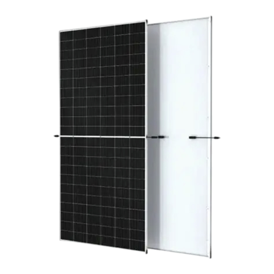
Trina Solar Vertex TSM-DE19R 575 User Manual

Back sheet-glass framed module

Advertisement

Quick Links

Vertex User Manual _ Back Sheet-Glass Framed Module

1.
1.1
1.2
2.
2.1
2.2
2.3
3.
3.1
3.2
3.3
3.4
4.
4.1
4.2
5.
................................................................................................................................ 9
6.
7.
7.1
7.2
8.
9.
9.1
9.2
9.3
Date: Nov 26th, 2020
......................................................................................... 2
................................................................................................................. 2
............................................................................................ 2
............................................................................................................ 2
..................................................................................................................... 2
....................................................................................................... 2
...................................................................................................... 2
............................................................................................. 4
..................................................................................................................... 6
.................................................................................................... 6
................................................................................................... 6
....................................................................................................... 7
........................................................................................................................ 8
........................................................................................................................... 9
............................................................................................... 9
............................................................................................. 9
.............................................................................................................. 15
................................................................................................................ 21
............................................................................................. 22
Doc No: PS-M-0906
.................................................................. 1
.................................................................................. 3
............................................................................ 3
........................................................... 5
............................................................. 9
..................................................................................... 19
........................................................................ 20
..................................................................... 20
.................................................................... 21
.................................................................. 22
............................................................... 22
......................................................................... 22
Ver: B
.................................................. 20
Page 1 of 22

Advertisement

Table of Contents
loading
Need help?

Need help?

Do you have a question about the Vertex TSM-DE19R 575 and is the answer not in the manual?

Questions and answers

Subscribe to Our Youtube Channel

Summary of Contents for Trina Solar Vertex TSM-DE19R 575

  • Page 1: Table Of Contents

    Vertex User Manual _ Back Sheet-Glass Framed Module ..............1 Vertex User Manual _ Back Sheet-Glass Framed Module ..................2 INTRODUCTION FOR USER MANUAL ......................... 2 DISCLAIMER .................... 2 LIMITATION OF LIABILITY ......................2 SAFETY PRECAUTIONS ........................2 WARNING ....................... 2 GENERAL SAFETY ......................
  • Page 2: Introduction For User Manual

    Please keep this Manual for future reference. 1.1 DISCLAIMER Trina Solar reserves the rights to change this User Manual without prior notice. Failure of the customer to follow the requirements outlined in this Manual during the installation of the module will result in the invalidity of product's limited warranty.
  • Page 3: Unload/Transprotation/Storage

    Do NOT scratch the output cable or bend it with force. The insulation of output cable can break and may result in electricity leakage or shock. Do NOT use water to extinguish fires of an electrical origin. Do NOT install or handle modules when they are wet or during periods of high wind. At the installation site, take care to keep modules and in particular their electrical contacts, clean and dry before installation.
  • Page 4: Unloading Warnning

    3.1.5 Do NOT step on the package and module 3.1.6 The carton can be recycled 3.1.7 Modules shall be stacked as required, not 3.1.8 One module shall be handled by at least exceeding the maximum number of layers printed two persons together on the outer packaging.
  • Page 5: Secondary Transport And Warnning

    3.2.3 Store the module in a dry and ventilated 3.2.4 Do Not stack the modules at the project place site. 3.2.5 Cover the module with waterproof material to prevent it from moisture SECONDARY TRANSPORT AND WARNNING 3.3.1 Do NOT remove the original packaging if 3.3.2 finished package...
  • Page 6: Storage

    3.3.5 Only one layer stacking is only allowed for 3.3.6 No transport or handling by pedi-cab as transport at the project site shown below; 3.3.7 Do Not transport the module with rope as 3.3.8 Do Not carry the modules on the back of shown below: one person as shown below: STORAGE...
  • Page 7: Unpacking Step

    The work surface is required to be level to ensure that the package can be placed stably, avoiding sliding. Wear protective gloves during unpacking to avoid hand injury and fingerprints on the glass surface. Module information and unpacking instructions can be found on the outside of each package. Please read the instructions before unpacking.
  • Page 8: Site Selection

    Position the modules to minimize the chances of shading at any time of the day. Trina Solar recommends that the module should be installed at a working ambient temperature of - 20℃~50℃. The module's limit working ambient temperature range is from -40℃ to 85℃. Maximum altitude less than or equal to 2000m .The maximum mechanical load is 5400 on the front and 2400...
  • Page 9: Tilt Angle

    6. TILT ANGLE The tilt angle measurement of the PV module refers to measuring the angle between the module and the horizontal ground surface. For different projects there are different mounting angles. Trina Solar recommends that the mounting tilt angle should be NOT less than 10° , or in accordance with local regulations or follow the recommendations of experienced PV module installers.
  • Page 10 Installation holes of 4- φ9*14 mm are used for routine installation, as shown in Figure 1. To maximize mounting longevity, Trina Solar strongly recommends the use of corrosion proof (stainless steel) attachment hardware.
  • Page 11 Mechanical load. The actual load is + 6000Pa/-4000Pa B. Mounting with Clamps  Trina Solar has tested its modules with a number of clamps from different manufacturers, fixing bolt of at least M8. The length of clamp ≥40mm(1.57in) length clamp ≥60mm...
  • Page 12 and snow loads, additional clamps may be required to ensure that modules can bear the load. Applied torque should refer to mechanical design standard according to the bolt customer is using, ex: M8 ---- 16-20N.m(140-180lbf.in) End Clamp installation Middle Clamp installation Mechanica Safety Module...
  • Page 13 Vertex_ Back sheet- +3600 Pa /- Glass 1600 Pa Framed Module_ DE19 NOTE 1. This installation may cause the cell covered, so Trina does not recommend this installation for Bifacial Dual Glass Module. 2.The above clamp range distance is from the middle point of module to the clamp.
  • Page 14 φ7*10 mm are used for Single-axis tracking system installation, as shown in Figure 2 To maximize mounting longevity, Trina Solar strongly recommends the use of corrosion proof (stainless steel) attachment hardware. Secure the module in each fixing location with an M6 bolt and two flat washer, a spring washer and nut.
  • Page 15 1) M6 hex bolt 2) flat stainless washer 3) spring stainless washer 4) hex stainless nut Mechanical Load Module Safety factor Mounting Direction Pressure Vertex_ Back sheet-Glass Framed +1600 Pa /-1600 Pa Module_DE18M(II) *NOTE: The above-described distance is from the middle of the bolts to the middle of the bolts.
  • Page 16: Grounding

     Trina Solar modules can be installed with the use of third party listed grounding devices for grounding the metallic frames of PV modules. The devices have to be installed in accordance with the grounding device manufacturer’s specified instructions.
  • Page 17  Grounding hardware comes in a package that includes the grounding screw, flat washer、star washer and wire  Electrical contact is made by penetrating the anodized coating of the aluminum frame, and tightening the mounting screw (come with the star washer) to the proper torque of 25lbf.in. ...
  • Page 18 Figure 5. Tyco grounding bolt # 1954381-2 (NOT applicable for TRINAMOUNT module series) 1) Wire slot (available for 0.006 to 0.025in cable) 2) Slider 3) Bolt 4) Base 5) Nut Tyco grounding hardware comes in a package that includes the grounding bolt, mounting and grounding hex nut.
  • Page 19: Electrical Installation

    Trina Solar modules are provided with stranded copper cables with a cross sectional area of 4mm² (0.006in² ) which are UV resistant. All other cables used to connect the DC system should have a similar (or better) specification.
  • Page 20: Inverter Selection And Compatibility

    Trina Solar requires that every VERTEX series PV module string should be fused prior to be connected with other strings. If a different method is desired, please contact Trina Solar customer service or technical support team for consultation.
  • Page 21: Connector And Cable Inspection

    module heating and current losses. o Do NOT open the junction box to change the diodes even if they malfunction. o In a system using a battery, blocking diodes are typically placed between the battery and the PV module output to prevent battery discharge at night. In the event that a module is damaged (broken glass or a scratch on back sheet) and needs to be replaced o Observe the safety precautions listed earlier in this Manual...
  • Page 22: Requirements For Water Quality

    10. REPORTING TECHNICAL ISSUES or CLAIMS  Contact your installer  Contact Trina Solar after sales service team at http://customerservice.trinasolar.com/  Submit the Customer Feedback form at: http://www.trinasolar.com/ and one of our technical service representatives will contact you within 5 business days.

This manual is also suitable for:

Vertex tsm-de19r 570Vertex tsm-de21 665

Table of Contents