
Related Manuals for Nidec Power Module Frame 12


Summary of Contents for Nidec Power Module Frame 12
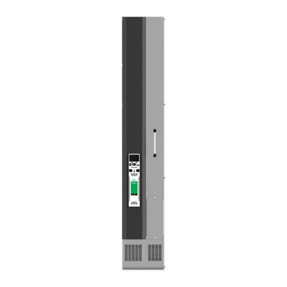
- Page 1 Power Installation Guide Power Module Frame 12 Universal Variable Speed AC Drive for induction and servo motors Part Number: 0478-0613-01 Issue: 2...
- Page 2 All rights reserved. No parts of this guide may be reproduced or transmitted in any form or by any means, electrical or mechanical including photocopying, recording or by an information storage or retrieval system, without permission in writing from the publisher. Copyright © January 2020 Nidec Control Techniques Ltd...
-
Page 3: Safety Information
How to use this guide This user guide provides complete information for installing the drive. The information is in logical order, taking the reader from receiving the drive through to installation. NOTE There are specific safety warnings throughout this guide, located in the relevant sections. In addition, Chapter 1 Safety information contains general safety information. -
Page 4: Table Of Contents
Contents Technical data ........63 Safety information ......... 6 Drive technical data ..........63 Warnings, Cautions and Notes ......6 Optional external EMC filters ....... 67 General information ..........6 Responsibility ............6 Compliance with regulations ........6 Electrical hazards ..........6 Stored electrical charge ......... - Page 5 EU Declaration of Conformity 1. Product model Unidrive-M Variable Speed Motor Drives. 2. Name and address of the manufacturer Nidec Control Techniques Ltd The Gro Newtown Powys SY16 3BE Registered in England and Wales. Company Reg. No. 01236886 Telephone: 00 44 1686 612300 E-mail: marketing.control techniques@mail.nidec.com...
-
Page 6: Warnings, Cautions And Notes
Safety information Product information Mechanical installation Electrical Installation Technical data Safety information Electrical hazards The voltages used in the drive can cause severe electrical shock and/or Warnings, Cautions and Notes burns and could be lethal. Extreme care is necessary at all times when working with or adjacent to the drive. -
Page 7: Motor
Safety information Product information Mechanical installation Electrical Installation Technical data 1.11 Motor The safety of the motor under variable speed conditions must be ensured. To avoid the risk of physical injury, do not exceed the maximum specified speed of the motor. Low speeds may cause the motor to overheat because the cooling fan becomes less effective, causing a fire hazard. -
Page 8: Product Information
Safety information Product information Mechanical installation Electrical Installation Technical data Product information This guide provides the information necessary to install and commission the Unidrive M Frame 12 cubicle drive. The power module is intended to be installed into the cubicle by the system integrator using the standard engineering accessories (SEA’s). The SEA’s consist of: •... -
Page 9: Nameplate Description
Safety information Product information Mechanical installation Electrical Installation Technical data Nameplate description Figure 2-2 Drive rating labels NOTE Date code format The date code is four numbers. The first two numbers indicate the year and the remaining numbers indicate the week of the year in which the drive was built. -
Page 10: Ratings
Safety information Product information Mechanical installation Electrical Installation Technical data Ratings The continuous current ratings given are for maximum 40 °C (104 °F),1000 m altitude and 2 kHz switching frequency. Derating is required for higher switching frequencies, higher ambient temperatures and high altitude. For further information, refer to section 5 Technical data, Power and current ratings (Derating for switching frequency and temperature). -
Page 11: Product Features
Safety information Product information Mechanical installation Electrical Installation Technical data Product features The power module is to be installed into a cubicle. It can be transported using the lifting trolley or can be wheeled using the castors. Figure 2-3 Features of the power module (with control pod fitted) Lifting points Input power busbars... - Page 12 Safety information Product information Mechanical installation Electrical Installation Technical data NOTE The power module is supplied without a control pod. The drive derivative, e.g. M700, is achieved by fitting the appropriate control pod. Figure 2-4 Features of the drive cubicle (with control pod fitted) Unidrive M Frame 12 Power Installation Guide Issue Number: 1...
- Page 13 Safety information Product information Mechanical installation Electrical Installation Technical data Power module accessories The following items in Table 2-3 will be provided with the power module. The part number of the kit box is 3470-0082. Table 2-3 Parts supplied with the power module Part number Description Part supplied...
- Page 14 Safety information Product information Mechanical installation Electrical Installation Technical data 2.6.3 Pallet truck lifting kit To aid the installation of the power module into the cubicle there are two types of accessory. 1. Pallet truck lifting kit – This includes a ramp and a transport cradle for transporting the power module using a pallet truck. Part number 6500-0159. Figure 2-5 Pallet truck lifting kit 2.
-
Page 15: Mechanical Installation
Safety information Product information Mechanical installation Electrical Installation Technical data Mechanical installation This chapter describes how to use all mechanical details to install the power module. Key features of this chapter include cubicle installation, terminal location and torque settings. Safety information Isolation device Follow the instructions The AC supply must be disconnected from the drive using an... -
Page 16: Lifting The Power Module
Safety information Product information Mechanical installation Electrical Installation Technical data 3.3.5 Fire protection Lifting the Power Module The drive enclosure is not classified as a fire enclosure. A separate fire enclosure must be provided. For installation in the USA, a NEMA 12 enclosure is suitable. Lifting and handling Always lift the drive by the lifting points. -
Page 17: Rittal Vx25 Cubicle Fitting Kit
Safety information Product information Mechanical installation Electrical Installation Technical data 3.3.7 Hazardous areas The drive must not be located in a classified hazardous area. Hot surfaces Component IP ratings Care must be taken when opening the cubicle door as some The Power Module is rated to IP00. -
Page 18: Input And Output Wiring Kits
Safety information Product information Mechanical installation Electrical Installation Technical data Input and output wiring kits The input and output wiring kits and earthing plate kit are supplied as separate parts. Figure 3-5 Input, output wiring kit and earthing plate kits Unidrive M Frame 12 Power Installation Guide Issue Number: 1... -
Page 19: Tools Required For Installation
Safety information Product information Mechanical installation Electrical Installation Technical data Tools required for installation The tools required for installing the power module into the cubicle are shown in Figure 3-4. Figure 3-6 Tools required for installation Torque wrench (RS part number 264-2195) Socket size Socket extension bar (RS part number 772-4003) Length... - Page 20 Safety information Product information Mechanical installation Electrical Installation Technical data Cubicle roof plate (VX25) 3.7.1 Stand-alone applications To allow the air to flow through the cubicle the VX25 roof plate (9681.846) must be fitted to the top of the cubicle. For stand-alone applications where attaching the cubicle to a fixed surface is not required the roof plate can be fitted as supplied.
- Page 21 Safety information Product information Mechanical installation Electrical Installation Technical data 3.7.3 Fitting wall brackets to fixed surface With the cubicle in the desired position mark the holes, drill the holes and fasten the wall brackets to the fixed surface as shown in Figure 3-9 Figure 3-9 Fitting the wall brackets 3.7.4...
-
Page 22: Installation Of Power Module Into Cubicle
Safety information Product information Mechanical installation Electrical Installation Technical data Installation of power module into cubicle The following steps should be followed when installing a power module into a cubicle. The required parts are available as part of the power module installation kit. - Page 23 Safety information Product information Mechanical installation Electrical Installation Technical data 3.7.2 Install input and output wiring terminal kits to the cubicle as defined in the specified dimensions below. Figure 3-8 Installation of input and output wiring kits Unidrive M Frame 12 Power Installation Guide Issue Number: 1...
- Page 24 Safety information Product information Mechanical installation Electrical Installation Technical data 3.7.3 Install earthing plates between the wiring kits. Fasten using 8 off M6 nuts and tighten to 6 Nm. Figure 3-9 Installation of earthing plates Unidrive M Frame 12 Power Installation Guide Issue Number: 1...
- Page 25 Safety information Product information Mechanical installation Electrical Installation Technical data 3.7.4 Connect input, output and earth cables to wiring terminal kits. To aid cable installation, the input phase busbars are supplied loose on the input wiring kit. NOTE • Position L3B busbar to the position furthest back on the wiring plate •...
- Page 26 Safety information Product information Mechanical installation Electrical Installation Technical data 3.7.5 Install drive support metalwork into the bottom of the cubicle. Fit 15 off 2486.500 screws at 6 Nm, 3 off M8 x 16 screws at 12 Nm, 4 off M6 x 20 screws at 6 Nm and 1 off M5 x 12 screw at 4 Nm. Figure 3-11 Installation of drive support metal work into bottom of cubicle Unidrive M Frame 12 Power Installation Guide Issue Number: 1...
- Page 27 Safety information Product information Mechanical installation Electrical Installation Technical data 3.7.6 Fit rear lower mounting bracket to cubicle. Fit 3 off M8 x 16 screws in lower rear mounting bracket and tighten to 12 Nm. NOTE The M6 x 16 screws are fitted at section 3.7.16. Figure 3-12 Installation of lower mounting bracket Unidrive M Frame 12 Power Installation Guide Issue Number: 1...
- Page 28 Safety information Product information Mechanical installation Electrical Installation Technical data 3.7.7 If the power module requires transporting to the cubicle, fit the power module into the cradle. If the power module does not require transportation the ramp can be connected directly to the cubicle. See section 3.7.11 for details.
- Page 29 Safety information Product information Mechanical installation Electrical Installation Technical data 3.7.8 Wheel the power module into the cubicle, ensuring alignment of all busbar threaded connections during the final part of movement. Figure 3-14 Transporting the power module on the pallet truck lifting kit NOTE The pallet truck forks are intended to fit underneath the fork supports as shown in part 4 of Figure 3-14.
- Page 30 Safety information Product information Mechanical installation Electrical Installation Technical data 3.7.9 Attach the bridge between the cradle and the cubicle. Figure 3-15 Bridge attachment and removal of stop Unidrive M Frame 12 Power Installation Guide Issue Number: 1...
- Page 31 Safety information Product information Mechanical installation Electrical Installation Technical data 3.7.10 Fit the power module into the cubicle. Ensure terminal busbar alignment is correct. Figure 3-16 Installing the power module into the cubicle Keep fingers clear of front of cubicle when sliding power module. Ensure correct alignment of busbars when locating power module to prevent damage to threads.
- Page 32 Safety information Product information Mechanical installation Electrical Installation Technical data 3.7.11 Installing the cubicle using the ramp only. Ensure terminal busbar alignment is correct. Figure 3-17 Using the ramp to install the power module Push power module slowly up the ramp. Ensure that it is held firmly at all times. The use of gloves is recommended. Wear safety shoes when transporting the power module.
- Page 33 Safety information Product information Mechanical installation Electrical Installation Technical data 3.7.12 Fit 15 x M10 nuts to the main input and output power terminals and ground connections. See section 3.11.5 for location of ground connections. Tighten loosely to ensure that alignment of terminals is achieved. Figure 3-18 Fitting the nuts to the power terminals Care must be taken to prevent the fasteners from falling into the cubicle.
- Page 34 Safety information Product information Mechanical installation Electrical Installation Technical data 3.7.13 Install upper rear mounting bracket using 3 off M8 x 16 and tighten to 12 Nm. Fit 3 off M5 x 12 screws and tighten to 4 Nm Figure 3-19 Rear mounting bracket fitting Care must be taken to prevent the fasteners from falling into the cubicle.
- Page 35 Safety information Product information Mechanical installation Electrical Installation Technical data 3.7.14 Install recirculation baffles to upper right and upper left sides. Insert 3 off M4 x 8 screws into left baffle and tighten to 2 Nm. Insert 3 of Rittal multi-tooth 2486.500 screws in right baffle and tighten to 6 Nm. Figure 3-20 Installation of recirculation baffles Care must be taken to prevent the fasteners from falling into the cubicle.
- Page 36 Safety information Product information Mechanical installation Electrical Installation Technical data 3.7.15 Install upper front mounting bracket and fit 5 off M8 x 16 screws and tighten to 12 Nm. Fit 2 off M5 x 12 screws and tighten to 4 Nm. Fit 2 off 2486.500 screws and tighten to 6 Nm. Figure 3-21 Installation of front mounting bracket Care must be taken to prevent the fasteners from falling into the cubicle.
- Page 37 Safety information Product information Mechanical installation Electrical Installation Technical data 3.7.16 Fit and tighten 2 off M6 x 16 screws in lower rear mounting bracket (section 3.7.6) and tighten to 6 Nm. 3.7.17 Install lower front mounting bracket, fit 3 off M8 x 16 screws and tighten to 12 Nm. Fit 4 off M6 x 20 screws and tighten to 6 Nm.
- Page 38 Safety information Product information Mechanical installation Electrical Installation Technical data 3.7.21 Attach control pod terminal cover and gland plate. Tighten M4 x 12 screw to 2 Nm. Figure 3-23 Attaching control pod terminal cover and gland plate Unidrive M Frame 12 Power Installation Guide Issue Number: 1...
- Page 39 Safety information Product information Mechanical installation Electrical Installation Technical data 3.7.22 Attach terminal covers and fit 2 off M5 x 12 screws. Tighten to 4 Nm. Insert the control pod panel and fit one M4 x 8 screw. Tighten to 2 Nm. Figure 3-24 Attach terminal covers Unidrive M Frame 12 Power Installation Guide Issue Number: 1...
- Page 40 Safety information Product information Mechanical installation Electrical Installation Technical data 3.7.23 Attach left side terminal guard. Fit 5 off M8 x 16 screws through the mounting bracket into 5 off captive nuts (4165.500). Tighten to 12 Nm. Fit 2 off M5 x 12 screws and tighten to 4 Nm. Fit 4 off 2486.500 screws into left hand side terminal guard and tighten to 6 Nm. Figure 3-25 Attach left side terminal guard Care must be taken to prevent the fasteners from falling into the cubicle.
-
Page 41: Terminal Cover Removal
Safety information Product information Mechanical installation Electrical Installation Technical data Terminal cover removal Isolation of the cubicle The AC supply must be disconnected from the drive using the supply isolator before any cover is removed from the drive or before any servicing work is performed. -
Page 42: Dimensions
Safety information Product information Mechanical installation Electrical Installation Technical data Dimensions Figure 3-27 Power Module dimensions (shown in mm) Unidrive M Frame 12 Power Installation Guide Issue Number: 1... -
Page 43: External Emc Filter
Safety information Product information Mechanical installation Electrical Installation Technical data 3.10 External EMC filter To provide customers with a degree of flexibility, external EMC filters have been sourced from two manufacturers: Schaffner and Block. Filter details for each drive rating are provided in the tables below. NOTE If an external EMC filter is to be installed, it must be installed in an incomer cabinet. - Page 44 Safety information Product information Mechanical installation Electrical Installation Technical data Figure 3-29 Block external EMC filter Table 3-5 Block external EMC filter dimensions Part number HLD 103-500/1000 Ø 14 Unidrive M Frame 12 Power Installation Guide Issue Number: 1...
-
Page 45: Electrical Terminals
Safety information Product information Mechanical installation Electrical Installation Technical data 3.11 Electrical terminals 3.11.1 Power module terminals Figure 3-30 Power module terminal position Unidrive M Frame 12 Power Installation Guide Issue Number: 1... - Page 46 Safety information Product information Mechanical installation Electrical Installation Technical data 3.11.2 Location of the power and control terminals Figure 3-31 Location of power and control terminals terminals terminals terminals terminals 3.11.3 Input wiring kit terminal identification for 6 and 12 pulse configurations Figure 3-32 Terminal identification for input wiring kit.
- Page 47 Safety information Product information Mechanical installation Electrical Installation Technical data 3.11.4 Output wiring kit terminal identification Figure 3-33 Terminal identification for output wiring kit Unidrive M Frame 12 Power Installation Guide Issue Number: 1...
- Page 48 Safety information Product information Mechanical installation Electrical Installation Technical data 3.11.5 Location of ground terminals Figure 3-34 Location of ground terminals (NEW FIGURE) Ground connections The equipment must be grounded (earthed). The wiring must conform to local regulations and codes of practice. This is the responsibility of the installer.
-
Page 49: Terminal Sizes And Torque Settings
Safety information Product information Mechanical installation Electrical Installation Technical data 3.12 Terminal sizes and torque settings To avoid a fire hazard, adhere to the specified tightening torques for the power and ground terminals. Refer to the following tables. Table 3-6 Drive control and relay terminal data Terminal Connection size... -
Page 50: Electrical Installation
Safety information Product information Mechanical installation Electrical Installation Technical data Electrical Installation Electric shock risk Permanent magnet motors The voltages present in the following locations can cause Permanent magnet motors generate electrical power if they severe electric shock and may be lethal: are rotated, even when the supply to the drive is disconnected. -
Page 51: Power Connections
Safety information Product information Mechanical installation Electrical Installation Technical data Power connections 4.1.1 AC and DC and brake connections Figure 4-1 Unidrive M frame 12 power connections Output short circuit protection The drive modules are provided with fast-acting electronic short-circuit protection which limits the fault current to typically no more than five times the rated output current and interrupts the current in approximately 20 μs. -
Page 52: Use Of A Residual Current Device (Rcd)
Safety information Product information Mechanical installation Electrical Installation Technical data Use of a residual current device (RCD) There are three common types of ELCB / RCD: • AC - detects AC fault currents • A - detects AC and pulsating DC fault currents (provided the DC current reaches zero at least once every half cycle) •... -
Page 53: Supply Requirements
Safety information Product information Mechanical installation Electrical Installation Technical data Supply requirements Operation with IT (ungrounded) supplies: 4.5.1 AC to AC operation (AC supply to AC motor) Special attention is required when using internal or external EMC filters with ungrounded supplies, because in the event Table 4-2 AC Supply voltage ranges of a ground (earth) fault in the motor circuit the drive may not... - Page 54 Safety information Product information Mechanical installation Electrical Installation Technical data 4.5.6 24 Vdc supply The 24 Vdc supply connected to control terminals provides the following functions: It can be used to supplement the drive’s own internal 24 V supply when multiple option modules are being used and the current drawn by these modules is greater than the drive can supply.
- Page 55 Safety information Product information Mechanical installation Electrical Installation Technical data Table 4-7 Working range of the control 24 Vdc power supply 0V common +24 Vdc Nominal operating voltage 24.0 Vdc Minimum continuous operating voltage 19.2 V Maximum continuous operating voltage 28.0 V Minimum startup voltage 21.6 V...
-
Page 56: Low Voltage Operation
Safety information Product information Mechanical installation Electrical Installation Technical data Figure 4-2 Location of the 24 Vdc power supply connection Low voltage operation With the addition of a 24 Vdc power supply to supply the control circuits, the drive is able to operate from a low voltage DC supply with a range from 24 Vdc to the maximum DC volts. -
Page 57: Ratings
Safety information Product information Mechanical installation Electrical Installation Technical data Ratings The input current is affected by the supply voltage and impedance. Typical input current The values of typical input current are given to aid calculations for power flow and power loss. The values of typical input current are stated for a balanced supply. -
Page 58: Output Circuit And Motor Protection
Safety information Product information Mechanical installation Electrical Installation Technical data Output circuit and motor protection The output circuit has fast-acting electronic short-circuit protection which limits the fault current to typically no more than five times the rated output current and interrupts the current in approximately 20 µs. No additional short-circuit protection devices are required. The drive provides overload protection for the motor and its cable. - Page 59 Safety information Product information Mechanical installation Electrical Installation Technical data Users of 575 V NEMA rated motors should note that the specification for Figure 4-5 Alternative connection for multiple motors (NEW FIGURE) inverter-rated motors given in NEMA MG1 section 31 is sufficient for motoring operation but not where the motor spends significant periods braking.
-
Page 60: Braking
Safety information Product information Mechanical installation Electrical Installation Technical data Braking The instantaneous power rating refers to the short-term maximum power dissipated during the on intervals of the pulse width modulated braking Braking occurs when the drive is decelerating the motor or is preventing control cycle. - Page 61 Safety information Product information Mechanical installation Electrical Installation Technical data amount of energy to be extracted from the load. Unidrive M Frame 12 Power Installation Guide Issue Number: 1...
-
Page 62: Ground Leakage
Safety information Product information Mechanical installation Electrical Installation Technical data 4.10 Ground leakage 4.9.2 Braking resistor software overload The ground leakage current is dependent on whether the internal EMC protection filter is fitted or not. The drive is supplied with the filter installed. The Unidrive M software contains an overload protection function for a Instructions for removing the internal filter are given in section 4.11.4 braking resistor. -
Page 63: Emc (Electromagnetic Compatibility)
Safety information Product information Mechanical installation Electrical Installation Technical data 4.11 EMC (Electromagnetic compatibility) 4.11.1 Immunity This is a summary of the EMC performance of the drive. For full details, refer to the EMC Data Sheet which can be obtained from the supplier of the drive. - Page 64 Safety information Product information Mechanical installation Electrical Installation Technical data Cable layout The input and output cables should be kept separate. A separation of at least 100 mm is recommended. Sensitive signal circuits should be routed away from the drive module. A minimum separation of 300 mm (12 in) is recommended. Any signal cables which are carried inside the motor cable (motor thermistor, motor brake) will pick up large pulse currents via the cable capacitance.
- Page 65 Safety information Product information Mechanical installation Electrical Installation Technical data 4.11.4 Disconnection of the internal EMC filter and line to earth varistors The power module is fitted with an internal EMC filter and three line to earth varistors. These can be disconnected by removing the applicable screw as shown in Figure 4-7.
- Page 66 Safety information Product information Mechanical installation Electrical Installation Technical data • 4.11.5 General requirements for EMC The shields must be directly clamped to the encoder body (no pigtail) and to the drive grounding bracket. This may be achieved Ground (earth) connections by clamping of the individual shields or by providing an additional If ground connections are made using a separate cable, they should run overall shield which is clamped.
- Page 67 Safety information Product information Mechanical installation Electrical Installation Technical data Figure 4-9 Feedback cable connections Ensure good EMC grounding. Connect the shield of the motor cable to the ground terminal of the motor Connection frame using a link that is as short as possible and not exceeding 50 mm at drive (2 in) long.
- Page 68 Safety information Product information Mechanical installation Electrical Installation Technical data As a general rule, if the circuits are to pass outside the building where These products are not intended for use in domestic premises or the drive is located, or if cable runs within a building exceed 30 m establishments directly connected without an intermediate transformer to (98.5 ft), some additional precautions are advisable.
- Page 69 Safety information Product information Mechanical installation Electrical Installation Technical data Technical data Drive technical data 5.1.1 Power and current ratings (Derating for switching frequency and temperature) Table 5-1 Maximum permissible continuous output current @ 40 ºC (104 ºF) ambient temperature Normal Duty Heavy Duty Maximum Permissible continuous output...
- Page 70 Safety information Product information Mechanical installation Electrical Installation Technical data 5.1.5 Storage -40 °C (-40 °F) to +40 °C (104 °F) for long term storage, or to +70 °C (158 °F) for short term storage. Electrolytic capacitors in any electronic product have a storage period after which they require reforming or replacing.
- Page 71 Safety information Product information Mechanical installation Electrical Installation Technical data 5.1.7 IP / UL Rating Shock Bump Test Testing all specimens together in each of three mutually perpendicular The power module is rated to IP00. Once installed in the cubicle the IP axes in turn.
- Page 72 Safety information Product information Mechanical installation Electrical Installation Technical data 5.1.17 Input current, fuse and cable size ratings 5.1.14 Acoustic noise The cooling fans generate the majority of the acoustic noise produced by The input current is affected by the supply voltage and impedance. the drive.
- Page 73 Safety information Product information Mechanical installation Electrical Installation Technical data 5.1.18 Fuses and cable size Fuses The AC supply to the drive must be installed with suitable protection against overload and short-circuits. Table 5-9 shows recommended fuse ratings. Failure to observe this requirement will cause risk of fire. Table 5-9 400 V Drive input current, fuse and cable size rating Maximum...
- Page 74 Safety information Product information Mechanical installation Electrical Installation Technical data Optional external EMC filters Table 5-11 EMC filter details (all models) Schaffner Block Drive Part number Weight Part number Weight 12404800T 12405660T FN 3311-1000-99-C16-R55 5.5 kg (12.1 lb) HLD 103-500/1000 22.5 kg (49.6 lb) 12406600T 12407200T...
- Page 76 Index Altitude ..................63 Cautions ..................6 Cooling method ............... 63 Electrical Installation ..............46 Humidity .................. 63 IP Rating (Ingress protection) ..........64 Mechanical Installation ............14 Notes ..................6 Power ratings ................63 Product information ..............10 Ratings ..................10 Safety Information ...............
- Page 78 0478-0613-01...
Need help?
Do you have a question about the Power Module Frame 12 and is the answer not in the manual?
Questions and answers