
Related Manuals for Nidec LEROY-SOMER


Summary of Contents for Nidec LEROY-SOMER
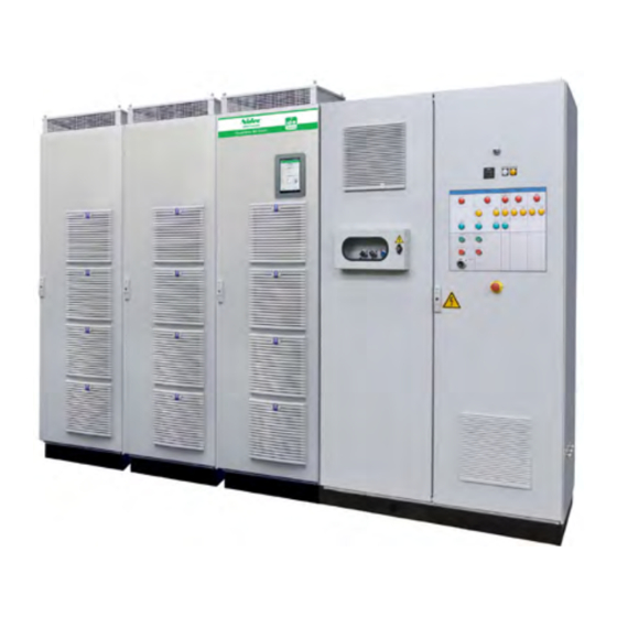
- Page 1 Installation guide Powerdrive MD Smart Equipment MD3 serie High-power free standing drive solution Part number: 5704 en - 2021.10 / b...
- Page 2 NOTE LEROY-SOMER reserves the right to modify the characteristics of its products at any time in order to incorporate the latest technological developments. The information contained in this document is therefore liable to be changed without notice. WARNING For the user’s own safety, this variable speed drive must be connected to an approved earth ( terminal).
- Page 3 SAFETY AND OPERATING INSTRUCTIONS FOR VARIABLE SPEED DRIVES (In accordance with the low voltage directive 2014/35/EU) Throughout the manual, this symbol warns of consequences which can arise from inappropriate use of the drive, since electrical risks can lead to material or physical damage as well as constituting a fire hazard. 1 - General information 5 - Electrical connection When work is performed on variable speed drives that are...
- Page 4 FOREWORD This manual describes the installation of electrical equipment of the Powerdrive MD Smart type. Powerdrive MD Smart Equipment Parameter setting Options According to the electrical plan TH No. located in the cabinet document holder. (these drawings are produced in their entirety by the Electrical design service in accordance with the specification) Gearboxes Motors...
-
Page 5: Table Of Contents
CONTENTS 1 - GENERAL INFORMATION ..........................7 1.1 - General ................................ 7 1.2 - Designation of the equipment ........................7 1.3 - Environmental characteristics ........................7 1.4 - Electrical characteristics ..........................8 1.4.1 - General characteristics............................8 1.4.2 - Electrical characteristics ............................8 1.4.3 - Derating at low frequency ............................ - Page 6 CONTENTS 5 - PARAMETER-SETTING INTERFACE AND OPTIONS ..................28 5.1 - Drive parameter-setting ..........................28 5.1.1 - MD3KEYPAD ..............................28 5.1.2 - IHM Systemiz ..............................30 5.1.3 - Interface architecture............................32 5.1.4 - Special settings ..............................32 5.2 - Add-on options ............................33 5.2.1 - Fieldbus options ..............................
-
Page 7: General Information
GENERAL INFORMATION 1 - GENERAL INFORMATION Nameplate 1.1 - General The Powerdrive MD Smart equipment is one (or more) variable speed drive with very high performance levels that can be used to control: - Induction motors without a speed sensor (open loop mode select ) for applications that do not need rated torque control above 1/10... -
Page 8: Electrical Characteristics
GENERAL INFORMATION 1.4 - Electrical characteristics All work relating to installation, commissioning and maintenance must be carried out by experienced, qualified personnel. 1.4.1 - General characteristics Characteristics Level Power supply voltage • 6P or Multi-Pulses: «T» rating 400V -10% to 480V +10% «TH»... -
Page 9: Derating At Low Frequency
GENERAL INFORMATION 525V to 690 V 3-phase supply Switching frequency = 3 kHz - ambient temperature ≤ 40°C - altitude ≤ 1000 m. Heavy duty Normal duty Imax (3s) Imax (60s) Pout at 525 Pout at 525 Rating Pout at 690V Pout at 690V (kW) (kW) - Page 10 GENERAL INFORMATION INVERTER RECTIFIER 400V RECTIFIER 480V Isp output current Power supply current Power supply current Ambient Rating temperature Normal duty Heavy duty Imax Imax Input Imax Input Imax current current 3kHz 4kHz 6kHz 8kHz 3kHz 4kHz 6kHz 8kHz 40°C 139 130.8 114.6 100.3 110 101.2 88.82 77.36 75TN 50°C...
- Page 11 GENERAL INFORMATION INVERTER RECTIFIER 690V Isp output current Power supply current Ambient Rating temperature Normal duty Heavy duty Imax Input Imax Imax 3s current 3kHz 4kHz 6kHz 8kHz 3kHz 4kHz 6kHz 8kHz 40°C 150TH 50°C 40°C 180TH 50°C 40°C 220TH 50°C 40°C 340TH...
-
Page 12: Mechanical Installation
MECHANICAL INSTALLATION 2 - MECHANICAL INSTALLATION • It is the responsibility of the owner or user to ensure that installation, operation and maintenance of the equipment and its options comply with legislation relating to the safety of equipment and personnel, and with the current regulations in the country of use. -
Page 13: Installation Recommendations
MECHANICAL INSTALLATION W = 400mm Lifting with additional or 600 mm transportation baseplate 60° or 600 + 400 mm mini W = 2x 400mm or 2x 600 mm or 2x 600 + 400 mm 60° mini 2.4 - Installation recommendations Ensure that hot air is not being recycled via the air inlets by leaving sufficient free space at the rear of the equipment or by providing a means of evacuating the hot air expelled by the... -
Page 14: Dimensions
SEE DETAIL OF ROOF 2 NB: The masses, losses and flow rates of the Powerdrive MD Smart equipment are specific to each configuration resulting from the customer’s specifications. To obtain them, please contact Moteurs Leroy-Somer. Installation guide Powerdrive MD Smart Equipment... -
Page 15: Type Of Cooling
MECHANICAL INSTALLATION 2.6 - Type of cooling 2.6.1 - Air cooling Air can exit on all sides of the roof. The drive cabinet can be installed with one side only against a wall (with the IP21 or IP54 roofs). Under no circumstance must the difference between the drive cabinet internal temperature and the ambient temperature outside the cabinet exceed 5°C. -
Page 16: Recommendations
MECHANICAL INSTALLATION To ensure the temperature of the above liquid cooling, a 3-way valve or variable speed pump must be installed. View from behind 3-way valve Note: - The recommended fluid is glycolated water, mix at 25%, the maximum temperature is 40°C. - Salt water is prohibited. -
Page 17: Connections
CONNECTIONS 3 - CONNECTIONS 3.1 - Power connections 3.1.1 - General • All connection work must be performed by qualified electricians in accordance with the laws in force Details of the power connections for the Powerdrive MD Smart in the country where the drive is installed. This includes equipment are given in the Electrical plan THxxxxx. -
Page 18: Power Terminal Block Location
CONNECTIONS 3.1.3 - Power terminal block location Details of the position of various terminal blocks in the cabinet are to be found in the layout sheet of the electrical plan THxxxxx supplied with the cabinet. For wiring details of the Power and control terminal blocks, refer to the "Terminal block" folio. 3.1.4 - Cables and fuses The following characteristics only describe equipment containing one drive. - Page 19 CONNECTIONS AC supply Motor 500-690V - 50Hz Rating Fuses POWERDRIVE Cable cross-section Cable cross-section gG type Overload Ico (A) (mm²) (2) (4) (mm²) (3) (4) Heavy 3x120 + PE 150TH 3x120 + PE Normal 3x120 + PE Heavy 3x120 + PE 180TH 3x120 + PE Normal...
-
Page 20: Connection Of The Control
CONNECTIONS 3.2 - Connection of the control AI1+ Differential analog input 1 (+) • The Powerdrive MD Smart inputs have a positive AI1- Differential analog input 1 (-) logic configuration. Using a drive with a control Factory setting 0-10V speed reference system which has a different control logic may cause ±... - Page 21 CONNECTIONS Analog output Digital output Factory setting 4-20 mA motor current signal Factory setting Zero speed Bipolar analog voltage in common Characteristics Open collector Output type mode or unipolar current in Absolute maximum voltage + 30 V/0 V common mode Overload current 150 mA Resolution...
-
Page 22: Factory Configuration Of Control Terminal Blocks
CONNECTIONS 3.2.3 - Factory configuration of control • Modification of the Run/Stop control logic terminal blocks - For "3-wire" control (jog Run/Stop): In the event of a return to factory settings, the drive will configure its inputs as below. Run FWD Refer to the electrical plan THxxxxx (POWERDRIVE Stop ELECTRICAL folio) to assign correct settings using the... -
Page 23: Sto-1/Sto-2 Inputs: Safe Torque Off Function
CONNECTIONS 3.3 - STO-1/STO-2 inputs: Safe Torque • The line switch integrated as an option in the drive does not isolate the drive input busbars. During the Off function installation and maintenance phases, make sure that the power supply line is disrupted. The STO-1 and STO-2 inputs are safety inputs that can be used to disable the drive output so no torque at the motor 3.3.1 - Single channel locking (SIL1 - PLb) -
Page 24: General Emc - Harmonics - Mains Interference
GENERAL EMC - HARMONICS - MAINS INTERFERENCE 4 - GENERAL EMC - HARMONICS - 4.2 - Radio-frequency interference: Immunity MAINS INTERFERENCE 4.2.1 - General The power structure of frequency inverters leads to the occurrence of two types of phenomenom : The immunity level of a device is defined by its ability to - Low-frequency harmonics fed back to the mains supply operate in an environment which is contaminated by external... -
Page 25: Mains Supply
GENERAL EMC - HARMONICS - MAINS INTERFERENCE 4.4 - Mains supply 4.4.3 - Unbalanced power supply Similar to what is observed on an electric motor, the line 4.4.1 - General current imbalance of a drive operating on an unbalanced Each industrial power supply has its own intrinsic mains supply may be several times the value of the characteristics (short-circuit capability, voltage value and voltage imbalance measured on the power supply. -
Page 26: Basic Precautions For Installation
GENERAL EMC - HARMONICS - MAINS INTERFERENCE 4.5 - Basic precautions for installation These should be taken into account when wiring the 4.5.2 - Wiring outside the cabinet Powerdrive MD Smart and the external components. In 4.5.2.1 - Control wiring each paragraph, they are listed in decreasing order of effect If the control cable needs to run outside the cabinet, use a on correct operation of the installation. -
Page 27: Electromagnetic Compatibility (Emc)
GENERAL EMC - HARMONICS - MAINS INTERFERENCE 4.6 - Electromagnetic compatibility (EMC) CAUTION: Conformity of the drive is only assured when the mechanical and electrical installation instructions described in this manual are adhered to. Immunity Standard Description Application Conformity IEC 61000-4-2 Electrostatic discharges Product casing Level 3 (industrial) -
Page 28: Parameter-Setting Interface And Options
PARAMETER-SETTING INTERFACE AND OPTIONS 5 - PARAMETER-SETTING INTERFACE AND OPTIONS Connection to the drive An AFE type drive includes two control modules: ◦ P1 connector • One module for the active rectifier. The USB-B connector on the door of the Powerdrive MD Smart •... - Page 29 PARAMETER-SETTING INTERFACE AND OPTIONS 5.1.1.2 - Interface architecture • Homepage After the loading phase following power-up of the drive, the parameter setting interface displays the following screen: - Ready state - Locked state - In operation • Local control Gives direct access to the motor control via the display (Start/Stop, direction of rotation, speed reference). This screen can be configured by the user via the menu Parameter-setting/Console configuration.
-
Page 30: Ihm Systemiz
Systemiz application, jointly developed to offer a multitude of services and enrich the user experience. The interactivity of the package provides greater responsiveness, remote or on-site self-diagnosis capability, and easier integration into your systems. To MD3CTLN PB1 CONNECTOR For more informations, visit leroy-somer.fr VARIABLE Downloads Brochures... - Page 31 - Product library: direct access and download any - automatic motor parameter loading (electrical characteris- information available on Nidec Leroy-Somer products, tics and options) in the dedicated drive menu by scanning the - Motor data: electrical data and motor options filled in...
-
Page 32: Interface Architecture
PARAMETER-SETTING INTERFACE AND OPTIONS 5.1.3 - Interface architecture To access the interface main menu page, press the Menu icon in the upper-left corner. Seven menus allow the user to commission and supervise the drive, as described below. - General informations: gives application type and name (if previously set), motor details (if previously set) and drive details. -
Page 33: Add-On Options
PARAMETER-SETTING INTERFACE AND OPTIONS 5.2 - Add-on options 5.2.2 - Speed feedback options The control board of the Powerdrive MD Smart is designed to be plugged with various optional modules. Several options can be combined: • Fieldbus option (see §5.2.1) •... -
Page 34: Braking Modules And Associated Resistors
• Dimensions Braking transistors are only mounted in the factory. * becomes D + 80 from Leroy-Somer offers MD2TF units on their own or combined RF-MD-37500-5 P + 60* with a thermal relay. This must be set to the stated current for upwards the resistor associated with it. -
Page 35: Trips - Diagnostics
TRIPS - DIAGNOSTICS 6 - TRIPS - DIAGNOSTICS 6.3 - Tripping on a safetrip If the drive trips, the drive output bridge is inactive, and the 6.1 - Safety notice drive no longer controls the motor. When a trip is active, the LEDs present on the control board The user must not attempt to repair the drive display alternately “t.r.”... - Page 36 TRIPS - DIAGNOSTICS Parameter-setting Reason for trip Solution interface name • Check the motor insulation. • Check the motor cables (connections and insulation). Over current • Check the quality of the mains supply. Over current • Run power diagnostics. This trip cannot be reset for a period of 10 seconds. •...
- Page 37 TRIPS - DIAGNOSTICS Parameter-setting Reason for trip Solution interface name • Check the ambient temperature around the motor. Opening of the PTC input of the PX1 • Check that the motor current is less than the stated terminal block or T1 and T2 inputs of the Motor PTC current.
- Page 38 TRIPS - DIAGNOSTICS Parameter-setting Reason for trip Solution interface name The DO2 output load current (MDX-I/O DO2 MDX-I/O over Check that DO2 is not short-circuited. option) is >200 mA The DO3 output load current (MDX-I/O DO3 MDX-I/O over Check that DO3 is not short-circuited. option) is >200 mA Communication problem between the Check the MDX-I/O option mounting.
-
Page 39: Maintenance
MAINTENANCE 7 - MAINTENANCE • Servicing • All work relating to installation, commissioning Printed circuits and drive components do not normally maintenance must carried require any maintenance. Contact your vendor or the nearest experienced, qualified personnel. approved repair company in the event of a problem. •... - Page 40 *40041752* Moteurs Leroy-Somer Headquarter: Boulevard Marcellin Leroy - CS 10015 16915 ANGOULÊME Cedex 9 Limited company with capital of 38,679,664 € RCS Angoulême 338 567 258 www.leroy-somer.com...
Need help?
Do you have a question about the LEROY-SOMER and is the answer not in the manual?
Questions and answers