Nidec Commander C200 Step-By-Step Manual
Hide thumbs
Also See for Commander C200:
- Power installation manual (110 pages) ,
- Step-by-step manual (63 pages) ,
- Step-by-step manual (14 pages)
Advertisement
Table of Contents
- 1 Features of the Drive
- 2 STEP 1: Check the Contents of the Box
- 3 STEP 3: Mount the Drive
- 4 Power and Ground Connections
- 5 Control Connections
- 6 STEP 7: Use the Keypad
- 7 STEP 8: Run the Motor
- 8 Additional Information Troubleshooting
- 9 Status Indicators
- 10 Appendix A UL Listing Information
- 11 Motor Overload Protection and Thermal Memory Retention
- 12 Modular Drive Systems
- 13 Requirement for Transient Surge Suppression
- Download this manual
Advertisement
Table of Contents

Related Manuals for Nidec Commander C200


Summary of Contents for Nidec Commander C200
- Page 1 Commander C200/C300 Step By Step Guide Guide pas à pas Schritt-für-Schritt-Anleitung Guida dettagliata Guía detallada Frame sizes 5 to 9 Tailles 5 à 9 Baugrößen 5 bis 9 Taglie da 5 a 9 Tamaños 5 a 9...
-
Page 2: Features Of The Drive
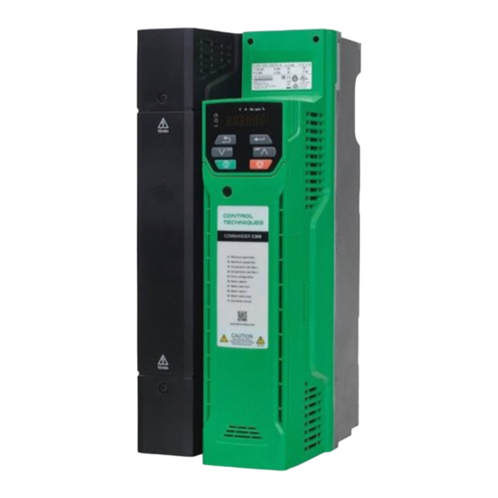
English Introduction The Commander C200 and C300 is a simple and flexible range of drives from 0.25 kW to 132 kW in 9 frame sizes and two input voltage ranges (200 V, and 400 V). This Step-by Step guide provides simple step-by-step instructions on how to mount the drive, fuse and cable selection, wiring the drive-up, programming the drive and running the motor in analog input mode or keypad mode on frames 5 to 9. -
Page 3: Step 1: Check The Contents Of The Box
E - AC in AC out (without internal choke) Current Rating : Voltage rating Heavy Duty current rating x10 2 - 200 V (200 - 240 ± 10 %) 4 - 400 V (380 - 480 ± 10 %) Commander C200/C300 Step By Step Guide Issue Number: 2... -
Page 4: Step 3: Mount The Drive
(11.42 in) (101.4 Ib) 1090 mm 1108 mm 259 mm 310 mm 290 mm 66.5 kg 9.0 mm (0.35 in) (42.91 in) (43.62 in) (10.20 in) (12.21 in) (11.42 in) (146.6 Ib) Commander C200/C300 Step By Step Guide Issue Number: 2... - Page 5 IEC cable sizes assume Copper conductor, PVC insulation, Installation method B2 and ambient NOTE temperature of 40 °C (104 °F). UL cable sizes assume Copper conductor with insulation rated at 75 °C (167 °F). Commander C200/C300 Step By Step Guide Issue Number: 2...
- Page 6 STEP 5: Remove the terminal cover and finger guard breakouts Using a flat bladed screwdriver, turn the terminal cover locking clip anti-clockwise by approximately 30°. Slide the terminal cover down. Remove terminal cover in direction shown. Commander C200/C300 Step By Step Guide Issue Number: 2...
- Page 7 Power and ground terminals 6.0 N m (4.4 lb ft) Power and ground terminals 12 N m (8.85 lb ft) 8 and 9 Power and ground terminals 15 N m (11.1 lb ft) Commander C200/C300 Step By Step Guide Issue Number: 2...
-
Page 8: Power And Ground Connections
The lower terminal block (2) is used for Motor connection. On size 5, the supply and motor ground connections are made using the M5 studs located near the plug-in power connector. Refer to Figure 6-1. Commander C200/C300 Step By Step Guide Issue Number: 2... - Page 9 Supply Supply Ground On a size 6, the supply and motor ground connections are made using the M6 studs located above the supply and motor terminals. Refer to Figure 6-2. Commander C200/C300 Step By Step Guide Issue Number: 2...
- Page 10 Optional ground connection On size 7 and 8, the supply and motor ground connections are made using the M8 studs located by the supply and motor connection terminals. Refer to Figure 6-3. Commander C200/C300 Step By Step Guide Issue Number: 2...
- Page 11 Motor Optional ground connection On size 9A, the supply and motor ground connections are made using the M10 studs located by the supply and motor connection terminals. Refer to Figure 6-4. Commander C200/C300 Step By Step Guide Issue Number: 2...
-
Page 12: Control Connections
Half of the cross-sectional area of the input phase conductor > 35 mm² Control connections The control terminals are configured by default for the arrangement shown below: Figure 6-5 Commander C200/C300 control terminal connections Digital I/O Analog I/O 24 V user... -
Page 13: Step 7: Use The Keypad
To enter Edit Mode, press button Holding increases or decreases value 0.00 Edit Mode (edited digit flashes) Commander C200/C300 Step By Step Guide Issue Number: 2... -
Page 14: Step 8: Run The Motor
The drive is now ready to run the motor. Set Pr 05 to 'PAd'. Close enable (C200) or Safe Torque Off (C300). Press the start key Increasing and Press the up and down keys to increase and decrease the speed. decreasing speed Stopping Press the Stop/Reset key Commander C200/C300 Step By Step Guide Issue Number: 2... -
Page 15: Additional Information Troubleshooting
400V drive Def.50: 400 V 400V drive Def.60: 460 V Motor Rated Power Factor 0.00 to 1.00 0.85 Refer to the Control User Guide for further User Security Status LEVEL.1 information Commander C200/C300 Step By Step Guide Issue Number: 2... -
Page 16: Appendix A Ul Listing Information
Drives must be installed using cables rated for 75 °C operation, copper wire only. Where possible, UL Listed closed-loop connectors sized according to the field wiring shall be used for all field power wiring connections. Commander C200/C300 Step By Step Guide Issue Number: 2... -
Page 17: Motor Overload Protection And Thermal Memory Retention
AND SHALL BE RATED 575 Vac (PHASE TO GROUND), 575 Vac (PHASE TO PHASE), SUITABLE FOR OVERVOLTAGE CATEGORY III, AND SHALL PROVIDE PROTECTION FOR A RATED IMPULSE VOLTAGE TO WITHSTAND VOLTAGE PEAK OF 6 kV AND A CLAMPING VOLTAGE OF MAXIMUM 2400 V. Commander C200/C300 Step By Step Guide Issue Number: 2...
Need help?
Do you have a question about the Commander C200 and is the answer not in the manual?
Questions and answers