
Related Manuals for Nidec NE200 Series


Summary of Contents for Nidec NE200 Series
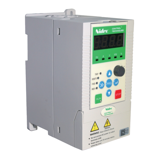
- Page 1 Quick Start Guide NE200/NE300 Variable Speed AC drive Part Number:31019007 www.drive-setup.com...
- Page 2 NE200&300 Quick Start Guide Revision History Date Version Description 2020/4/7 Issued for the first time 2020/5/19 Add “Modbus Address” column in parameter brief list...
- Page 3 NE200&300 Quick Start Guide 1. Safety Precautions 1.1 Description of safety marks Warning: A Warning contains information which is essential for avoiding a safety hazard. Caution: A Caution contains information which is necessary for avoiding a risk of damage to the product or other equipment. 1.2 Use Warning ...
- Page 4 NE200&300 Quick Start Guide control cabinet shall be equipped with fan and ventilation port. And ducts for radiation shall be constructed in the cabinet. 1.4 Wiring Warning The wiring must be conducted by qualified electricians. Otherwise, there exists the risk of electric shock or inverter damage.
- Page 5 NE200&300 Quick Start Guide the inverter failure caused by the over-current of the distribution capacitor. The inverter which equipped with DC reactor must connect with DC reactor between the terminal of P1、(+) otherwise the inverter will not display after power on. 1.5 Operation Warning ...
- Page 6 NE200&300 Quick Start Guide damage of the mechanical equipment. In the applications with mains frequency and variable frequency switching, the two contactors for controlling the mains frequency and variable frequency switching shall be interlocked. 1.6 Maintenance & Inspection Warning ...
- Page 7 NE200&300 Quick Start Guide 2. Introduction to NE200&300 2.1 Product Model Description The digits and letters of the inverter model number on the nameplate indicate information such as product series, voltage grade, power ratings and hardware versions. 0022 Product Series Structure Code NE200 None Standard...
- Page 8 NE200&300 Quick Start Guide 2.3 Product Series 2.3.1 NE200 Product Series NE200−4T□□□□GB Three-phase 400V Constant torque/heavy-duty application Power ( kW ) 0.75 Adapted motor (kW) 0.75 Voltage (V) 3phase 0~rated input voltage Rated current (A) Output Overload 150% 1min; 180% 20sec. capability Rated voltage/ 3phase 380V/440V;...
- Page 9 NE200&300 Quick Start Guide NE200−2S□□□□GB Single-phase 220V constant torque/heavy duty application Power ( kW ) 0.75 Adapted motor (kW) 0.75 Voltage (V) 3phase 0~rated input voltage Rated current (A) Output Overload 150% 1min; 180% 20sec. capability Rated voltage/ 1phase 200V/240V; 50Hz/60Hz frequency 176V~264V;...
- Page 10 NE200&300 Quick Start Guide 2.3.2 NE300 Product Series NE300−4T□□□□GB Three-phase 400V Constant torque/heavy-duty application * NE300−4T1600G-F and above products are equipped with in-built DC reactor as standard.
- Page 11 NE200&300 Quick Start Guide NE300−4T□□□□PB Three-phase 400V Variable torque/normal-duty application * NE300−4T1850P-F and above products are equipped with external DC reactor as standard.
- Page 12 NE200&300 Quick Start Guide 3. Product Installation 3.1 NE200 Product Outline, Mounting Dimension(Unit:mm) Fig.3-1 Product Outline, Mounting Dimension Schematic diagram Note: NE200 series support 35mm DIN-rail mounting. Inverter Model NE200-2S0004GB NE200-2S0007GB NE200-2S0015GB NE200-4T0007G/0015PB NE200-4T0015G/0022PB NE200-4T0022GB-M NE200-2S0022GB NE200-4T0022G/0040PB NE200-4T0040G/0055PB NE200-2S0004GB Note:...
- Page 13 NE200&300 Quick Start Guide 3.2 NE300 Product Outline, Mounting Dimension(Unit:mm) Fig.3-2 Product Outline, Mounting Dimension Schematic diagram Inverter Model NE300-4T0015G/0022PB NE300-4T0022G/0040PB NE300-4T0040G/0055PB NE300-4T0055G/0075PB NE300-4T0075G/0110PB NE300-4T0110G/0150PB NE300-4T0150G/0185PB NE300-4T0185G/0220PB NE300-4T0220G/0300PB NE300-4T0300G/0370P NE300-4T0370G/0450P NE300-4T0450G/0550P NE300-4T0550G/0750P NE300-4T0750G/0900P NE300-4T0900G/1100P NE300-4T1100G/1320P...
- Page 14 NE200&300 Quick Start Guide Inverter Model NE300-4T1320G/1600P-U NE300-4T1320G/1600P-D NE300-4T1600G/1850P-U NE300-4T1600G/1850P-D NE300-4T1850G/2000P-U NE300-4T1850G/2000P-D NE300-4T2000G/2200P-U NE300-4T2000G/2200P-D NE300-4T2200G/2500P-U NE300-4T2200G/2500P-D NE300-4T2500G/2800P-U NE300-4T2500G/2800P-D NE300-4T1600G/1850P-F NE300-4T1850G/2000P-F 1400 1400 1270 NE300-4T2000G/2200P-F NE300-4T2200G/2500P-F NE300-4T2500G/2800P-F NE300-4T2800G/3150P-F 1600 1600 1460 NE300-4T3150G/3550P-F NE300-4T3550G/4000P-F NE300-4T4000G/4500P-F 1800 1800 1630 NE300-4T4500G/5000P-F NE300-4T5000G/5600P-F NE300-4T5600G/6300P-F NE300-4T6300G/7100P-F 2000 1000 2000...
- Page 15 NE200&300 Quick Start Guide * This model consisting of two separate models, 1560 is the net dimension without mounting distance. Must keep ≥ 200 mounting distance between them. 3.3 Operating keypad panel outline and mounting dimensions (Unit:mm) Fig.3-3 Operating Panel Outline and Mounting Dimension 3.4 Keypad holder outline and mounting dimensions NEF-KB01 is the mounting tray when the operation panel is to install on the electric control cabinet.
- Page 16 NE200&300 Quick Start Guide 4 Wiring of Inverter 4.1 Terminal Wiring of NE200 Fig. 4-1 Terminal Wiring(0022GB~0040GB)...
- Page 17 NE200&300 Quick Start Guide 4.1.1 Functions of Control Circuit Terminals Standard configuration of control circuit terminals Termina Type Terminal function Technical specification Optical-isolator input Multi-functional input X1 ~ X5 Frequency range: : 0 ~ 200Hz terminals 1 ~ 5 Voltage range: 0 ~ 12V Digital Optical-isolator output input...
- Page 18 NE200&300 Quick Start Guide Termina Type Terminal function Technical specification Rate: 1200/2400/4800/9600/19200/384 00bps; 485+ 485 differential positive Max. parallel 127 No.s; SW3 RS485 select adapted resistor; Max. Length 500m. (twisted shielding cable) 485- 485 differential negative 485 shielding grounding Internal isolated with COM NE200-2S0022GB~ NE200-4T0040G/0055PB NE200-2S0004GB~...
- Page 19 NE200&300 Quick Start Guide 4.2 Terminal Wiring of NE300 Fig.4-3 Terminal Wiring (0220G/0300PB as example...
- Page 20 NE200&300 Quick Start Guide 4.2.1 Functions of Control Circuit Terminals Standard configuration of control circuit terminals Termina Type Terminal function Technical specification Optical-isolator input Multi-functional input ~ Frequency range: : 0 ~ 200Hz terminals 1 ~ 3 Voltage range: 0 ~ 24V Multi-functional input :...
- Page 21 NE200&300 Quick Start Guide Termina Type Terminal function Technical specification Analog grounding Internal isolated with COM 0 ~ 20mA: Allow output impedance 200~500Ω 0 ~ 10V: Allowed output Analog output 1 impedance ≥10kΩ. Analog With SC protection; 0~20mA or output 0~10V analog output can be selected through DIP switch SW2 Analog grounding...
- Page 22 NE200&300 Quick Start Guide 5. Operation and Display Fig.5-1 Operation Panel Diagram 5.1 Keyboard button description Table 5-1 Keyboard keys description Keys Name Function Programming key Entry and exit of primary menu Enter the next level menu or confirm the data ENTER Confirmation key setting...
- Page 23 NE200&300 Quick Start Guide 5.2 Instruction of function code viewing and modification The operation panel of the NE200&300 inverter adopts three levels menu structure to carry out operations such as parameter setting. The three levels are: Groups of function code (level-1 menu) Function code (level-2 menu) Function code setup value(level-3 menu) Note:...
- Page 24 NE200&300 Quick Start Guide 6. Run the motor Operations Details Before power-on Check: No operating signal. The motor has been connected. 1 phase 220V/ 3 phase 380V input power has been connected correctly. inverter Confirm the inverter displays the correct operating powered on mode on power -up.
- Page 25 NE200&300 Quick Start Guide 7. List of Parameters Attention: “○”means the parameter can be changed during running. “×”means the parameter cannot be changed during running; “*” means the parameter is detected value or fixed value and not changeable. “-” means manufacturer parameter and the users have no access to it. ②...
- Page 26 NE200&300 Quick Start Guide Modbus Code Description Setting range Default Modify Address 3: PULSE setup 4: Communication 5:MS (Multi-step) Speed 6: PLC 7: PID 8: Keypad potentiometer 1: Al1 2: Al2 3: PULSE setup Frequency 4: Communication F0.04 reference2 ○ 0104H 5:MS (Multi-step) Speed (Freq.
- Page 27 NE200&300 Quick Start Guide Modbus Code Description Setting range Default Modify Address selection 1: Be saved in power failure 2: Be cleared to 0 after stop Basic 0.10 ~ 550.0Hz F0.10 50.00Hz × 010AH frequency MAX[50.00Hz, Freq. F0.11 upper limit, Reference 50.00Hz ×...
- Page 28 NE200&300 Quick Start Guide Modbus Code Description Setting range Default Modify Address 0: Start directly ③ 1: DC injection brake first Start mode ○ 0200H and then start at start freq. 2: Speed tracking and start F1.01 Start freq. 0.10~60.00Hz 0.50Hz ○...
- Page 29 NE200&300 Quick Start Guide Modbus Code Description Setting range Default Modify Address Type G: 0.0~100.0% rated ③ DC brake current 0.00% ○ 020BH current at stop Type P: 0.0~80.0% rated current DC brake time 0.0 ~ 30.0s F1.12 0.0s ○ 020CH at stop Energy...
- Page 30 NE200&300 Quick Start Guide Modbus Code Description Setting range Default Modify Address F2.00 Jog running freq. 0.0 ~ 50.00Hz 5.00Hz ○ 0300H ② ② 0.1 ~ 360.0s 6.00s ③ ③ F2.01 Jog Acc. time ○ 0301H 0.0~3600.0s 20.0s ② ② 0.1 ~...
- Page 31 NE200&300 Quick Start Guide Modbus Code Description Setting range Default Modify Address Energy-saving 1: Enable control select 0: Disabled 1: Enabled F2.17 AVR Function 2: Disabled only at × 0311H speed-down F2.18 Over modulation 0: Enabled 1: Disabled × 0312H ③...
- Page 32 NE200&300 Quick Start Guide Modbus Code Description Setting range Default Modify Address 0: Asynchronous modulation High freq. F2.29 × 031DH modulation mode 1: Synchronous modulation IO output Freq. 0: According to the Freq. baseline select after ACC/DEC speed F2.31 ○ 031FH while vector 1: According to the...
- Page 33 NE200&300 Quick Start Guide Modbus Code Description Setting range Default Modify Address proportional gain 2 Speed loop integral F3.04 1~3000 ○ 0404H time 2 Switching 0.0 ~ 60.00Hz F3.05 10.00Hz ○ 0405H frequency 2 ② Speed loop filter ③ 0 ~ 500ms F3.06 ○...
- Page 34 NE200&300 Quick Start Guide Modbus Code Description Setting range Default Modify Address speed limit setting(F3.13) 1: AI1 2: AI2 PULSE communication 5: keypad potentiometer Torque control 0.00 ~ 550.0Hz F3.13 speed limit digital 50.00Hz ○ 040DH setting ③ Encoder pulse F3.14 1~9999 1000...
- Page 35 NE200&300 Quick Start Guide Modbus Code Description Setting range Default Modify Address total modulation Torque limit in F3.26 vector control 0~300.0% 150.0% ○ 041AH mode Torque boost cut-off frequency in F3.27 0.00~15.00Hz 12.00Hz ○ 041BH torque control mode Torque boost F3.28 amount in torque 0.0~20.0%...
- Page 36 NE200&300 Quick Start Guide Modbus Code Description Setting range Default Modify Address coefficient Flux weaken regulation F3.39 0~3000 1500 ○ 0427H integration coefficient Synchronous motor F3.40 low speed Min. 0~100% ○ 0428H current Synchronous motor F3.41 low speed carrier 1.0~16.0KHz 2.0KHz ○...
- Page 37 NE200&300 Quick Start Guide Modbus Code Description Setting range Default Modify Address 3: 1.2 power decreasing torque 4: Multiple dots V/F 0.0 ~ F4.03 F4.01 V/F freq. F1 10.00Hz × 0501H V/F voltage 0.0 ~ 100.0% F4.02 20.00% × 0502H F4.01 ~...
- Page 38 NE200&300 Quick Start Guide Modbus Code Description Setting range Default Modify Address separation voltage rising time Depends V/F oscillation F4.14 0~500 ○ 050EH suppression model Group F5: Motor Parameters Modbus Code Description Setting range Default Modify Address 0: Common asynchronous motor 0600H F5.00 motor type...
- Page 39 NE200&300 Quick Start Guide Modbus Code Description Setting range Default Modify Address ③ 1 ~ 65535mΩ(Drive rated 0606H Stator Depends power≤22kW) resistance ○ 0.1 ~ 6553.5mΩ(Drive model rated power>22kW) ② Leakage Depends 0.01 ~ 655.35mH inductive ○ 0607H reactance X model ③...
- Page 40 NE200&300 Quick Start Guide Modbus Code Description Setting range Default Modify Address ③ 1 ~ 65535mΩ(Drive rated Depends Synchronous power≤22kW) ○ 060BH 0.1 ~ 6553.5mΩ(Drive motor stator model resistor Rs rated power>22kW) ② Synchronous Depends 0.01 ~ 655.35mH F5.12 motor D-axis ○...
- Page 41 NE200&300 Quick Start Guide Modbus Code Description Setting range Default Modify Address 3: Three-wire mode 2 X1 terminal 0: NULL F6.01 Function 1: FWD × 0701H selection 2: REV 3: RUN X2 terminal 4: F/R direction F6.02 Function × 0702H 5: HLD self-hold selection 6: FWD jog run...
- Page 42 NE200&300 Quick Start Guide Modbus Code Description Setting range Default Modify Address 23: Acc./Dec. time terminal selector 2 function 24: Running pause selection ② normally open Reserve ③ 25: Running pause normally closed F6.09 Reserved × terminal 26: External fault function normally open selection...
- Page 43 NE200&300 Quick Start Guide Modbus Code Description Setting range Default Modify Address 41: Actual length clear 42: FWD running (FWD NC) 43: REV running (REV 44: HLD (Normally open) 45: Increase torque 46: Torque increment clear 47: Decrease torque 48: One key recover user parameters(Valid in stop state) 49~56: Reserved...
- Page 44 NE200&300 Quick Start Guide Modbus Code Description Setting range Default Modify Address AI2 Max. input -200.0 ~ 200.0% F6.19 corresponding 100.00% ○ 0713H setup AI2 input filter 0.01 ~ 50.00s F6.20 0.05s ○ 0714H time PULSE Min. 0.00 ~ F6.23 F6.21 0.00kHz ○...
- Page 45 NE200&300 Quick Start Guide Modbus Code Description Setting range Default Modify Address terminal open Pos. logic of Xi terminal: Be valid while connecting between Xi and COM. Neg. logic of Xi terminal: Be valid while Pos. and Neg. disconnecting F6.32 logic terminal 0000 ×...
- Page 46 NE200&300 Quick Start Guide Modbus Code Description Setting range Default Modify Address Thousands: Logic of X8 terminal Note: Terminal 24 、 25 、 26 、 27 、 42 、 43 、 44 and 49 are not impacted by this parameter. Group F7: Output terminal Modbus Code...
- Page 47 NE200&300 Quick Start Guide Modbus Code Description Setting range Default Modify Address 17: Under voltage status output 18: Drive overload pre-warning 19: Fixed-length arrived, level signal 20: PID in dormancy 21: AI1>AI2 22: AI1<F7.16 23: AI1>F7.16 F7.16<AI1<F7.17 25: Frequency lower limit arrival 26: Multi-pumps system auxiliary...
- Page 48 NE200&300 Quick Start Guide Modbus Code Description Setting range Default Modify Address ③ Frequency 0.00 ~ 320.0Hz detection value 25.00Hz ○ 0808H 2 (FDT2 level) Freq. detection 0.00 ~ 10.00Hz F7.09 1.00Hz ○ 0809H lag2 (FDT2-lag) Up detection 0.00 ~ 550.0Hz F7.10 50.00Hz ○...
- Page 49 NE200&300 Quick Start Guide Modbus Code Description Setting range Default Modify Address 4: Output voltage (0 ~ Max Voltage) 5: PID setup (0 ~ 10V) 6: PID feedback (0 ~ 10V) ② Y1 function 7: Calibrating signal ○ 0815H (5V) definition 8: Output torque (0 ~...
- Page 50 NE200&300 Quick Start Guide Modbus Code Description Setting range Default Modify Address ② Y1 Max. Y1 Min. output pulse 081AH output pulse freq. ~ 50.00kHz freq. ③ F7.26 10.00kHz ○ DO Max. DO 最小输出脉冲频 081AH output pulse 率~ 50.00kHz freq. ②...
- Page 51 NE200&300 Quick Start Guide Modbus Code Description Setting range Default Modify Address datum Units: Logic of Y1 terminal ② Digital output Tens: Reserve terminal Hundreds: Logic of 0000 ○ 0824H Pos./Neg. logic Relay 1 Thousands: Reserve F7.36 Units: Logic of Y1 0824H terminal ③...
- Page 52 NE200&300 Quick Start Guide Modbus Code Description Setting range Default Modify Address Analog PID 0.0 ~ 999.9 F8.02 ○ 0902H digital setup Analog closed 1.0 ~ 999.9 F8.03 loop measuring ○ 0903H range PID action 0: Positive F8.04 ○ 0904H direction 1: Negative PID proportional...
- Page 53 NE200&300 Quick Start Guide Modbus Code Description Setting range Default Modify Address ② PID output 0.0~320.0Hz ③ F8.16 50.00Hz ○ 0910H 0.0 ~ 600.0Hz positive limit PID output 0.00 ~ 550.0Hz F8.17 0.00Hz ○ 0911H negative limit 0.00 ~ 550.0Hz F8.18 PID preset freq.
- Page 54 NE200&300 Quick Start Guide Modbus Code Description Setting range Default Addres 0.00 ~ Max frequency F9.04 Multi-step freq.5 30.00 Hz ○ 0A04H 0.00 ~ Max frequency F9.05 Multi-step freq.6 40.00 Hz ○ 0A05H 0.00 ~ Max frequency F9.06 Multi-step freq.7 50.00 Hz ○...
- Page 55 NE200&300 Quick Start Guide Modbus Code Description Setting range Default Addres Step T2 program 1 F/r ~ 4 F/r F9.19 ○ 0A13H running setting Step T3 program 1 F/r ~ 4 F/r F9.20 ○ 0A14H running setting Step T4 program 1 F/r ~...
- Page 56 NE200&300 Quick Start Guide Modbus Code Description Setting range Default Addres Freq.7 selection potentiometer 4: Pulse input Group FA: Wobble Frequency Modbus Code Description Setting range Default Modify Address Wobble FA.00 0.0~50.0% 0.0% ○ 0B00H amplitude FA.01 Jitter frequency 0.0~50.0%(to FA.00) 0.0% ○...
- Page 57 NE200&300 Quick Start Guide Modbus Code Description Setting range Default Modify Address protection mode 1: Common motor (with low speed compensation) 2: Variable frequency motor (without low speed compensation) Electro thermal 20 ~ 110% FC.01 100% ○ 0D01H protection value Overload 30.0 ~...
- Page 58 NE200&300 Quick Start Guide Modbus Code Description Setting range Default Modify Address 1 ~ 100% Input phase loss FC.08 (100% correspond × 0D08H detection to 800V) Input phase loss 2 ~ 255s FC.09 detection delay × 0D09H time Output phase loss FC.10 1: Valid ○...
- Page 59 NE200&300 Quick Start Guide Modbus Code Description Setting range Default Modify Address 0: Warning and Treatment select running still FC.19 while overvoltage ○ 0D13H 1: Fault cause forewarning stopping Reminding or not 0: Yes ○ 0D14H FC.20 while 1: No undervoltage Group Fd: Communication Parameters Modbus...
- Page 60 NE200&300 Quick Start Guide Modbus Code Description Setting range Default Modify Address 0: Time interval between 2 packets Communication receiving. Fd.07 interrupt ○ 0E07H 1: Time interval of detection mode 0005H Add. data writing Feedback or not (Y or N) 0 :...
- Page 61 NE200&300 Quick Start Guide Modbus Code Description Setting range Default Modify Address control mode 2: Valid in Fault state of terminal/ communication control mode 3: Valid in both stop & fault state of terminal/ communication control mode 0: No display Running 1: Display at stop freq.(Hz)
- Page 62 NE200&300 Quick Start Guide Modbus Code Description Setting range Default Modify Address 0: No display 1: Display at stop Output torque FE.09 ○ 0F09H 2: Display at running 3: Display at stop & running 0: No display 1: Display at stop Reference FE.10 torque (%...
- Page 63 NE200&300 Quick Start Guide Modbus Code Description Setting range Default Modify Address 2: Display at running 3: Display at stop & running 0: No display 1: Display at stop Analog PID FE.17 ○ 0F11H 2: Display at running setup 3: Display at stop & running 0: No display 1: Display at stop...
- Page 64 NE200&300 Quick Start Guide Modbus Code Description Setting range Default Modify Address 0: NULL 1: Uu1 bus undervoltage 2: OC1 Acc. overcurrent 3: OC2 Dec. overcurrent 4: OC3 Constant speed overcurrent 5: Ou1 Acc. overvoltage 6: Ou2 Dec. overvoltage 7: Ou3 overvoltage in constant speed ②...
- Page 65 NE200&300 Quick Start Guide Modbus Code Description Setting range Default Modify Address 21: IDE Hall current detection fault 22: ECE PG fault 23: LC fast current limit fault 24: EF2 terminal close fault 25: PIDE: PID feedback offline 26: OLP2 Forewarning of overload fault 27: InPE Initial position fault detected of...
- Page 66 NE200&300 Quick Start Guide Modbus Code Description Setting range Default Modify Address FF.10 Reserved Reserved Reserved 100AH Software version FF.11 1.00~10.00 100BH number of control board Non-standard version FF.12 0~255 100CH number of software ② Heat sink -30.0 ~ 120.0°C 0.0°C 100DH temperature...
- Page 67 NE200&300 Quick Start Guide Modbus Code Description Setting range Default Modify Address 2: All parameters aren’t allowed read 0: No operation Parameter FP.02 1: Clear fault history × initialization 2: Restore to defaults 0: No action 1: Parameters download 2: Parameters Parameter FP.03 ×...
- Page 68 8. Trip information and trouble shooting Once a trip is detected, NE200&300 would immediately block PWM output and enter the trip protection state; meanwhile TRIP on the keyboard would spark and the LED display the trip code. At this point one must identify the cause of trip and its corresponding solutions according to the method suggested in this section, if it does not work, please contact us immediately.
- Page 69 Trip Trip Type Possible causes Solutions code closed-loop vector control 1.Acceleration time 1. Increase the acceleration too short time Over Voltage in Acceleration 2.Power supply 2. Check the input power abnormal source. 1.Deceleration time 1. Increase the deceleration too short time Over voltage in deceleration...
- Page 70 Trip Trip Type Possible causes Solutions code 3.The Curve of V/F 3. Adjust the V/F curve and is not fit torque boosting performance. 4. Motor always 4. Use specialized electric works with heavy motor. load at low speed. 5. Motor blocked to 5.
- Page 71 Trip Trip Type Possible causes Solutions code error 2. Ask for service from 2. EEPROM supplier damaged Keypad & 1.Connection cable 1. Check the connection control board between keyboard cable between keyboard and communication and control panel is control panel interrupted broken 1.The braking line or...
- Page 72 Trip Trip Type Possible causes Solutions code inverter direction. 1. Load too large or 1. Decrease the load and motor blocked to check motor and mechanical stall part status Fast current limit 2. Inverter power 2. Choose higher power fault rating too small inverter 3.
- Page 73 Hazardous substance limit table for electrical and electronic products Hazardous substances Hexavalent Polybrominated Polybrominated Part Name Lead Mercury Cadmium Chromium biphenyls diphenyl ethers (Pb) (Hg) (Cd) (Cr +6) (PBB) (PBDE) Electronics assembly Housing assembly Keypad Battery This table is in accordance with the provision of SJ/T11364 O: Indicates that said hazardous substance in all of the homogeneous materials for this part is below the limit requirement of GB/T 26572 X: Indicates that said hazardous substance contained in at least one of the homogeneous...
Need help?
Do you have a question about the NE200 Series and is the answer not in the manual?
Questions and answers
Showing Hardware error
A hardware error on the Nidec NE200 Series indicates issues such as encoder faults (e.g., reversed or damaged encoder signal wires, incorrect encoder direction), hall current detection faults (IDE), fast current limit faults (LC), terminal close faults (EF2), heatsink overheat (OH1), motor or drive overload (OL1, OL2), EEPROM faults (EEP), and other component failures like brake unit faults (bCE) or input/output phase failures (SP1, SPO). These errors are related to physical components being damaged, miswired, or operating outside safe limits.
This answer is automatically generated
Como puedo aumentar la velocidad lenta?
To increase the speed of the Nidec NE200 Series, you can:
1. Increase the proportional gain or reduce the integration time of the speed regulator. This will accelerate the dynamic response of the speed loop. However, be careful not to set the gain too high or the integration time too short, as it may cause system oscillation.
2. Adjust the VC slip compensation (F3.09). If the motor speed is lower than the target speed under load, increase this value to maintain a constant motor speed.
3. Set the frequency resolution (F2.27) to 0.1 Hz if higher maximum running frequency is needed (up to 3200.0 Hz).
4. Ensure the inverter power rating is sufficient. If it is too small, choose a higher capacity drive.
5. Make sure the acceleration time is properly set (F2.28) to allow the motor to reach higher speeds without triggering faults.
This answer is automatically generated
How to adjust the rpm
To adjust the RPM on a Nidec NE200 Series motor, follow these steps:
1. Set motor-related parameters based on the motor nameplate, including motor type, rated current, motor polarity, and rated rotation speed.
2. Set the control mode to closed-loop control by setting parameter F0.01 = 2.
3. If using a resolver encoder (F3.46 = 3), configure encoder-related parameters F3.47 to F3.50.
4. Perform a rotary auto-tune with the motor disconnected from the load.
5. Ensure the rated rotation speed you set is lower than the motor's synchronous speed, calculated as (120 × frequency) / number of poles.
6. If the encoder has no Z signal, set the encoder pulse manually and run the motor in open loop at 50 Hz to verify motor speed.
Adjusting RPM can also involve changing frequency references using PID settings or AI inputs, such as setting PID preset frequency (F8.18).
This answer is automatically generated
Why RPM is not fixing why rpm is reducing
The RPM in the Nidec NE200 Series may decrease due to several reasons:
1. Incorrect Encoder Pulse Quantity – If the pulse quantity of the encoder is not set correctly, the motor operation may become abnormal.
2. PG Reduction Ratio Setting (F3.15) – If the PG (pulse generator) is not mounted directly on the motor axle, the reduction ratio must be set correctly. An incorrect setting may cause speed reduction.
3. PG Direction Setting (F3.16) – If the feedback direction is incorrect, the encoder feedback may cause the drive to adjust speed improperly. Changing this setting can correct the issue.
4. Acceleration/Deceleration Settings – The drive has predefined acceleration and deceleration times. If deceleration time is triggered or incorrectly set, the RPM may decrease.
5. CAN Communication Issues – If the control signals from the CAN system indicate a fault, direction change, or speed adjustment, this can lead to a decrease in RPM.
Checking and correcting these parameters should help maintain the desired RPM.
This answer is automatically generated