Table of Contents
Advertisement
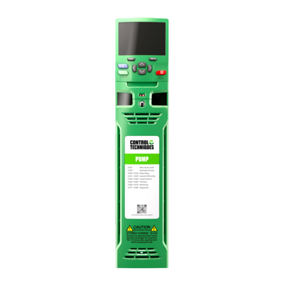
Pump drive F600
Step By Step Guide
Frame sizes 3 to 11
Diese Anleitung bietet Informationen für eine schnelle Inbetriebnahme eines einfachen Umrichter-Motor-Systems.
This guide provides a fast and simple start-up procedure for a basic drive and motor installation.
Bei aufwendigeren Systemen: Umfassende Betriebsanleitungen, Online-Videos und Hilfsmittel finden Sie unter
For help with more advanced installations: Comprehensive user guides, online videos and help tools can be
unserer Webadresse oder über den vorstehenden QR-Code.
EN
DE
accessed using the web address or QR code above.
Bitte lesen Sie die dem Umrichter beiliegende Sicherheitsdokumentation, bevor Sie den Umrichter montieren oder
Please read the safety information booklet supplied with the drive before installation or set-up.
in Betrieb nehmen.
It is essential to read Section 4.4 in the F600 User Guide using the web address or QR code above prior
Beim M300 ist unbedingt der Abschnitt 4.2 in der Steuerung – Kurzanleitung über die Webadresse bzw. den
to using the Safe Torque Off function in safety systems.
vorstehenden QR-Code hinzuzuziehen, um die Safe Torque Off-Funktion in Sicherheitssystemen zu verwenden.
www.controltechniques.com/support
Part Number: 0478-0621-03
Issue: 3
Advertisement
Table of Contents

Related Manuals for Nidec F600


Summary of Contents for Nidec F600
- Page 1 Betrieb nehmen. It is essential to read Section 4.4 in the F600 User Guide using the web address or QR code above prior Beim M300 ist unbedingt der Abschnitt 4.2 in der Steuerung – Kurzanleitung über die Webadresse bzw. den to using the Safe Torque Off function in safety systems.
-
Page 2: Table Of Contents
STEP 9 Running the drive in Auto mode ......29 Drive Operating modes ........... 31 Basic Features ..............32 Additional Information ............. 34 UL information ..............39 Drive ratings, cable sizes and fuse ratings ..... 43 F600 Step By Step Guide... -
Page 3: Introduction
English Introduction The F600 is a simple and flexible range of drives from 1.1 kW to 280 kW in 9 frame sizes and four input voltage ranges (200 V, 400 V, 575 V and 690 V). This Step-by Step guide provides simple instructions on how to mount the drive, fuse and cable selection, wiring the drive-up, programming the drive and running the motor keypad mode on frames 3 to 11. - Page 4 5. Option module slot 2 12. AC supply connections* 6. Option module slot 3 13. DC bus + 7. Relay connections 14. Motor connections *Common AC Supply connections are internally linked on the 11E 6 pulse drive F600 Step By Step Guide...
-
Page 5: Step 1 Check The Contents Of The Box
2 - 200 V (200 - 240 ±10 %) 4 - 400 V (380 - 480 ±10 %) Current Rating: 5 - 575 V (500 - 575 ±10 %) Current rating x 10 6 - 690 V (500 - 690 ±10 %) F600 Step By Step Guide... -
Page 6: Step 3 Mount The Drive
F600 User Guide (section 5). For UL installations, the maximum ambient temperature permitted is 50 °C (122 °F) with any specified derating applied. The drive can be screwed on a wall or Through-panel mounted (Refer to the F600 User Guide). Table 3-1 highlights the clearances. -
Page 7: Step 4 Select Supply / Motor Cables And Fuses
2 x 2/0 (B1) (B2) 2 x 95 2 x 120 09202660 2 x 4/0 (B1) (B2) 2 x 120 10203250 2 x 250 (B1) 2 x 120 (B2) 2 x 150 10203600 2 x 300 F600 Step By Step Guide... - Page 8 507** * These fuses are fast acting. ** These ratings are for 2 kHz switching frequency. For ratings at 3 kHz switching frequency refer to the power and current ratings in the F600 User Guide. F600 Step By Step Guide...
-
Page 9: Step 5 Remove The Finger Guard Breakouts
(3). Continue until all required break-outs are removed (2). Remove any flash / sharp edges once the break-outs are removed. Finger guard grommets are supplied in the kitbox for size 5 and 6. F600 Step By Step Guide... -
Page 10: Step 6 Wire The Drive Up
(11.1 Ib ft) (14.8 Ib ft) (11.1 Ib ft) (14.8 Ib ft) Power and Ground connections Connect the supply and motor connections using the cables and fuses quoted in the table shown in Step 4. F600 Step By Step Guide... - Page 11 Figure 6-1 Size 3 power and ground connections F600 Step By Step Guide...
- Page 12 Figure 6-2 Size 4 power and ground connections DC Connections Additional ground connection Ground connection studs AC Connections Optional EMC filter Optional line reactor Fuses Motor Optional ground Mains Supply connection supply ground F600 Step By Step Guide...
- Page 13 Figure 6-3 Size 5 power and ground connections F600 Step By Step Guide...
- Page 14 Figure 6-4 Size 6 power and ground connections F600 Step By Step Guide...
- Page 15 Figure 6-5 Size 7 and 8 power and ground connections (size 7 shown) F600 Step By Step Guide...
- Page 16 Figure 6-6 Size 9E, 10E power and ground connections F600 Step By Step Guide...
- Page 17 Figure 6-7 Size 9A power and ground connections F600 Step By Step Guide...
- Page 18 Figure 6-8 Size 11E power and ground connections F600 Step By Step Guide...
- Page 19 > 10 mm² and ≤ 16 mm² The same cross-sectional area as the input phase conductor > 16 mm² and ≤ 35 mm² 16 mm² > 35 mm² Half of the cross-sectional area of the input phase conductor F600 Step By Step Guide...
- Page 20 Control connections The control terminals are configured by default for the arrangement shown below: Figure 6-9 F600 control terminal connections Main process PID Feedback 4-20 mA input Analog Hand mode speed reference (if required) 0 to 10V input Analog outputs may be used as 10V supply for 0-10V input.
- Page 21 KI-485 Adaptor and keypad is wired one to one. The maximum cable length is 100 m when conductors of 0.129 mm² (AWG 26) or larger are used and the cable shield should be connected to the grounded panel / cubicle at the keypad end of the cable. F600 Step By Step Guide...
- Page 22 When using the Control Techniques converters or any other suitable converter with the drive, it is recommended that no terminating resistors be connected on the network. It may be necessary to disconnect the terminating resistor within the converter depending on which type is used. F600 Step By Step Guide...
-
Page 23: Step 7 Use The Keypad
S T O Frequency or Speed 0 . 0 H z The default status display will be automatically shown after 4 minutes if no buttons are pressed, or to show it quickly press the escape button. F600 Step By Step Guide... -
Page 24: Step 8 Run The Drive For The First Time In Hand Mode
T h e r m a l o t e c t i o n o t e c t i o n E n a b l e E n a b l e F600 Step By Step Guide... - Page 25 Hand switch. The pump software status changes to Off (Ready). Inhibit (R e a d y) O f f 0 . 0 H z Reset When safe to do so, check the application for physical items that may be preventing the motor from rotating. F600 Step By Step Guide...
- Page 26 This selects closed-loop sensorless (RFC-S) control for a permanent- magnet motor. M o t o r M o t o r T y p e T y p e Permanent-magnet Permanent-magnet Reset If Permanent-magnet is already shown, then skip this step. F600 Step By Step Guide...
- Page 27 Close the Enable or Safe Torque Off input switch to the drive. The pump software status changes to Off (Ready). Inhibit O f f (R e a d y) 0 . 0 r p m F600 Step By Step Guide...
- Page 28 P a r a m e t e r P a r a m e t e r m m . 0 0 0 m m . 0 0 0 Save parameters Save parameters Reset F600 Step By Step Guide...
- Page 29 Stop the Motor by pressing the red OFF / Reset button or by opening the Hand switch. The pump software status changes to Off (Ready). Inhibit O f f (R e a d y) 0 . 0 r p m Reset F600 Step By Step Guide...
-
Page 30: Step 9 Running The Drive In Auto Mode
This section gives guidance on how to get running in Auto mode assuming the most common application, a single pump application running with closed process PID loop to control pressure. For alternative setups see the F600 User Guide. It is assumed that the process feedback device is a 4-20 mA transducer which has been connected to terminal 4 and 5 during Step 7 –... - Page 31 D e t e c t S p e e d S p e e d T h r e s h o l d T h r e s h o l d 27.00 Hz 27.00 Hz F600 Step By Step Guide...
-
Page 32: Drive Operating Modes
Position information is required from the feedback device to ensure the output voltage is accurately matched to the back EMF of the motor. Full torque is available down to zero speed. F600 Step By Step Guide... -
Page 33: Basic Features
Pr 00.077 – Pr 00.080 – Diagnostics Basic Features This section details some of the basic features available in Menu 0 for the F600 to assist with a Pump application. For a complete feature list please see the F600 User Guide. - Page 34 The last 3 trips are stored in Pr 00.077 to Pr 00.080, with Pr 00.077 being the most recent trip. Refer to the F600 User guide for a complete list of trips and their meaning. F600 Step By Step Guide...
-
Page 35: Additional Information
Select either 50Hz defs or 60Hz defs as appropriate in Pr 00.000. Press the red reset button. Reset Basic parameters range and default For information on the full list of Menu 0 parameters please refer to the F600 User Guide. Parameter Range Default Description... - Page 36 29.042 0.0 to 6553.5 s 5.0 s low delay PID feedback 00.036 29.043 Disabled (0), Threshold (1), Bandwidth (2) Disabled (0) low mode PID feedback 00.037 29.044 0.00 to 327.67 UU 2.00 UU low threshold F600 Step By Step Guide...
- Page 37 No flow 00.056 29.070 0.0 to 3000.0 150.0 detection band No flow 00.057 detection 29.071 0.0 to 6553.5 s 5.0 s delay No flow 00.058 setpoint 29.072 0.0 to 6553.5 s 1.0 s settling delay F600 Step By Step Guide...
- Page 38 Card Read Only (11), Card Error (12), Card No Data (13), Card Full (14), Card File Error (15), Card Rating (16), Card File Data (17), Card Derivative (18) PID final 00.075 29.036 -327.68 to 327.67 UU 0.00 UU feedback 00.076 0.000 F600 Step By Step Guide...
- Page 39 Default Description RFC-A RFC-S RFC-A RFC-S Derivative 00.077 software 29.001 0 to 99999999 version 00.078 Trip 0 10.020 0 to 255 00.079 Trip 1 10.021 0 to 255 00.080 Trip 2 10.022 0 to 255 F600 Step By Step Guide...
-
Page 40: Ul Information
Products can be mounted on a vertical surface using the brackets provided. Several products may be mounted side by side without airspace between them. In installations where space is limited, products with frame sizes 3, 4 and 5 may be 'Tile Mounted'. F600 Step By Step Guide... - Page 41 A.12 Motor protection using an external sensor User terminals are provided that can be connected to a motor thermistor to protect the motor from high temperature, in the event of a motor cooling fan failure. F600 Step By Step Guide...
- Page 42 Frame size 11 Suitable for use on a circuit capable of delivering not more than 100,000 RMS symmetrical Amperes, (voltage rating in ratings table or the product label) Volts AC Maximum when protected by the specified fuses. F600 Step By Step Guide...
- Page 43 Frame sizes 9 to 11 are not certified for CSA approval when used in a modular / parallel setup. Supply from converters These devices are only intended to be supplied by converters manufactured by Control Techniques Ltd. when used as inverters. F600 Step By Step Guide...
-
Page 44: Drive Ratings, Cable Sizes And Fuse Ratings
315** * These fuses are fast acting. ** These ratings are for 2 kHz switching frequency. For ratings at 3 kHz switching frequency refer to the power and current ratings in the F600 User Guide. F600 Step By Step Guide... - Page 45 305** * These fuses are fast acting. ** These ratings are for 2 kHz switching frequency. For ratings at 3 kHz switching frequency refer to the power and current ratings in the F600 User Guide. F600 Step By Step Guide...
- Page 46 Company information Nidec Control Techniques Limited. Registered Office: The Gro, Newtown, Powys SY16 3BE. Registered in England and Wales. Company Reg. No. 01236886. Moteurs Leroy-Somer SAS. Headquarters: Bd Marcellin Leroy, CS 10015, 16915 Angoulême Cedex 9, France. Share Capital: 65 800 512 €, RCS Angoulême 338567258.
Need help?
Do you have a question about the F600 and is the answer not in the manual?
Questions and answers