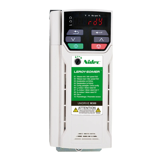
Nidec Commander C200 Step-By-Step Manual
Hide thumbs
Also See for Commander C200:
- Power installation manual (110 pages) ,
- Step-by-step manual (63 pages) ,
- Power installation manual (124 pages)
Subscribe to Our Youtube Channel
Summary of Contents for Nidec Commander C200
- Page 1 Commander C200/C300 Step By Step Guide Guide pas à pas Schritt-für-Schritt-Anleitung Guida dettagliata Guía detallada Frame sizes 1 to 4 Tailles 1 à 4 Baugrößen 1 bis 4 Taglie da 1 a 4 Tamaños 1 a 4...
-
Page 2: Features Of The Drive
English Introduction The Commander C200 and C300 is a simple and flexible range of drives from 0.25 kW to 132 kW in 9 frame sizes and three input voltage ranges (100 V, 200 V, and 400 V). This Step-by Step guide provides simple step-by-step instructions on how to mount the drive, fuse and cable selection, wiring the drive-up, programming the drive and running he motor in analog input mode or keypad mode on frames 1 to 4. -
Page 3: Step 1: Check The Contents Of The Box
STEP 1: Check the contents of the box Check you have all the components and your drive has not been damaged during transportation. SAFETY KIT BAG INFORMATION CABLE BRACKET STEP BY STEP GUIDE STEP 2: Check model and voltage The model number can be found on the identification label on the top of the drive. - Page 4 A Drill template for wall mounting is included on the drive packaging (shown below). Alternativly refer to he table below for the mounting and overall dimensions. Frame Weight Ø Mounting Overall Mounting Overall Overall Diameter 143 mm 160 mm 53 mm 75 mm 130 mm 5 mm...
- Page 5 STEP 4: Select supply / motor cables and fuses or MCB The supply/motor cables and fuses or MCB’s used should follow he ratings provided in the table below: The voltage rating of fuses and MCBs must be greater than or equal to the highest supply voltage of the system.
-
Page 6: Step 5: Remove The Terminal Cover
STEP 5: Remove the terminal cover Using a flat bladed screwdriver, turn the terminal cover locking clip anti-clockwise by approximately 30°. Slide the terminal cover down. Remove terminal cover in direction shown. STEP 6: Wire the drive up Power connections When wiring the drive the power, ground and control connections, they should be ightened to the recommended torque settings shown in the table below: Table 6-1 Recommended torque settings... -
Page 7: Ground Connections
Ground connections The supply and motor ground connections are made using the ground busbar located at the bottom of the drive as shown in Figure 6-2. Electrochemical corrosion of grounding terminals Ensure hat grounding terminals are protected against corrosion i.e. as could be caused by condensation. -
Page 8: Control Connections
Control connections The control terminals are configured by default for he arrangement shown below: Figure 6-3 Commander C200/C300 control terminal connections Digital I/O Analog I/O 24 V user Analog input 1 Digital I/O1 Frequency Zero frequency 10 kW reference 1... -
Page 9: Step 7: Use The Keypad
STEP 7: Use the keypad The display provides information to he user regarding the operating status of the drive, alarms and trip code. The keypad provides the means for changing parameters, stopping and starting the drive, and the ability to perform a drive reset. -
Page 10: Step 8: Run The Motor
STEP 8: Run the motor This step will provide instruction on how to set-up the basic drive parameters, perform an auto-tune and run the motor in analog input terminal mode or keypad mode. Action Detail Power Up Ensure: • The drive displays: inh (Enable terminal(s) is open) Minimum and Enter: maximum speed... -
Page 11: Additional Information Troubleshooting
Additional Information Troubleshooting When the drive detects a fault it will display an error code. To locate and solve all error codes, a ‘Diagnostic Tool (App)’ is available on Microsoft, Android and iOS platform via the ‘Apps’ store on Smartphone / Tablet, search for ‘Control Techniques diagnostics tool in the Apps store’. -
Page 12: Appendix A Ul Listing Information
Appendix A UL listing information This addendum provides additional information requested by UL to be supplied with the product. UL file reference All models are UL Listed to both Canadian and US requirements. The UL file reference is: NMMS/7.E171230. Products that incorporate the Safe Torque Off function have been investigated by UL. The UL file reference is: FSPC.E171230. -
Page 13: Motor Overload Protection And Thermal Memory Retention
National Electrical Code (NEC), The Canadian Electrical Code, and any additional local codes. DYNAMIC BRAKING Commander C200/C300, frame sizes 1 to 4 have been evaluated for dynamic braking applications. Other drive models have not been evaluated for dynamic braking. Motor overload protection and thermal memory retention The devices incorporate solid state overload protection for the motor load.


Need help?
Do you have a question about the Commander C200 and is the answer not in the manual?
Questions and answers