Table of Contents
Advertisement
Quick Links
Advertisement
Table of Contents

Related Manuals for HP pocurve switch 408


Summary of Contents for HP pocurve switch 408
- Page 1 408 www.hp.com/go/ procurve...
- Page 3 HP ProCurve Switch 408 Installation Guide...
- Page 4 Warranty A copy of the specific warranty terms applicable to your Hewlett-Packard prod- ucts and replacement parts can be obtained from your HP Sales and Service Office or authorized dealer. Safety Before installing and operating this product, please read the “Installation Precautions”...
-
Page 5: Table Of Contents
Contents 1 Introducing the Switch 408 Front of the Switch ....... . . 1-2 Network Ports . - Page 6 Testing End-to-End Network Communications ..3-6 HP Customer Support Services ..... 3-6 A Specifications Physical .
-
Page 7: Introducing The Switch 408
Introducing the Switch 408 The HP ProCurve Switch 408 is a multiport switch that can be used to build high-performance switched workgroup networks. This switch is a store-and-forward device that offers low latency for high- speed networking. HP ProCurve Switch 408 (HP J4097B) Throughout this manual, the name of this switch will be abbreviated as the Switch 408. -
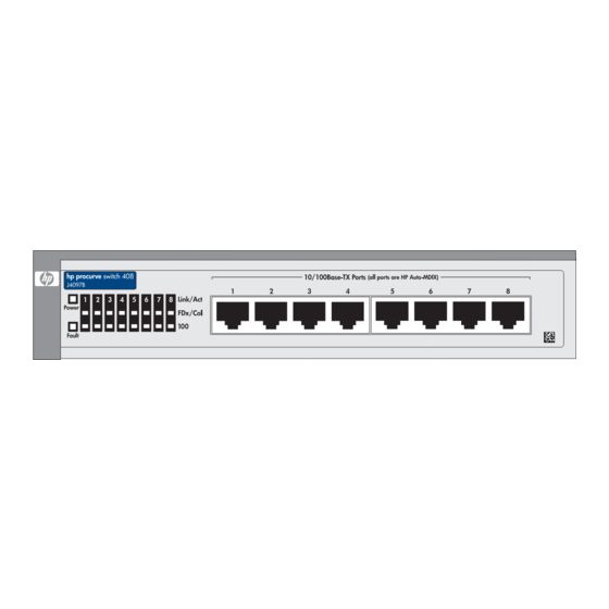
Page 8: Front Of The Switch
Network Ports The switch has 8 auto-sensing 10/100Base-TX ports with RJ-45 connectors. All of the ports have the HP Auto- MDIX feature, which means that either a straight-through or cross-over cable can be used for any connection to another device, and the switch automatically... -
Page 9: Leds
Introducing the Switch 408 Front of the Switch LEDs Table 1-1. Switch LEDs Switch LEDs State Meaning The switch is receiving power. (green) The switch is NOT receiving power. Fault The normal state; indicates that there are no fault (orange) conditions on the switch. -
Page 10: Back Of The Switch
AC power adapter is plugged in to an active power source and to the switch. Caution Use only the AC power adapter supplied with the switch. Use of other adapters, including adapters that came with other HP network products, may result in damage to the equipment. -
Page 11: Features
10 Mbps or 100 Mbps, and automatically operate at that speed HP Auto-MDIX on all ports—all ports allow you to use either a straight-through or crossover cable to connect to any other RJ-45 network device. There are no switches or buttons to deal with, and no more worrying about what type of cable is needed to connect to an end node, or to another switch or hub. - Page 12 Introducing the Switch 408 Switch Operation Overview matically and stored in the Switch 408’s 1000-entry address table. The switch also identifies the number of the port on which each address is learned so it knows the relative network location of each device. Forwarding, Filtering, Flooding.
-
Page 13: Installing The Switch 408
Installing the Switch 408 The HP ProCurve Switch 408 is easy to install. It comes with four rubber feet that can be attached so the switch can be securely located on any level surface (for example, a table or shelf). A mounting kit... -
Page 14: Installation Procedures
Installing the Switch 408 Installation Procedures Installation Procedures Summary Follow these easy steps to install your switch. The rest of this chapter provides details on these steps. Prepare the installation site. Make sure of the following: • the network cabling is the correct type and length. See page 2-5. -
Page 15: Installation Precautions
Installing the Switch 408 Installation Procedures Installation Precautions: Follow these precautions when installing your Switch 408. Cautions Make sure that you use the power adapter supplied with the switch to connect it to an AC power source. When installing the switch, since the unit does not have an On/Off power switch, an AC power outlet must be located near the switch and should be easily accessible in case the switch needs to be powered off. - Page 16 Installing the Switch 408 Installation Procedures Connect no devices that have a fixed full-duplex configuration. Because the switch 408 complies with the IEEE 802.3u standard, if a device connected to the switch has a fixed configuration of full duplex, the device will not connect correctly to the switch.
-
Page 17: Prepare The Installation Site
Cabling Infrastructure - Make sure that the cabling infrastruc- ture meets the necessary network specifications. Because of the HP Auto-MDIX feature, for connections to end nodes (computers, servers, printers and other peripherals), or connec- tions to hubs or other switches, you can use “straight-through”... -
Page 18: Verify The Switch Passes Its Self Test
Use only the AC power adapter supplied with the switch. Use of other adapters, including those that came with other HP network products, may result in damage to the equipment. Check the LEDs on the switch. The LED behavior is described on... - Page 19 Installing the Switch 408 Installation Procedures Switch port LEDs Power and Fault LEDs When the switch is powered on, it performs its diagnostic self test. The self test takes approximately 3 seconds to complete. LED Behavior: During the self test: •...
-
Page 20: Mount The Switch
Installing the Switch 408 Installation Procedures 3. Mount the Switch After you have verified that the switch passes its self test, you are ready to mount the switch in a stable location. The Switch 408 can be mounted in these ways: on a horizontal surface in a rack or cabinet, or on a wall (requires optional bracket kit) Horizontal Surface Mounting... -
Page 21: Connect The Switch To A Power Source
Installing the Switch 408 Installation Procedures 4. Connect the Switch to a Power Source Plug the included AC power adapter into the switch’s power connector and into a nearby AC power source. Re-check the LEDs during self test. See “LED Behavior” on page 2-7. -
Page 22: Sample Network Topologies
Installing the Switch 408 Sample Network Topologies Sample Network Topologies This section shows you two sample network topologies in which the Switch 408 is implemented. Note Make sure the network into which you are installing the Switch 408 has a valid topology: there should be no loops in the data paths connected to the switch, and all twisted- pair connections should be no more than 100 meters. -
Page 23: As A Segment Switch
Installing the Switch 408 Sample Network Topologies As a Segment Switch 100 Mbps connection through category 5 twisted-pair cable Server 100Base-TX connection to a backbone switch Switch 408 Ethernet Hubs twisted-pair cables PCs, printers, twisted-pair and local cables servers In general, the Switch 408 is designed to be used as a desktop switch, but it can also be used as a segment switch. - Page 24 Installing the Switch 408 Sample Network Topologies Note that because of the HP Auto-MDIX feature, all twisted-pair connections between the switch and the MDI-X ports or MDI ports on hubs, and the connections to the end nodes and the servers can be through “straight-through”...
-
Page 25: Troubleshooting
(page 3-1) diagnosing with the LEDs (page 3-3) hardware diagnostic tests (page 3-5) HP Customer Support Services (page 3-6) Basic Troubleshooting Tips Most problems are caused by the following situations: Connecting to devices with a fixed full-duplex configura- tion. - Page 26 Refer to the Network Design Guide for topology configuration guidelines. This guide can be found online at the HP World Wide Web site for networking products, http:// www.hp.com/go/hpprocurve. You can find it quickly by searching for “Network Design Guide”.
-
Page 27: Diagnosing With The Leds
Troubleshooting Diagnosing With the LEDs In addition, you should make sure that your network topology contains no data path loops. Between any two end nodes, there should be only one active cabling path at any time. Data path loops will cause broadcast storms that will severely impact your network performance. - Page 28 If this condition persists, the switch’s power adapter may have failed. Call your HP-authorized LAN dealer, or use the electronic support services from HP to get assistance. See the Customer Support/Warranty booklet for more information. —...
-
Page 29: Hardware Diagnostic Tests
To verify that your cable is compatible with these standards, use a qualified cable test device. HP also offers a wire testing service. Contact your HP-authorized LAN dealer or your local HP sales office for more information. -
Page 30: Testing End-To-End Network Communications
See the Customer Support/Warranty booklet that came with your switch for information on how to use these services to get technical support. The HP networking products World Wide Web site, http://www.hp.com/go/hpprocurve also provides up-to-date support information. -
Page 31: Physical
Specifications Physical Width: 19.9 cm (7.8 in) Depth: 12.1 cm (4.8 in) Height: 4.0 cm (1.6 in) Weight : 0.72 kg (1.60 lbs) Electrical DC voltage: 13 volts Maximum current: 0.8 A Environmental Operating Non-Operating Temperature: 0°C to 55°C (32°F to 131°F) -40°C to 70°C (-40°F to 158°F) Relative humidity: 10% to 90% at 40°C (104°F) -
Page 32: Connectors
The 10/100 Mbps RJ-45 twisted-pair ports are compatible with the IEEE 802.3u 100Base-TX and IEEE 802.3 Type 10Base-T stan- dards. All ports include the HP Auto-MDIX feature, which allows the use of either “straight-through” or “crossover” cables for any twisted-pair connection. -
Page 33: B Cables And Connectors
Pin-Outs The RJ-45 ports (10 Mbps and 100 Mbps) on the Switch 408 have the HP Auto-MDIX feature, which allows you to use either “straight- through” or “crossover” twisted-pair cables for connections to any other network device that has RJ-45 connectors. -
Page 34: Straight-Through Twisted-Pair Cable
Cables and Connectors Twisted-Pair Cable/Connector Pin-Outs For 10 Mbps connections to the ports, you can use 100-ohm Category 3, 4, or 5 unshielded (UTP) or shielded (STP) twisted- pair cable, as supported by the IEEE 802.3 Type 10Base-T stan- dard. For 100 Mbps connections to the ports, use 100-ohm Category 5 UTP or STP cable only, as supported by the IEEE 802.3u Type 100Base-TX standard. -
Page 35: Crossover Twisted-Pair Cable
Cables and Connectors Twisted-Pair Cable/Connector Pin-Outs Crossover Twisted-Pair Cable Connector “A” Connector “B” Crossover Cable white/orange orange/white white/green green/white Note Pins 1 and 2 on connector “A” must be wired as a twisted pair to pins 3 and 6 on connector “B”. Pins 3 and 6 on connector “A”... -
Page 36: Twisted-Pair Cable Pin Assignments
Cables and Connectors Twisted-Pair Cable/Connector Pin-Outs Twisted-Pair Cable Pin Assignments Twisted-Pair Straight-Through Cable Switch End Computer, Transceiver, or Other MDI Port End Signal Pins Pins Signal receive + transmit + receive - transmit - transmit + receive + transmit - receive - Twisted-Pair Crossover Cable Switch End... -
Page 37: C Safety And Emc Regulatory Statements
Safety and EMC Regulatory Statements Safety Information Documentation reference symbol. If the product is marked with this symbol, refer to the product documentation to get more information about the product. WARNING A WARNING in the manual denotes a hazard that can cause injury or death. - Page 38 Safety and EMC Regulatory Statements Safety Information LAN cables may occasionally be subject to hazardous tran- sient voltages (such as lightning or disturbances in the electrical utilities power grid). Handle exposed metal com- ponents of the network with caution. Servicing There are no user-serviceable parts inside these products.
- Page 39 Safety and EMC Regulatory Statements Informations concernant la sécurité Informations concernant la sécurité Symbole de référence à la documentation. Si le produit est marqué de ce symbole, reportez-vous à la documentation du produit afin d'obtenir des informations plus détaillées. WARNING Dans la documentation, un WARNING indique un danger susceptible d'entraîner des dommages corporels ou la mort.
- Page 40 Safety and EMC Regulatory Statements Hinweise zur Sicherheit Hinweise zur Sicherheit Symbol für Dokumentationsverweis. Wenn das Produkt mit diesem Symbol markiert ist, schlagen Sie bitte in der Produkt- dokumentation nach, um mehr Informationen über das Produkt zu erhalten. WARNING Eine WARNING in der Dokumentation symbolisiert eine Gefahr, die Verletzungen oder sogar Todesfälle verursachen kann.
- Page 41 Safety and EMC Regulatory Statements Considerazioni sulla sicurezza Considerazioni sulla sicurezza Simbolo di riferimento alla documentazione. Se il prodotto è contrassegnato da questo simbolo, fare riferimento alla docu- mentazione sul prodotto per ulteriori informazioni su di esso. WARNING La dicitura WARNINGdenota un pericolo che può causare lesioni o morte.
- Page 42 Safety and EMC Regulatory Statements Consideraciones sobre seguridad Consideraciones sobre seguridad Símbolo de referencia a la documentación. Si el producto va marcado con este símbolo, consultar la documentación del producto a fin de obtener mayor información sobre el producto. WARNING Una WARNING en la documentación señala un riesgo que podría resultar en lesiones o la muerte.
-
Page 43: Safety Information
Safety and EMC Regulatory Statements Safety Information (Japan) Safety Information (Japan) - Page 44 Safety and EMC Regulatory Statements Safety Information (China) Safety Information (China)
-
Page 45: Emc Regulatory Statements
Safety and EMC Regulatory Statements EMC Regulatory Statements EMC Regulatory Statements U.S.A. FCC Class A This equipment has been tested and found to comply with the limits for a Class A digital device, pursuant to Part 15 of the FCC Rules. These limits are designed to provide reasonable protection against interference when the equipment is operated in a commercial envi- ronment. - Page 46 Safety and EMC Regulatory Statements EMC Regulatory Statements Japan VCCI Class A Korea Taiwan C-10...
- Page 47 8000 Foothills Blvd. Manufacturer's Address: Roseville, CA 95747-5502 U.S.A. declares that the product: Product Names: HP ProCurve Switch 408 Model Numbers: J4097B Accessories: Conform to the following Product Specifications: Safety: EN60950:1992 +A1, A2, A3, A4, A11 / IEC 60950:1991 +A1, A2, A3, A4...
- Page 49 … 1-6 moves and changes connecting the switch to a power … 1-5 operation … 2-9 source Auto-MDIX … A-2 connector specifications see HP Auto-MDIX crossover cable … B-4 pin-out back of switch … 1-4 description description … 1-4 power connector …...
- Page 50 … 2-5 100Base-TX connections horizontal surface, mounting switch … 2-5 10Base-T connections … 2-8 … 1-3 Link/Act LEDs HP Auto-MDIX … 2-5, 2-12, affect on cable usage A-2–B-1 … 1-5 description Index – 2...
- Page 51 … 1-4 power connector … 1-3 Power LED mounting the switch … 2-7 behavior during self test … 2-8 in a rack or cabinet power source … 2-8 on a horizontal surface … 2-9 connecting the switch to … 2-8 on a wall precautions moves and changes...
- Page 52 switch troubleshooting … 3-1 connecting to a power basic tips … 2-9 … 3-5 source checking the LEDs … A-1 … 3-1 electrical specifications common network problems … 3-5 environmental diagnostic tests … A-1 … 3-2 specifications effects of improper topology …...
- Page 54 Technical information in this document is subject to change without notice. ©Copyright Hewlett-Packard Company 2001. All rights reserved. Reproduction, adaptation, or translation without prior written permission is prohibited except as allowed under the copyright laws. Printed in Taiwan 3/01 Manual Part Number J4097-90101 *J4097-90101*...
Need help?
Do you have a question about the pocurve switch 408 and is the answer not in the manual?
Questions and answers