
Subscribe to Our Youtube Channel
Related Manuals for HP ProCurve Series


Summary of Contents for HP ProCurve Series
- Page 1 ProCurve Series 3500yl and 6200yl Switches Power over Ethernet Devices www.procurve.com Installation and Getting Started Guide...
- Page 3 ProCurve Series 3500yl and 6200yl Switches Installation and Getting Started Guide...
- Page 4 The only warranties for HP products and services are set forth in the express warranty statements accompanying such products and services. Nothing herein should be construed as constituting an additional warranty.
-
Page 5: Table Of Contents
6. Mount the Switch ........ - Page 6 Stacking the Switch ........
- Page 7 Downloading New Switch Software ......5-12 HP Customer Support Services ........5-12 Before Calling Support .
- Page 8 Straight-Through Twisted-Pair Cable for 10 Mbps or 100 Mbps Network Connections ....B-6 Crossover Twisted-Pair Cable for 10 Mbps or 100 Mbps Network Connection ..... B-7 Straight-Through Twisted-Pair Cable for 1000 Mbps Network Connections .
-
Page 9: Introducing The Switch
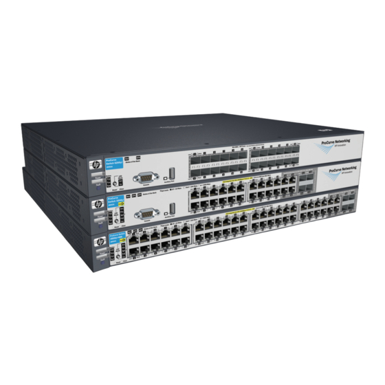
ProCurve Switch 3500yl-24G-PWR (J8692A) ProCurve Switch 3500yl-48G-PWR (J8693A) ProCurve Switch 6200yl-24G mGBIC (J8992A) Throughout this manual, this switch will be abbreviated as the Switch 3500yl- 24G, Switch 3500yl-48G or Switch 6200yl-24G. The Switch 3500yl-24G and Switch 3500yl-48G have respectively, 24 or 48, auto-sensing 10/100/1000Base-TX RJ-45 ports, four dual-personality ports—... - Page 10 PoE devices. For a list of these devices, see the FAQs for your switch model. This feature is the default and you must disable it if you do not want to use it. (Refer to the Management and Configuration Guide which is on the ProCurve Web site, www.procurve.com.
-
Page 11: Front Of The Switch
Reset and Clear buttons Port LED Mode select button and indicator LEDs *On the 3500yl-48G switch, the Console and Auxiliary ports are located on the back of the unit. Figure 1-1. Front of the ProCurve Switch 3500yl-24G. PoE, Temp, Fan, and Power,... -
Page 12: Network Ports
Figure 1-3. Front of the ProCurve Switch 6200yl-24G. Network Ports ■ 24 or 48 auto-sensing 10/100/1000Base-T ports. All these ports have the “HP Auto MDIX” feature, which means you can use either straight-through or crossover twisted-pair cables to connect any network devices to the switch. ■... -
Page 13: Leds
The normal state; indicates there are no fault conditions on the switch. (orange) blink A fault has occurred on the switch, one of the switch ports, module in the rear of the orange* switch, or the fan. The Status LED for the component with the fault will blink simultaneously. - Page 14 The switch is not connected to an EPS. Fan Status Normal operation, all fans are ok. (green/ Blink One of the unit’s fans has failed. The switch Fault LED will be blinking simultaneously. orange) orange* PoE Status When the switch is ready to start supplying PoE power.
-
Page 15: Led Mode Select Button And Indicator Leds
Press the button to step from one view mode to the next. Expansion Module LED LED Mode select button and indicator LEDs Figure 1-4. Indicator LEDs on the ProCurve Switch 3500yl-24G. Expansion Module LEDs LED Mode select button and indicator LEDs Figure 1-5. -
Page 16: Reset Button
Off = PoE is not being supplied on this port. Reset Button This button is used to reset the switch while it is powered on. This action clears any temporary error conditions that may have occurred and executes the switch self test. It is also used when restoring the switch factory default configuration. -
Page 17: Clear Button
“Expansion Module” LEDs refer to the LEDs specific to the expansion module. These LEDs are located on the physical expansion module bulkhead. These LEDs are only viewable in the rear of the Switch 3500yl-48G product on the Expansion Slot Module itself. These LEDs are duplicated on the front panel of the Switch 3500yl-24G and 6200yl-24G devices. - Page 18 Expansion module LEDs operate in modes for Link and Activity. FDx and Spd modes have no meaning for the 10-GbE ports on the expansion module. C a u t i o n It is required the switch be powered down before inserting or extracting the Expansion Module. 1-10...
-
Page 19: Back Of The Switch
Back of the Switch yl module slot Figure 1-7. Back of the ProCurve Switch 3500yl-24G. yl module slot Console Port Figure 1-8. Back of the ProCurve Switch 3500yl-48G. yl module slot Figure 1-9. Back of the ProCurve Switch 6200yl-24G. EPS Input Port... -
Page 20: Yl Module Slot
PoE power to the switch products to back up the power supply in the switch in case of loss of AC or PoE power. Or If maximum PoE power is being used on all 48 ports, a 620 RPS/EPS will be necessary to provide full power to the second 24 ports, and in this case, there would be no redundancy. -
Page 21: Switch Features
Switch Features The features of the Series 3500yl and 6200yl Switches include: ■ 24 or 48 auto-sensing 10/100/1000Base-T RJ-45 ports with HP Auto-MDIX. ■ Four dual-personality ports—either the auto sensing 10/100/1000Base-T RJ-45 or the mini-GBIC can be used for each port. - Page 22 Management and Configuration Guide, which is on the ProCurve Web site at www.procurve.com. See details. ■ Download of new switch software for product enhancements or bug fixes. ■ Support for IEEE 802.3af Standard and Pre-standard PoE devices. 1-14...
-
Page 23: Installing The Switch
C a u t i o n If the switch is to be shipped in a rack, be sure to use only an HP 10K rack. Mount the switch using rail kit, ProCurve 1U RK MT SWITCH 10K ALL, part number 356578-B21 and shelf kit AB469A, HP rx 16/26 Factory Rackmount Shelf Kit. - Page 24 3500yl and 6200yl Switches two mounting brackets eight 8-mm M4 screws to attach the mounting brackets to the switch four 5/8-inch number 12-24 screws to attach the switch to a rack four rubber feet ■ Power cord, one of the following: Australia/New Zealand...
-
Page 25: Installation Procedures
PC to the switch’s console port. At this point, the switch is fully installed. See the rest of this chapter if you need more detailed information on any of these installation steps. -
Page 26: Installation Precautions
C a u t i o n s If the switch is to be shipped in a rack, be sure to use only an HP 10K rack. ■ Mount the switch using rail kit part number 356578-B21 and shelf kit AB469A. -
Page 27: Prepare The Installation Site
Fiber ribbon cable. 12 fiber 62.5/125 μm (core/cladding) diameter, multimode Fiber Converter) ribbon cable is also supported. “Switch Ports and Network Cables” Summary of Cable Types to Use With the Switch Length Limits Twisted-Pair Cables 100 meters Note: The Series 3500yl and 6200yl Switches are compatible with the IEEE 802.3ab standard... - Page 28 Installing the Switch Installation Procedures Port Type Cable Type Gigabit-SX Multimode fiber-optic cables designed for Gigabit Ethernet: 62.5/125 μm or 50/125 μm (on Gigabit-SX-LC mini-GBIC) (core/cladding) diameter, 850 nm, low metal content, graded-index cables, fitted with LC connectors. The cables must comply with the ITU-T G.651 and ISO/IEC 793-2 Type A1b or A1a...
-
Page 29: Optional) Install Or Remove A Yl Module
Installation Location - Before installing the switch, plan its location and orientation relative to other devices and equipment: • In the front of the switch, leave at least 7.6 cm (3 inches) of space for the twisted-pair and fiber-optic cabling. •... -
Page 30: Optional) Install Or Remove A Transceiver
Figure 2-3. Securing a transceiver bail. N o t e When switch power is on, the Link and Activity LEDs will come on for approximately two seconds and then go off. This is confirmation the trans- ceiver is completely seated. -
Page 31: Optional) Install Or Remove Mini-Gbics
ProCurve Gigabit-LH-LC mini-GBIC (J4860B) C a u t i o n Use only supported genuine ProCurve mini-GBICs with your switch. Non- ProCurve mini-GBICs are not supported, and their use may result in product malfunction. Should you require additional ProCurve mini-GBICs, contact your ProCurve Networking Sales and Service Office or authorized dealer. - Page 32 (you can see it move outward slightly), and then pull it from the slot. To remove the mini-GBICs that have the wire bail, lower the bail until it is approximately horizontal, and then using the bail, pull the mini-GBIC from the slot.
-
Page 33: Verify The Switch Passes Self Test
The Series 3500yl and 6200yl Switches do not have a power switch. They are powered on when the power cord is connected to the switch and to a power source. For safety, the power outlet should be located near the switch installation. - Page 34 Power and Test LED Fault LEDs Figure 2-6. LEDs on the yl switches. When the switch is powered on, it performs its diagnostic self test. Self test takes approximately 50 seconds to complete. 2-12 ProCurve Switch 3500yl-24G Switch port LEDs...
-
Page 35: Led Behavior
Refer to chapter 4, “Troubleshooting” for diagnostic help. 6. Mount the Switch After the switch passes self test, you are ready to mount the switch in a stable location. The Series 3500yl and 6200yl Switches can be mounted in these ways: ■... -
Page 36: Rack Mounting The Switch 3500Yl-24G
The mounting brackets have multiple mounting holes and can be rotated allowing for a wide variety of mounting options. These include mounting the switch so its front face is flush with the face of the rack, or mounting it in a more balanced position as shown in the illustration. -
Page 37: Horizontal Surface Mounting
Horizontal Surface Mounting Place the switch on a table or other horizontal surface. The switch comes with rubber feet in the accessory kit that can be used to help keep the switch from sliding on the surface. Attach the rubber feet to the four corners on the bottom of the switch within the embossed angled lines. -
Page 38: Connect The Network Cables
See the table on mini-GBIC cabling information. For mini-GBICs ports, and in general for all the switch ports, when a network cable from an active network device is connected to the port, the port LED for that port should go on. If the port LED does not go on when the network cable is connected to the port, see in chapter 5, “Troubleshooting”. -
Page 39: Connecting A Fiber Cable
If the port LED does not go on when the network cable is connected to the port, see chapter 5, “Troubleshooting”. Installing the Switch Installation Procedures Figure 2-10. Connecting fiber optic cable. 5-4, in chapter 5, “Troubleshooting”. -
Page 40: Optional) Connect A 620 Redundant Power Supply
■ External Power-over-Ethernet (PoE) power to up to two switch products. The 620 RPS/EPS can supply 398 watts of PoE power to the switch if the internal PoE power supply should fail. For the Switch 3500yl-48G-PWR the external PoE power is additional power made available to the switch’s ports. -
Page 41: Operating Characteristics Of The 620 Rps/Eps (J8696A)
The 620 RPS/EPS has two RPS ports, each of which can provide redundant +12V power to a connected switch. If a switch with no AC power is connected to an operating 620 RPS/EPS, it will not receive power. The switch must first be powered on, then connected to the 620 RPS/EPS. - Page 42 • When the LED is blinking simultaneously with the Fault LED, there is a fault The blinking behavior is an on/off cycle once every 1.6 seconds, approximately. The blinking behavior is an on/off cycle once every 0.8 seconds, approximately. Specific fault conditions can be viewed by checking switch log files. 2-20 simultaneously.
-
Page 43: 620 Rps/Eps Connectivity
This section shows some recommended connection topologies using the 620 RPS/EPS. The 620 RPS/EPS can provide backup power support for up to two ProCurve switches. In the illustration below, two ProCurve Switch 3500yl- 24G-PWR units are connected to the RPS ports on a 620 RPS/EPS. -
Page 44: 10. (Optional) Connect A Console To The Switch
“Function, Arrow, and Ctrl Keys act as” parameter If you want to operate the console using a different configuration, make sure you change the settings on both the terminal and on the switch so they are compatible. Change the switch settings first, save your changes, then change the terminal settings, then reboot the switch and reestablish the console session. -
Page 45: Direct Console Access
Press a key, and you will then see the switch console command (CLI) prompt, for example: ProCurve Switch 3500yl-24G# If you want to continue with console management of the switch at this time, see chapter 3, “Getting Started With Switch Configuration”... -
Page 46: Sample Network Topologies
Fast Ethernet cable Figure 2-16. As a Desktop Switch. The Switch is designed to be used primarily as a desktop switch to which end nodes, printers and other peripherals, and servers are directly connected, as shown in the above illustration. Notice that the end node devices are connected to the switch by straight-through or crossover twisted-pair cables. - Page 47 As shown in the above illustration the IP telephones can be connected in line, that is, between the switch and the end device, in this case a PC. The IP telephones in this illustration have two ports, one in and one out. Therefore the phone receives voice and power from the switch and the PC can send and receive data through the phone to the switch.
- Page 48 Fiber cable Figure 2-18. As a Segment Switch. The Switch also works well as a segment switch. That is, with its high performance, it can be used for interconnecting network segments—simply connect the network hubs that form those segments to the switch, or you can also connect other switches.
- Page 49 Because the Switch has the “IEEE Auto MDI/MDI-X” features, the connections between the switch and the hubs, and between the switch and end nodes or servers can be through category 5 straight-through or crossover twisted-pair cable. Category 3 or 4 cable can also be used if the connection is 10 Mbps only.
- Page 50 All the devices in this network can communicate with each other. With a Gigabit-SX Module, for example, in the Switch 5304xl, the entire switched topology could be connected to a campus backbone, as shown in figure 2-3.
-
Page 51: Stacking The Switch
N o t e In the Backbone Switch illustration, the 1000 Mbps fiber-optic connection between the Switch 3500yl-24G and the Switch 5304xl is by way of a Gigabit- SX mini-GBIC installed in the Switch 3500yl-24G and connected to a Gigabit- SX Module in the Switch 5304xl. - Page 52 Installing the Switch Sample Network Topologies Stack of two 3500yl-24G Serial No. SG12345678 System MAC Address 00 -01-E7 -12-34 -56 switches using CX4 Mdl S tatus Link cables trunked. Activity Serial No. SG12345678 System MAC Address 00 -01-E7 -12-34 -56...
-
Page 53: Optimizing The 10-Gbe Port Configuration
Figure 2-24. Stacking three switches using CX4 and fiber. Optimizing the 10-GbE Port Configuration The 10-GbE ports on the ProCurve Switch 3500yl and 6200yl series are designed to deliver full 10 Gbps wire-speed to each port, where either one or two ports are in a linked state with another device. - Page 54 Installing the Switch Sample Network Topologies When any two 10-GbE ports are in a linked state, each port automatically operates on its own channel, which guarantees 10 Gbps of bandwidth for each port. However, when more than two ports are in a linked state, ports A1 and A4 are statically mapped to share one 14.4 Gbps channel, while ports A2 and...
-
Page 55: Getting Started With Switch Configuration
Getting Started With Switch Configuration This chapter is a guide for using the console Switch Setup screen to quickly assign an IP (Internet Protocol) address and subnet mask to the switch, set a Manager password, and, optionally, configure other basic features. -
Page 56: Using The Console Setup Screen
The quickest and easiest way to minimally configure the switch for manage- ment and password protection in your network is to use a direct console connection to the switch, start a console session, and access the Switch Setup screen. Using the method described in the preceding section, connect a terminal device to the switch and display the switch console command (CLI) prompt (the default display). - Page 57 Recommended; If you set IP Config to Manual, then enter an IP address Note: The IP address and subnet mask assigned for the switch must be compatible with the IP addressing used in your network. For more information on IP addressing, see the Management and Configuration Guide, which is on the ProCurve Web site at www.procurve.com.
-
Page 58: Where To Go From Here
The above procedure configures your switch with a Manager password, IP address, and subnet mask. As a result, with the proper network connections, you can now manage the switch from a PC equipped with Telnet, a web browser interface, or from an SNMP-based network management station using a tool such as ProCurve Manager. -
Page 59: Using The Ip Address For Remote Switch Management
With your yl switch, you can use the switch’s IP address to manage the switch from any PC that is on the same subnet as the switch. You can use either a Telnet session or a standard web browser to manage the switch. - Page 60 (See An extensive help system is also available for the web browser interface. To access the help system though, the subnet on which the switch is installed must have access to the internet, or ProCurve Manager needs to be installed on a network management station that is on the subnet.
-
Page 61: Replacing Components
The fan tray is not hot swappable. Replacing the fan try must be done during scheduled downtime. When a fan fails the Fan Status LED on the switch will blink simultaneously with the switch Fault LED. In this case, the entire fan tray needs to be replaced. - Page 62 Figure 4-1. Fan tray retaining screw and cable. Install the new fan tray assembly, reconnect the fan tray cable connector, reinstall and tighten the retaining screw. Reinstall the top of the switch. Align the top cover pin with the hole. Top Cover Pin Alignment Hole Figure 4-2.
-
Page 63: Replacing The Battery
Replacing the Battery The battery is used to keep time for the internal switch clock. There is not LED indicator for when the battery no longer has sufficient power. The only indication will be the internal clock will not keep the correct time. The battery is not hot swappable. - Page 64 Insert a new battery with the lettering and the plus “+” sign facing up. Be sure to replace with the same type of battery. Reinstall the top of the switch. Ensure you correctly align the top cover pin. Top Cover Pin...
-
Page 65: Troubleshooting
This chapter describes how to troubleshoot your switch. This document describes troubleshooting mostly from a hardware perspective. You can perform more in-depth troubleshooting on the switch using the software tools available with the switch, including the full-featured console interface, the built-in web browser interface, and ProCurve Manager, the SNMP-based network management tool. -
Page 66: Basic Troubleshooting Tips
Connecting to devices that have a fixed full-duplex configuration. ■ The RJ-45 ports are configured as “Auto”. That is, when connecting to attached devices, the switch will operate in one of two ways to determine the link speed and the communication mode (half duplex or full duplex): •... - Page 67 Data path loops will cause broadcast storms that will severely impact your network performance. For your switch, if you wish to build redundant paths between important nodes in your network to provide some fault tolerance, you should enable Spanning Tree Protocol support on the switch.
-
Page 68: Diagnosing With The Leds
* This LED is not important for the diagnosis. † The blinking behavior is an on/off cycle once every 1.6 seconds, approximately. ** The Module Status LED is located on the module in the rear of the switch. F - Front B - Back... -
Page 69: Diagnostic Tips
Try power cycling the switch. If the fault indication reoccurs, the switch may have failed. hardware failure Call your ProCurve authorized LAN dealer, or use the electronic support services from HP has occurred. All to get assistance. See the Customer Support/Warranty booklet for more information. - Page 70 – For twisted-pair connections to the fixed 10/100 or 10/100/1000 ports, if the port is configured to “Auto” (auto negotiate), either straight-through or crossover cables can be used because of the switch’s “HP Auto-MDIX” feature and the Auto MDI/ MDI-X feature of the 10/100/1000-T port.
- Page 71 Use the switch console to see if the port is part of a dynamic trunk (through the LACP improperly feature) or to see if Spanning Tree is enabled on the switch, and to see if the port may configured, or have been put into a “blocking”...
-
Page 72: Proactive Networking
Troubleshooting Proactive Networking Proactive Networking The ProCurve Series 3500yl and 6200yl Switches have built-in management capabilities that proactively help you manage your network including: ■ finding and helping you fix the most common network error conditions (for example, faulty network cabling, and non-standard network topolo-... -
Page 73: Hardware Diagnostic Tests
Checking the Switch LEDs The self test passes if the Fault and Self Test LEDs on the front of the switch go off after approximately 50 seconds. If these LEDs stay on longer than 60 seconds or begin blinking, there may be a problem with the switch. -
Page 74: Testing Twisted-Pair Cabling
LAN adapters between which you can run a link-level test or Ping test through the switch, you can use this test to verify that the entire communication path between the two PCs is functioning correctly. See your LAN adapter documentation for more information on running a link test or Ping test. -
Page 75: Restoring The Factory Default Configuration
(usually disabling them) may result in network connectivity issues. If the switch has a valid configuration, and you are restoring the factory default settings for a reason other than configuration problems, you should save the switch configuration prior to performing the factory default reset. -
Page 76: Downloading New Switch Software
24 hours a day, seven days a week through the use of a number of automated electronic services. See the Customer Support/Warranty booklet that came with your switch for information on how to use these services to get technical support. The ProCurve Web site, support information. -
Page 77: Specifications
Specifications Physical Width: Depth: Height: Weight: Electrical The switch automatically adjusts to any voltage between 100-127 and 200-240 volts and either 50 or 60 Hz. AC voltage: Maximum current: Frequency range: Environmental Temperature: Relative humidity: (non-condensing) Maximum altitude: If you are installing either the Series 3500yl or 6200yl Switches using any of the X2 transceivers, the operating ambient temperature should not exceed 40°C (104°F). -
Page 78: Acoustic
Specifications Acoustic ProCurve Switch 3500yl-24G-PWR (J8692A) and ProCurve Switch 6200yl-24G-mGBIC (J8992A) Geraeuschemission LpA=49.3 dB am fiktiven Arbeitsplatz nach DIN 45635 T.19 Noise Emission LpA=49.3 dB at virtual workspace according to DIN 45635 T.19 ProCurve Switch 3500yl-48G-PWR (J8692A) Geraeuschemission LpA=52 dB am fiktiven Arbeitsplatz nach DIN 45635 T.19... -
Page 79: Lasers
Lasers The following products are Class 1 Laser Products. Laser Klasse 1: The 10-GbE X2-SC SR transceiver ■ ■ The 10-GbE X2-SC LR transceiver The 10-GbE X2-SC ER transceiver ■ The following products are Class 1m Laser Products. Laser Klasse 1m: ■... -
Page 81: B Switch Ports And Network Cables
Switch Ports and Network Cables This appendix includes switch connector information and network cable information for cables that should be used with the Switch 3500, including minimum pin-out information and specifications for twisted-pair cables. N o t e Incorrectly wired cabling is the most common cause of problems for LAN communications. - Page 82 Equal-Level Far-End Crosstalk (ELFEXT) and Return Loss. When testing your cabling, be sure to include the patch cables that connect the switch and other end devices to the patch panels on your site. The patch cables are frequently overlooked when testing cable and they must also comply with the cabling standards.
-
Page 83: Mode Conditioning Patch Cord For Gigabit-Lx
If you experience a high number of transmission errors on the Gigabit-LX ports, usually CRC or FCS errors, you may need to install one of these patch cords between the Gigabit-LX port in your switch and your multimode fiber- optic network cabling, and between the Gigabit-LX transmission device and the network cabling at the other end of the multimode fiber-optic cable run. -
Page 84: Installing The Patch Cord
Switch Ports and Network Cables Mode Conditioning Patch Cord for Gigabit-LX Installing the Patch Cord As shown in the illustration below, connect the patch cord to the Gigabit-LX mini-GBIC with the section of single-mode fiber plugged in to the Tx (transmit) port. -
Page 85: Twisted-Pair Cable/Connector Pin-Outs
-- you no longer have to use crossover cables, although crossover cables can also be used for any of the connections. If you connect a Switch 3500 twisted-pair port to another switch or hub, which typically have MDI-X ports, the Switch 3500 port automatically operates as an MDI port. -
Page 86: Straight-Through Twisted-Pair Cable For 10 Mbps Or 100 Mbps Network Connections
Straight-Through Twisted-Pair Cable for 10 Mbps or 100 Mbps Network Connections Because of the HP Auto-MDIX operation of the 10/100 ports on the switch, for all network connections, to PCs, servers or other end nodes, or to hubs or other switches, you can use straight-through cables. -
Page 87: Crossover Twisted-Pair Cable For 10 Mbps Or 100 Mbps Network Connection
Crossover Twisted-Pair Cable for 10 Mbps or 100 Mbps Network Connection The HP Auto-MDIX operation of the 10/100 ports on the switch also allows you to use crossover cables for all network connections, to PCs, servers or other end nodes, or to hubs or other switches. -
Page 88: Straight-Through Twisted-Pair Cable For 1000 Mbps Network Connections
Switch Ports and Network Cables Twisted-Pair Cable/Connector Pin-Outs Straight-Through Twisted-Pair Cable for 1000 Mbps Network Connections 1000Base-T connections require that all four pairs or wires be connected. Cable Diagram N o t e Pins 1 and 2 on connector “A” must be wired as a twisted pair to pins 1 and 2 on connector “B”. -
Page 89: C Safety And Emc Regulatory Statements
These products do not have a power switch; they are powered on when the power cord is plugged in. Documentation reference symbol. If the product is marked with this symbol, refer to the product documentation to get more information about the product. -
Page 90: Informations Concernant La Sécurité
Safety and EMC Regulatory Statements Informations concernant la sécurité Informations concernant la sécurité WARNING Caution Cet appareil est un produit de classe I et possède une borne de mise à la terre. La source d'alimentation principale doit être munie d'une prise de terre de sécurité installée aux bornes du câblage d'entrée, sur le cordon d'alimentation ou le cordon de raccordement fourni avec le produit. -
Page 91: Hinweise Zur Sicherheit
Hinweise zur Sicherheit Symbol für Dokumentationsverweis. Wenn das Produkt mit diesem Symbol markiert ist, schlagen Sie bitte in der Produktdokumentation nach, um mehr Informationen über das Produkt zu erhalten. WARNING Eine WARNING in der Dokumentation symbolisiert eine Gefahr, die Verletzungen oder sogar Todesfälle verursachen kann. Caution Caution in der Dokumentation symbolisiert eine Gefahr, die dis Gerät beschädigen kann. -
Page 92: Considerazioni Sulla Sicurezza
Safety and EMC Regulatory Statements Considerazioni sulla sicurezza Considerazioni sulla sicurezza WARNING Caution Questo prodotto è omologato nella classe di sicurezza I ed ha un terminale protettivo di collegamento a terra. Dev'essere installato un collegamento a terra di sicurezza, non interrompibile che vada dalla fonte d'alimentazione principale ai terminali d'entrata, al cavo d'alimentazione oppure al set cavo d'alimentazione fornito con il prodotto. -
Page 93: Consideraciones Sobre Seguridad
Consideraciones sobre seguridad Símbolo de referencia a la documentación. Si el producto va marcado con este símbolo, consultar la documentación del producto a fin de obtener mayor información sobre el producto. WARNING Una WARNING en la documentación señala un riesgo que podría resultar en lesiones o la muerte. -
Page 94: Safety Information (Japan
Safety and EMC Regulatory Statements Safety Information (Japan) Safety Information (Japan) J a p a n P o w e r C o r d W a r n i n g... -
Page 95: Safety Information (China
Safety and EMC Regulatory Statements Safety Information (China) Safety Information (China) -
Page 96: U.s.a
Safety and EMC Regulatory Statements EMC Regulatory Statements EMC Regulatory Statements U.S.A. FCC Class A This equipment has been tested and found to comply with the limits for a Class A digital device, pursuant to Part 15 of the FCC Rules. These limits are designed to provide reasonable protection against interference when the equipment is operated in a commercial environment. -
Page 97: Korea
Safety and EMC Regulatory Statements EMC Regulatory Statements Korea Taiwan... -
Page 98: European Community
Safety and EMC Regulatory Statements EMC Regulatory Statements European Community C-10... -
Page 99: D Recycle Statements
Recycle Statements Waste Electrical and Electronic Equipment (WEEE) Statements Disposal of Waste Equipment by Users in Private Household in the European Union This symbol on the product or on its packaging indicates that this product must not be disposed of with your other household waste. - Page 100 Recycle Statements Waste Electrical and Electronic Equipment (WEEE) Statements Laitteiden hävittäminen kotitalouksissa Euroopan unionin alueella Jos tuotteessa tai sen pakkauksessa on tämä merkki, tuotetta ei saa hävittää kotitalousjätteiden mukana. Tällöin hävitettävä laite on toimitettava sähkölaitteiden ja elektronisten laitteiden kierrätyspisteeseen. Hävitettävien laitteiden erillinen käsittely ja kierrätys auttavat säästämään luonnonvaroja ja varmistamaan, että...
- Page 101 Smaltimento delle apparecchiature da parte di privati nel territorio dell'Unione Europea Questo simbolo presente sul prodotto o sulla sua confezione indica che il prodotto non può essere smaltito insieme ai rifiuti domestici. È responsabilità dell'utente smaltire le apparecchiature consegnan- dole presso un punto di raccolta designato al riciclo e allo smaltimento di apparecchiature elettriche ed elettroniche.
- Page 102 Para obter mais informações sobre locais que reciclam esse tipo de material, entre em contato com o escritório da HP em sua cidade, com o serviço de coleta de lixo ou com a loja em que o produto foi adquirido.
- Page 103 AC power connector location on back of switch … 1-11 Act LED … 1-5, 1-8, 1-10 auto MDI/MDI-X operation … B-6, B-8 HP Auto-MDIX feature … B-5 back of switch description … 1-11 power connector … 1-12 RPS input port … 1-12 yl module slot …...
- Page 104 HP Auto-MDIX feature … B-5 wiring rules … B-5 cables, twisted-pair connector pin-outs … B-5 cabling infrastructure … 2-5 Clear button deleting passwords … 1-9 location on switch … 1-3 restoring factory default configuration … 1-9, 5-11 to delete password protection … 3-4 clear button description …...
- Page 105 … 3-1 in-band console access types of … 2-22 included parts … 2-1 installation connecting the switch to a power source … 2-15 horizontal surface mounting … 2-15 location considerations … 2-7 network cable requirements … 2-5 precautions … 2-4 rack or cabinet mounting …...
- Page 106 1000Base-LH connections … 2-6 1000Base-LX connections … 2-6 1000Base-SX connections … 2-6 1000Base-T connections … 2-5 fiber-optic, specifications … B-2 HP Auto-MDIX feature … B-5 required types … 2-5 twisted-pair connector pin-outs … B-5 twisted-pair, wiring rules … B-5 network devices connecting to the switch …...
- Page 107 … B-6, B-8 subnet mask configuring … 3-3 summary of cables used with the switch … 2-5 of switch installation … 2-3 switch connecting to a power source … 2-15 description … 1-1 downloading new software … 5-12 electrical specifications …...
- Page 108 … B-6, B-8 switch-to-switch or hub connection … B-7 testing … 5-10 twisted-pair ports HP Auto-MDIX feature … B-5 Usr LEDs … 1-6 VT-100 terminal serial cable connection for … 2-23 wiring rules for twisted-pair cables … B-5 yl module install or remove …...
- Page 110 © Copyright 2005, 2006, 2008 Hewlett-Packard Development Company, L.P. Printed in Singapore December 2008 Manual Part Number 5991-4738 *5991-4738*...
Need help?
Do you have a question about the ProCurve Series and is the answer not in the manual?
Questions and answers