Table of Contents
Advertisement
Quick Links
Advertisement
Table of Contents
Troubleshooting

Related Manuals for Ruijie RG-S6110 Series


Summary of Contents for Ruijie RG-S6110 Series
- Page 1 RG-S6110 Series Switches Hardware Installation and Reference Guide V1.0...
- Page 2 This document is provided “as is”. The contents of this document are subject to change without any notice. Please obtain the latest information through the Ruijie Networks website. Ruijie Networks endeavors to ensure content accuracy and will not shoulder any responsibility for losses and damages caused due to content omissions, inaccuracies or errors.
- Page 3 It is intended for the users who have some experience in installing and maintaining network hardware. At the same time, it is assumed that the users are already familiar with the related terms and concepts. Obtaining Technical Assistance Ruijie Networks Website: https://www.ruijienetworks.com/ Technical Support Website: https://ruijienetworks.com/support...
-
Page 4: Product Overview
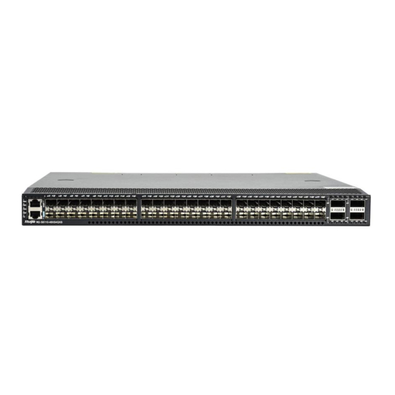
The RG-S6110-48XS4QXS series switches are the high-density 10G layer 3 IPv6 cassette switches introduced by Ruijie Networks. They are mainly applicable to the data center to provide the convergence access for the servers. An SFP+ port supports both 10Gbase-R and 1000base-X. - Page 5 Hardware Installation and Reference Guide Product Overview Working Humidity 10% to 90% RH(non-condensing) Weight Net weight 9KG (including four fan modules and two power modules) Dimensions 440 x 420 x 44 (L x W x H, mm),1RU RG-S6110-48XS4QXS switch is a class A product. In a domestic environment, this product may cause radio interference in which case the user may be required to take adequate measures.
- Page 6 Hardware Installation and Reference Guide Product Overview ① Switch status indicator ⑦ 40G QSFP+ port status indicator Notes: ② PWR1 status indicator ⑧ 10/100/1000Base-T RCMI Ethernet port ③ PWR2 status indicator ⑨ Console ④RCMI management interface ⑩ 10G SFP+ port indicator ⑪...
- Page 7 Hardware Installation and Reference Guide Product Overview To protect the data and avoid device damage, use qualified USB flash disks of good brands. At the same time, the local USB interface is compatible with most of the USB controllers except some USB flash disks. ...
- Page 8 Hardware Installation and Reference Guide Product Overview (4 x 10G Solid green Port 10G is linked up. indicator mode) Blinking green Port 10G is transceiving data. The port is not linked up. 65F-68F (1 x 40G Solid green Port 40G is linked up. mode) Blinking green.
- Page 9 Hardware Installation and Reference Guide Product Overview The RG-S6110-48XS4QXS series switches support M6110-AC460E-F (power supply module) and M6110-FAN-F (fan module). 1.2.1 M6110-FAN-F The M6110-FAN-F is the fan module of the RG-S6110-48XS4QXS series. The M6110-FAN-F provides heat dissipation system and ensures system satiability. The M6110-FAN-F supports speed regulation and hot plugging. Module Appearance Figure 1-6 Appearance of the M6110-FAN-F ①...
- Page 10 Hardware Installation and Reference Guide Product Overview as the power supply status, output power and current, and working temperature at any time. The M6110-AC460E-F supports both AC input and high voltage direct current (HVDC) input. External Interface The front panel of the power supply module provides a three-core power port, which can be connected to standard 10 A power cord.
-
Page 11: Preparation Before Installation
Hardware Installation and Reference Guide Preparation before Installation 2 Preparation before Installation 2.1 Safety Precautions To avoid body injury and device damage, please carefully read the safety precautions before you install the RG-S6110-48XS4QXS. The following safety precautions do not cover all possible dangers. 2.1.1 Installation Safety ... -
Page 12: Laser Safety
Hardware Installation and Reference Guide Preparation before Installation Direct or indirect touch through a wet object on high-voltage and mains supply can bring a fatal danger. 2.1.4 Electrostatic Discharge Damage Precautions The RG-S6110-48XS4QXS designing gives a great consideration to prevent electrostatic discharge damage and adopts multiple measures. -
Page 13: Ventilation Requirements
Hardware Installation and Reference Guide Preparation before Installation The cabinet should be properly grounded. 2.2.2 Ventilation Requirements For the RG-S6110-48XS4QXS series products, leave sufficient space in the front and at the back of the chassis (at least 20cm) for ventilation. After various cables are connected, bundle the cables or place them in the cable management bracket to avoid blocking air inlets. -
Page 14: System Grounding Requirements
Hardware Installation and Reference Guide Preparation before Installation Average (mg/m Maximum (mg/m The Average refers to the average limit of harmful gas in one week. The Maximum value is the upper limit of the harmful gas in one week, and maximum value can last for up to 30 minutes every day. 2.2.5 System Grounding Requirements A good grounding system is the basis for the stable and reliable operation of the RG-S6110-48XS4QXS. - Page 15 Hardware Installation and Reference Guide Preparation before Installation 2.2.6 EMI Consideration Various interference sources, from either outside or inside the device or application system, affect the system in the conductive ways such as capacitive coupling, inductive coupling, and electromagnetic radiation. There are two types of electromagnetic interferences: radiated interference and conducted interference, depending on the type of the propagation path.
- Page 16 Hardware Installation and Reference Guide Preparation before Installation A normal delivery should contain the above mentioned items, which may differ from the actual delivery, depending on purchase contracts. Please check your goods carefully according to the packing list or purchase contract. If you have any questions or there are any errors, please contact your distributor.
-
Page 17: Product Installation
Hardware Installation and Reference Guide Product Installation 3 Product Installation RG-S6110-48XS4QXS series Ethernet switch must be used and fixed in the room. Make sure you have carefully read part 2, and be sure that the requirements set forth in part 2 have been met. 3.1 Installation Procedure Assemble switch before installation Install the cabinet... -
Page 18: Cabinet Installation
Hardware Installation and Reference Guide Product Installation The related network cables have already been deployed at the installation location. 3.3 Cabinet Installation Precautions When you install the cabinet, pay attention to the following requirements: All expansion bolts for fastening the cabinet base to the ground should be installed and tightened in sequence from bottom up (large plain washer, spring washer, and nut), and the installation holes on the base and the expansion bolts should be well aligned. - Page 19 Hardware Installation and Reference Guide Product Installation you should reserve space of at least 10mm between the front panel of the equipment and that of the cabinet after installation. Before mounting into a cabinet, you need to make sure the following conditions are met: ...
-
Page 20: Installing And Removing A Fan Module
Hardware Installation and Reference Guide Product Installation The mounting brackets are located at the four of the six screw holes at both sides on the back panel of the host. Distinguish the left and the right rear brackets according to the marked directions. The rear brackets provided are only applicable for cabinets with depth of 800mm - 1200mm. - Page 21 Hardware Installation and Reference Guide Product Installation Wear anti-static gloves before the following operations. Installing an M6110-FAN-F Fan Module Take out a new fan module from the fan module box. Hold the handle at the end of the fan module. Insert the fan module to the chassis slowly along the guide rail until it is fully seated, and make sure that it is in good contact with the slot.
- Page 22 Hardware Installation and Reference Guide Product Installation Wear anti-static gloves before the following operations. Installing a RG-M6110-AC460E-F Power Module Take a new power module out of the package and confirm the input mode and the input parameters of the power module match the requirements.
-
Page 23: Connecting The External Interface Cables
Hardware Installation and Reference Guide Product Installation Install a baffle in the location where the power module is removed to ensure the normal ventilation and dissipation and avoid the dust in the chassis. 3.7 Grounding A PGND is installed on the back of RG-S6110-48XS4QXS. First connect the PGND to the grounding terminal of the cabinet and then connect the grounding terminal to the grounding bar of the equipment room. -
Page 24: Binding The Cables
Hardware Installation and Reference Guide Product Installation Insert the single-mode or multi-mode fiber into the appropriate interface according to the identification on the panel of the line card. Distinguish the Rx/Tx end of the fiber. Insert the twisted pair with the RJ45 port into the appropriate interface according to the identification on the panel of the line card. - Page 25 Hardware Installation and Reference Guide Product Installation Verify that the power cables are in good contact and comply with the safety requirements. To avoid body injury and components damage, cut off power supply before checking the installation. - 22 -...
-
Page 26: System Debugging
Hardware Installation and Reference Guide System Debugging 4 System Debugging 4.1 Establishing the Configuration Environment Establishing the Configuration Environment Connect the PC to the console port of the switch through the console cable, as shown in Figure 4-1. Figure 4-1 Schematic diagram of the configuration environment Connecting the Console Cable Connect one end of the DB-9 jack of the console cable to the serial port of the PC. - Page 27 Hardware Installation and Reference Guide System Debugging Figure 4-2 Enter the name of the new connection and click OK. A window appears as shown in Figure 4-3. In the column of Connect Using field, select the serial port you want to use. Figure 4-3 After the serial port is selected.
-
Page 28: Power-On Startup
Hardware Installation and Reference Guide System Debugging After the serial port parameters are set, click OK to enter hyper terminal window. 4.2 Power-on Startup Checking before Power-on Check if the switch is fully grounded. Check if the fan module and the power module are correctly installed. ... -
Page 29: Monitoring And Maintenance
The built-in lithium batteries can support the real time clock of the RG-S6110-48XS4QXS series switches without external power supply. Please contact the technical support representatives of Ruijie Networks for replacing lithium batteries. Technical staff of Ruijie Networks will replace the battery of the same model. - Page 30 Hardware Installation and Reference Guide Monitoring and Maintenance Please contact the technical support representatives of Ruijie Networks for replacing fuses. Technical staff of Ruijie Networks will replace the fuse of the same model. - 27 -...
-
Page 31: Troubleshooting
Check the indicators on the device and the modules Check the connection of the serial ports and its parameters Check the connection of the fibers or cables of various ports Contact Technical Support of Ruijie Networks for hardware problems - 28 -... -
Page 32: Common Troubleshooting Procedures
If not, modify the serial port configuration parameters. If there is still no serial port printed information, please contact Ruijie Customer Service Department for technical support. Fault 5: The serial port console outputs illegible characters. - Page 33 Hardware Installation and Reference Guide Troubleshooting Fault 7: The link cannot be set up between fiber interfaces [Fault Description] The system runs normally. After the fiber interface is inserted into the optical module and the optical fiber is properly connected, the link cannot be set up. [Troubleshooting] Check whether the receiving and sending ends are wrongly connected.
-
Page 34: Appendix A Connectors And Connection Media
Hardware Installation and Reference Guide Appendix A Connectors and Connection Media Appendix A Connectors and Connection Media 1000BASE-T/100BASE-TX Port 1000BASE-T/100BASE-TX is a port that supports self-adaptation of three rates, and automatic MDI/MDIX Crossover at these three rates. The 1000BASE-T complies with IEEE 802.3ab standard, and uses up to 100m of 100-ohm CAT5, CAT5E or twisted pairs with higher standard. - Page 35 Hardware Installation and Reference Guide Appendix A Connectors and Connection Media Fiber Connection For the fiber ports, select single-mode or multiple-mode fibers for connection according to the fiber module connected. The connection schematic diagram is shown in Figure A-4: Figure A-4 Schematic Diagram for Fiber Connection - 32 -...
-
Page 36: Appendix B Mini-Gbic, 10G, 40G Module
Hardware Installation and Reference Guide Appendix B Mini-GBIC, 10G, 40G Module Appendix B Mini-GBIC, 10G, 40G Module We provide 1000M SFP modules (Mini-GBIC modules), 10G SFP+ modules, and 40G QSFP+ modules. According to the types of interfaces of the switch modules, you can select modules to suit your specific needs. The following models and technical specifications of some 1000M SFP modules, 10G SFP+ modules, and 40G QSFP+ modules are listed for your reference. - Page 37 Hardware Installation and Reference Guide Appendix B Mini-GBIC, 10G, 40G Module The existing 10G SFP+ optical modules: Intensity of Intensity of Wave Optical Modular Core Size Cabling Transmitted Received Light Model length Fiber Bandwidth (μm) distanc Light (dbm) (dbm) (nm) Type (MHz·km) 62.5...
- Page 38 Hardware Installation and Reference Guide Appendix B Mini-GBIC, 10G, 40G Module 4lanes x 40G-QSFP-STACK3 Passive QSFP+ 10.3125 (Perlane) - 35 -...
-
Page 39: Appendix C Lightning Protection
Hardware Installation and Reference Guide Appendix C Lightning Protection Appendix C Lightning Protection Installing AC Power Arrester (lightning protection cable row) The external lightning protection cable row should be used on the AC power port to prevent the switch from being struck by lightning when the AC power cable is introduced from the outdoor and directly connected to the power port of the switch. - Page 40 Hardware Installation and Reference Guide Appendix C Lightning Protection Installing the Ethernet Port Arrester During the switch usage, the Ethernet port arrester should be connected to the switch to prevent the switch damage by lightning before the outdoor network cable connects to the switch . Tools: Cross or straight screwdriver, Multimeter, Diagonal pliers Installation Steps: Tear one side of the protection paper for the double-sided adhesive tape and paste the tape to the framework of the...
- Page 41 Hardware Installation and Reference Guide Appendix C Lightning Protection You should pay attention to the following conditions during the actual installation to avoid influencing the performance of the Ethernet port arrester: Reversed direction of the arrester installation. You shall connect the external network cable to the “IN” end and connect the switch Ethernet port to the “OUT”...
-
Page 42: Appendix D Cabling Recommendations In Installation
Hardware Installation and Reference Guide Appendix D Cabling Recommendations in Installation Appendix D Cabling Recommendations in Installation When the switches are installed in standard 19-inch cabinets, the cables are tied in the binding rack on the cabinet by the cable management bracket, and top cabling or bottom cabling is adopted according to the actual situation in the equipment room. - Page 43 Hardware Installation and Reference Guide Appendix D Cabling Recommendations in Installation Cables of different types (such as power cords, signal cables, and grounding cables) should be separated in cabling and bundling and no mixed bundling is allowed. When they are close, crossover cabling can be adopted. In the case of parallel cabling, power cords and signal cables should maintain a distance not less than 30 mm.
- Page 44 Hardware Installation and Reference Guide Appendix D Cabling Recommendations in Installation Cables not to be assembled or remaining parts of cables should be folded and placed in a proper position of the cabinet or cabling slot. The proper position indicates a position that will not affect device running or cause device damage or cable damage during commissioning.
- Page 45 Hardware Installation and Reference Guide Appendix D Cabling Recommendations in Installation Figure D-4 Cable fastening The hard power cable should be fastened at the terminal connection area to prevent stress on terminal connection and cable. Do not use self-tapping screws to fasten terminals. ...
-
Page 46: Appendix E Site Selection
Hardware Installation and Reference Guide Appendix E Site Selection Appendix E Site Selection The machine room should be at least 5km away from the heavy pollution source such as the smelter, coal mine and thermal power plant, 3.7km away from the medium pollution source such as the chemical industry, rubber industry and electroplating industry, and 2km away from the light pollution source such as the food manufacturer and leather plant.
Need help?
Do you have a question about the RG-S6110 Series and is the answer not in the manual?
Questions and answers