Ruijie RG-S6580-48CQ8QC Hardware Installation And Reference Manual
Hide thumbs
Also See for RG-S6580-48CQ8QC:
- Hardware installation and reference manual (74 pages) ,
- Hardware installation and reference manual (63 pages)

Subscribe to Our Youtube Channel
Related Manuals for Ruijie RG-S6580-48CQ8QC


Summary of Contents for Ruijie RG-S6580-48CQ8QC
- Page 1 Ruijie RG-S6580-48CQ8QC Switch Hardware Installation and Reference Guide Document Version: V1.03 Date: 2022.11.17 Copyright © 2022 Ruijie Networks...
- Page 2 All rights are reserved in this document and this statement. Any reproduction, excerption, backup, modification, transmission, translation or commercial use of this document or any portion of this document, in any form or by any means, without the prior written consent of Ruijie Networks is prohibited.
- Page 3 Preface Intended Audience This document is intended for: Network engineers Technical support and servicing engineers Network administrators Technical Support Ruijie Networks Website: https://www.ruijienetworks.com/ Technical Support Website: https://ruijienetworks.com/support Case Portal: https://caseportal.ruijienetworks.com Community: https://community.ruijienetworks.com ...
- Page 4 Warning An alert that calls attention to important rules and information that if not understood or followed can result in data loss or equipment damage. Caution An alert that calls attention to essential information that if not understood or followed can result in function failure or performance degradation.
-
Page 5: Product Overview
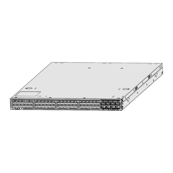
The RG-S6580-48CQ8QC switch is a next generation, data-center-oriented, high-density programmable 100G access switch independently developed by Ruijie Networks , providing 100G/400G access, low latency, and complete data center features. With up to 48 100GE ports and eight 400GE ports, the switch can be used with the RG-S6980-64QC switch to form a high-performance and high-reliability data center network. -
Page 6: Product Appearance
Power cords should be connected to a grounded output socket. The model of built-in lithium batteries of the RG-S6580-48CQ8QC switch is CR2032. The switch may explode if a wrong battery model is used. Used batteries should be properly disposed of. - Page 7 QSFP-DD Port Status LED Fan Status LED QSFP-DD Port Locator LED 10. Asset Tag The RG-S6580-48CQ8QC switch supports 400G QSFP-DD modules and 100G DSFP modules. Back Panel Figure 1-3 Back Panel of the S6580-48CQ8QC Switch Notes: Power Supply Module Slot USB 2.0 Port...
-
Page 8: External Ports
To protect the data and avoid device damage, use qualified USB flash drives from well-known vendors . The local USB port is compatible with most of the USB controllers except some USB flash drives. The RG-S6580-48CQ8QC switch supports system debugging, configuration, maintenance, management and host software uploading through the Console port. - Page 9 Hardware Installation and Reference Guide Product Overview Panel Status Meaning Identification (Front panel) (1) One of the modules of the system fails. (2) The internal or partial temperature exceeds the Solid red warning working temperature. (3) One power supply module is in position but not be powered up.
-
Page 10: Power Supply
1.1.6 Heat Dissipation The working temperature of the RG-S6580-48CQ8QC switch is 0° C to 40° C, or 32° F to 104° F. Heat dissipation design needs to ensure the stability, safety, and maintainability in such environment. The RG-S6580-48CQ8QC switch adopts fan ventilation and forced convection to ensure the device can work normally in specified environment. - Page 11 Hardware Installation and Reference Guide Product Overview Figure 1-6 M1HFAN II-F Module Notes: Status LED Handle of the fan module Table 1-4 LED Panel Status Description Identification The fan module is not powered on. Blinking green. The fan module is initializing. Status LED Status Solid green...
- Page 12 (W x D x H) 1.2.2 RG-PA1200I-F The RG-PA1200I-F module is the power supply module of the RG-S6580-48CQ8QC switch. The smart RG-PA1200I-F can obtain the power status, output power, output current and operating temperature in real time. The RG -PA1200I-F module supports both AC and HVDC input.
- Page 13 Hardware Installation and Reference Guide Product Overview Panel Status Description Identification When problems such as high power, high current, Blinking orange high temperature or low fan speed occurs, the power supply has a warning but keeps working. Technical Specifications of the Power Supply Module Table 1-8 Technical Specifications of the Power Supply Module Model RG-PA1200I-F (AC input)
-
Page 14: Preparing For Installation
Hardware Installation and Reference Guide Preparing for Installation 2 Preparing for Installation 2.1 Safety Precautions To avoid body injury and device damage, please carefully read the safety precautions before you install a S6580 series switch. The following safety precautions do not cover all possible dangers. Do not use the switch in a place where children may appear. -
Page 15: Laser Safety
Static electricity on clothing cannot be prevented . 2.1.5 Laser Safety Among the modules supported by the RG-S6580-48CQ8QC, there are a great number of optical modules that are Class I laser product. -
Page 16: Installation Site Requirements
2.2.2 Ventilation Requirements For the RG-S6580-48CQ8QC switch, leave sufficient space in the front and at the back of the chassis (at least 20cm) for ventilation. After various cables are connected, bundle the cables or place them in the cable management bracket to avoid blocking air inlets. -
Page 17: Cleanliness Requirements
2.2.5 System Grounding Requirements A good grounding system is the basis for the stable and reliable operation of the RG-S6580-48CQ8QC. It is the key to prevent lightning stroke and resist interference. Please carefully check the grounding conditions on the installation site according to the grounding requirements, and perform grounding properly as needed. -
Page 18: Emi Consideration
The grounding resistance should be smaller than 1 ohm. The RG-S6580-48CQ8QC switch has two grounding lugs on the right side of the chassis. The grounding lugs are indicated by prominent warning labels. -
Page 19: Installation Tool
Dust-free paper, fiber end-face microscope Meter Multimeter, bit error rate tester (BERT), optic-power meter The RG-S6580-48CQ8QC switch is delivered without a tool kit. The tool kit is customer-supplied. 2.5 Unpacking and Checking Unpacking Procedure Use scissors to cut the packing straps off the shipping container, place the container on a flat surface with the top of the container facing upwards, and check whether the seal label on the top of the shipping container is intact. -
Page 20: Installing The Switch
Installing the Switch 3 Installing the Switch The RG-S6580-48CQ8QC switch must be used and fixed in the room. Make sure you have carefully read Chapter 2, and be sure that the requirements in Chapter 2 have been met. 3.1 Installation Procedure... -
Page 21: Before You Begin
Hardware Installation and Reference Guide Installing the Switch Prepare for installation Prepare for installation Install the cabinet Ground the switch Mount the switch into the cabinet Connect the power supply Install the modules Connect the cables Bundle the cables Verify the installation 3.2 Before You Begin Carefully plan and arrange the installation location, networking mode, power supply, and wiring before installation. -
Page 22: Mounting The Cabinet
Hardware Installation and Reference Guide Installing the Switch The installation location meets the temperature and humidity requirements of the equipment. The qualified power supply and current required are available at the installation location. The related network cables have already been deployed at the installation location. 3.3 Mounting the Cabinet Precautions When you install the cabinet, pay attention to the following requirements:... - Page 23 The RG-S6580-48CQ8QC switch is EIA-compliant and can be installed in a 19 RU rack. During installation, keep the front panel of the switch forward. You are advised to use a tray to hold the RG-S6580-48CQ8QC switch and secure the tray on the bracket, or use the rear bracket provided with the switch.
- Page 24 Hardware Installation and Reference Guide Installing the Switch The rack-mount brackets must be screwed to four of the six screw holes at both sides on the back panel of the switch. Distinguish the left and the right rear brackets according to the marked directions. The rear brackets provided are only applicable for racks with a depth from 800 mm to 1200 mm (37.50 in.
- Page 25 Hardware Installation and Reference Guide Installing the Switch PGNDs are installed on a side of the chassis. First connect the PGND to the grounding lug of the rack and then connect the grounding lug to the grounding bar of the equipment room. Installation steps are as follows: (1) Attach two grounding studs to the switch.
-
Page 26: Installing And Removing A Fan Module
Hardware Installation and Reference Guide Installing the Switch A service person should check whether or not the socket-outlet from which the device is to be powered provides a reliable connection to the building protective earth. If not, the service person should arrange for the installation of a protective earthing conductor from the separate protective earthing terminal to the protective earth wire in the building. - Page 27 Hardware Installation and Reference Guide Installing the Switch 3.7 Installing and Removing a Power Module Wear anti-static gloves before the following operations. Installing a Power Supply Module Take a power supply module out of the package and check whether the input mode and the input parameters of the power supply module meet the requirements.
- Page 28 Hardware Installation and Reference Guide Installing the Switch Remove the RG-PA1200I-F power supply module uprightly and slowly. Install a filler panel in the location where the power supply module is removed to ensure the normal ventilation and dissipation and avoid the dust in the chassis. 3.8 Installing and Removing Swappable Interface Modules To avoid damaging components due to installation errors, make sure that the switch is mounted before SFP modules are installed.
- Page 29 Hardware Installation and Reference Guide Installing the Switch Push the module gently into the DSFP module slot until you hear a click. This indicates the module is correctly installed. A module with clips is shown in Figure 3-9. Figure 3-9 Installing a DSFP Module Notes: DSFP port DSFP module...
- Page 30 Hardware Installation and Reference Guide Installing the Switch Notes: DSFP port DSFP module Unplug the fiber-optic cable before removing the SFP module. Do not pull out the SFP module forcefully without turning down its handle. Cover SFP ports and fiber ports with dust plugs in time to prevent dust. 3.8.2 Installing a 400GE QSFP-DD Module To avoid damaging components due to installation errors, check the position of the 400GE DSFP module in Figure 3-8 and read this section carefully before installing a 400GE QSFP-DD module.
-
Page 31: Connecting The Console Port
Hardware Installation and Reference Guide Installing the Switch After the patch cord is connected to the QSFP-DD module, the Link/ACT LED of the QSFP-DD port is on. Otherwise, please check connection of the patch cord. An SFP module cannot be inserted inversely. See Figure 3-11 for the direction to insert a QSFP-DD module. If the SFP module cannot be inserted to the end, do not push it forcefully. -
Page 32: Binding The Cables
Hardware Installation and Reference Guide Installing the Switch Precautions Correctly distinguish single-mode and multi-mode fibers and ports. Avoid bends of small curvature at the connector. Connection Steps Connect one end of the RJ45 connector to the Ethernet MGMT interface of the device board, and the other end to the NMS or a control terminal Insert the single-mode or multi-mode fiber into the appropriate interface according to the identification on the panel of the line card. - Page 33 Hardware Installation and Reference Guide Installing the Switch Verify that the fibers and twisted pairs match the ports. Verify that the cables have been bound properly. Verify that the cabling specification and connecting method are correct. Verify that the cablings are all indoor.
-
Page 34: Setting Up The Configuration Environment
Hardware Installation and Reference Guide Verifying Operating Status 4 Verifying Operating Status 4.1 Setting up the Configuration Environment Setting up the Configuration Environment Connect the PC to the Console port on your switch by using an Ethernet cable. Figure 4-1 Setting up the Configuration Environment Connecting the Console Cable Connect one end of the DB-9 jack of the console cable to the serial port of the PC. - Page 35 Hardware Installation and Reference Guide Verifying Operating Status (3) Enter the name of the new connection and click OK. A window appears as shown in Figure 4-3. In the column of Connect Using field, select the serial port you want to use. Figure 4-3 (4) After the serial port is selected, please click OK.
-
Page 36: Powering On The Switch
Hardware Installation and Reference Guide Verifying Operating Status (5) After the serial port parameters are set, click OK to enter hyper terminal window. 4.2 Powering on the Switch Checklist before Power-on Check if the switch is fully grounded. Check if the fan module and the power supply module are correctly installed. -
Page 37: Monitoring And Maintenance
5 Monitoring and Maintenance 5.1 Monitoring LEDs When the RG-S6580-48CQ8QC is running, you can monitor the status of the switch and each module by observing the LEDs. If the Status LED is red, it indicates that the system is faulty. You are advised to log in to the software management system to troubleshoot the fault. - Page 38 Replacing Lithium Battery The built-in lithium batteries can support the real time clock of the RG-S6580-48CQ8QC switch without external power supply. Please contact Ruijie Networks Customer Service Department for replacing lithium batteries. The technical support personnel of Ruijie Networks will replace the battery with the same model.
-
Page 39: Troubleshooting
Hardware Installation and Reference Guide Troubleshooting 6 Troubleshooting 6.1 General Installation Troubleshooting Procedure... - Page 40 Check the installation of the power supply module Check the connector of each module Check the installation of other modules Check the LEDs on the device Check serial port connection and parameters Check the cable connection Contact Technical Support of Ruijie Networks...
-
Page 41: Common Troubleshooting Procedures
Check whether serial port cables are connected correctly, whether serial port cables are disconnected, and whether the connected serial port is identical with that configured on the hyper terminal. If there is still no serial port printed information, please contact Ruijie Customer Service Department for technical support. Fault 5: The serial port console outputs illegible characters. - Page 42 Check whether the module is inserted correctly. If the newly-inserted module still cannot be powered on even though the checking is ok, please contact Ruijie Customer Service Department for technical support. Fault 7: The link cannot be set up between fiber interfaces [Fault Description] The system runs normally.
-
Page 43: Appendix A Connectors And Connection Media
Hardware Installation and Reference Guide Appendix A Connectors and Connection Media Appendix A Connectors and Connection Media 10GBASE-T/1000BASE-T/100BAS E-TX Port The 10GBASE-T/1000BASE-T/100BASE-TX port t supports auto-negotiation at three rates, and automatic MDI/MDIX Crossover at these three rates. 10GBASE-T complies with the IEEE 802.3an standard. Supported cables and cabling distances are listed in the following table. - Page 44 Hardware Installation and Reference Guide Appendix A Connectors and Connection Media (4) The suggested number of wires in a bundle is not more than 12. (5) CAT6 wire connector is replaced with CAT6A wire connector The 1000BASE-T complies with IEEE 802.3ab standard, and up to 100 m (328.08 feet) of 100-ohm CAT5, CAT5E or twisted pairs with higher standard should be used.
- Page 45 Hardware Installation and Reference Guide Appendix A Connectors and Connection Media For the fiber ports, select single-mode or multiple-mode fiber-optic cables for connection according to the fiber module connected. The connection of fiber-optic cables is shown in Figure A-4: Figure A-4 Fiber-Optic Cable Connection...
-
Page 46: Appendix B 100Ge And 400Ge Modules
Hardware Installation and Reference Guide Appendix B 100GE and 400GE Modules Appendix B 100GE and 400GE Modules We provide 100GE DSFP modules, 400GE QSFP-DD modules and AOC modules according to the interface type of the switch module. You can select modules to suit your specific needs. The following models and technical specifications of 100GE DSFP modules, 400GE QSFP-DD modules and AOC modules are listed for your reference. -
Page 47: Appendix C Lightning Protection
Hardware Installation and Reference Guide Appendix C Lightning Protection Appendix C Lightning Protection Installing AC Power Arrester (lightning protection cable row) The external lightning protection cable row should be used on the AC power port to prevent the switch from being struck by lightning when the AC power cable is introduced from the outdoor and directly connected to the power port of the switch. - Page 48 Hardware Installation and Reference Guide Appendix C Lightning Protection Tools: Cross or straight screwdriver, Multimeter, Diagonal pliers Installation Steps: Tear one side of the protection paper for the double-sided adhesive tape and paste the tape to the framework of the Ethernet port arrester.
- Page 49 Hardware Installation and Reference Guide Appendix C Lightning Protection Reversed direction of the arrester installation. You shall connect the external network cable to the “IN” end and connect the switch Ethernet port to the “OUT” end. Poor arrester grounding. The length of the grounding line should be as short as possible to ensure that it is in good contact with the switch grounding terminal.
-
Page 50: Appendix D Cabling Recommendations In Installation
Hardware Installation and Reference Guide Appendix D Cabling Recommendations in Installation Appendix D Cabling Recommendations in Installation When the switches are installed in standard 19-inch cabinets, the cables are tied in the binding rack on the cabinet by the cable management bracket, and top cabling or bottom cabling is adopted according to the actual situat ion in the equipment room. - Page 51 Hardware Installation and Reference Guide Appendix D Cabling Recommendations in Installation Cables of different types (such as power cords, signal cables, and grounding cables) should be separated in cabling and bundling and no mixed bundling is allowed. When they are close, crossover cabling can be adopted. In the case of parallel cabling, power cords and signal cables should maintain a distance not less than 30 mm (1.18 in.).
- Page 52 Hardware Installation and Reference Guide Appendix D Cabling Recommendations in Installation Figure D-3 Bundling up cables (3) Cables not to be assembled or remaining parts of cables should be folded and placed in a proper position of the cabinet or cabling slot. The proper position indicates a position that will not affect device running or cause device damage or cable damage during commissioning.
- Page 53 Hardware Installation and Reference Guide Appendix D Cabling Recommendations in Installation Figure D-4 Cable fastening The hard power cable should be fastened at the terminal connection area to prevent stress on terminal connection and cable. Do not use self-tapping screws to fasten terminals. Power cables of the same type and in the same cabling direction should be bundled up into cable bunches, with cables in cable bunches clean and straight.
-
Page 54: Appendix E Site Selection
Hardware Installation and Reference Guide Appendix E Site Selection Appendix E Site Selection The machine room should be at least 5 km (3.11 miles) away from the heavy pollution source such as the smelter, coal mine and thermal power plant, 3.7 km (2.30 miles ) away from the medium pollution source such as the chemical industry, rubber industry and electroplating industry, and 2 km (1.24 miles) away from the light pollution source such as the food manufacturer and leather plant.
Need help?
Do you have a question about the RG-S6580-48CQ8QC and is the answer not in the manual?
Questions and answers