Table of Contents
Advertisement
Advertisement
Table of Contents

Related Manuals for Lifan KP4500iE


Summary of Contents for Lifan KP4500iE
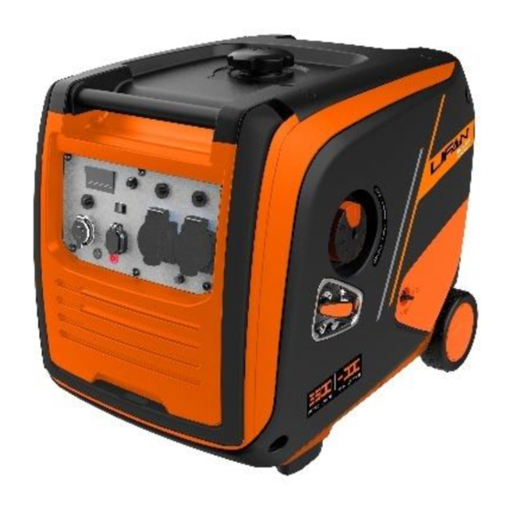
- Page 1 LIFAN SILENT INVERTER GENERATOR KP4500iE Owner’s Manual...
- Page 2 Thank you for choosing a Lifan Inverter Generator. This manual covers the correct operation and maintenance. Before operating the generator, it is advised the user carefully reads and fully understands these instructions At the time of publication, all technical data and drawings in this manual are consistent with the latest product.
-
Page 3: Safety Warning
Safety Warning The safety of you and other users is very important. Please carefully read and understand the extremely important safety warnings described in the manual and on the labels of the generator set. Safety warnings alert you to potential dangers that may harm you and others. -
Page 4: Table Of Contents
Contents Safety Warning ............... 3 Content ................... 4 1.Safety Instruction ..............6 1.1 Safety Specification ............6 1.2 Special Information ............8 2. Safety Warning Label ............9 3 . Components Identification ........... 1 0 3.1 Components Feature ..........10 3.2 Control Panel .............. - Page 5 6.1 Connect to Household Power Supply ....... 21 6.2 Generator Grounding ........... 22 6.3 AC Power ..............22 7. Starting the Engine ............25 7.1 Recoil Start ..............25 7.2 Electric Start ..............25 7.3 Remote Start ............... 27 8 . Stopping the Engine ............32 9 .
-
Page 6: Safety Instruction
1.0 Safety Instructions 1.1 Safety Specification Please read the manual carefully to familiarise yourself with the generator and its components before operating. Familiarity with the safe operating procedures of generators can help you avoid accidents. Do not use in wet or damp Do not use indoors conditions Do not connect directly to... - Page 7 Take care not to spill fuel Stop the engine before when refuelling refuelling Place inflammable materials at least 1m away from the unit...
-
Page 8: Special Information
1.2 Special Information Electrical equipment includes unexposed wires and plugs The protecting breaker should be matched with generator The application parameters and performance should be totally matched if changing. Ensure the unit is well grounded before using Extension wires must meet the specification as follows: Ø... -
Page 9: Safety Warning Label
2.0 Safety Warning Label Please read the manual carefully before using. Safety warning label... -
Page 10: Components Identification
3.0 Components Identification 3.1 Components... -
Page 11: Control Panel
3.2 Control Panel The factory may adjust the position and design of the panel to suit different applications. Please note that this is subject to change without prior notice 4 500iS/ 4500iE Digital meter ECO (Economy control system) Reset button AC protector/breaker DC protector DC Socket... -
Page 12: Type And Serial Number
3.3 Type and Serial Number Location... -
Page 13: Control System
4.0 Control System 4.1 Low oil warning system (YELLOW) The low engine oil protection system will automatically stop the engine once the oil level drops below the required minimum amount. The Low oil indicator light will remain illuminated until the generator is refilled with the correct amount of oil. -
Page 14: Ac Indicating Light (Green)
3. Check whether there is a foreign body blocking the air inlet or if there is any abnormality with the relevant control parts and eliminate if necessary. 4. After checking, press the voltage recovery button for 1-3 seconds and restart. Notice: When using electrical equipment with a high start-up current such as compressors or submersible pumps, the overload indicating light may flash for few seconds however... -
Page 15: Ground/Earth Terminal
4.5 Ground/Earth Terminal The ground/earth terminal is designed to be connected to the ground wire to prevent electric shock. When electrical equipment is grounded, the generator must also be grounded. 4.6 AC Breaker Protector Switch The AC Breaker protector will automatically stop the generator if an AC short circuit or overload occurs. -
Page 16: Preparation
5.0 Preparation 5.1 Fuel Fuel is flammable and toxic. Please read the safety instructions very carefully before attempting to refuel the generator. (See Pages 6/7 for details.) Do not overfill the tank with fuel otherwise it will overflow when the generator gets hot Once refuelling is complete, ensure the fuel filler cap is replaced securely Fuel tank... -
Page 17: Engine Oil
5.2 Engine Oil The generator is shipped dry, without engine oil. Please do not attempt to start it before adding the correct grade and amount of oil. 1. Place the generator on a level surface 2. Turn the knob ① to “ON”, and pull down the oil maintenance cover ②... -
Page 18: Recoil Starter
4. Fill with the recommended grade and amount of oil, replace and tighten the oil filler cap 5. Replace oil maintenance door and turn knob to “OFF” position 5.3 Recoil Starter Pull the starter handle up gently until resistance is felt, then pull it firmly to start the engine... -
Page 19: Fuel Tap
5.4 Fuel Tap Fuel tap is a device that controls the flow of fuel from the tank to the carburettor. Please ensure the 3 in 1 control knob is set to the “OFF” position when not in use. -
Page 20: Choke Valve
5.5 Choke Valve The choke is designed to restrict the air flow to the carburettor, providing a richer fuel mixture which enables the engine to be started easily in cold conditions. When starting from cold, select the "CHOKE" (start) position on the 3 in 1 control knob. Once running and engine is warm, set and leave the 3 in 1 control knob to the “RUN”... -
Page 21: Generator Use
6.0 Generator Use Applicable temperature:-5°C~40°C Applicable humidity: Below 95% Applicable altitude: Areas below 1000m (If you intend to operate your engine at altitudes above 1000m, reduce the engine power or modify the carburettor by contacting the suppliers. 6.1 Connect to Home/Mains power Connecting to the home/mains system as a standby power supply should only be undertaken by a fully qualified electrical engineer as this task involves fitting specialist... -
Page 22: Generator Grounding
6.2 Generator Grounding In order to prevent the generator from being damaged by electric shock or misuse of inferior electrical appliances, the generator should be grounded/earthed by a good insulated conductor 6.3 AC Power Before starting the generator, please check the following: The total power of all electrical appliances (the sum of resistance, capacitance and inductive load) shall not exceed the rated power of the generator. - Page 23 Generally speaking, capacitive and inductive loads, especially motor drive devices, will require a large starting current when starting. The following table is for your reference when connecting these electrical appliances to the generator set. This engine may require a high-altitude carburettor kit to ensure correct engine operation at altitudes above 1000m.
- Page 24 Even with a suitable carburettor, the power of the petrol engine will decrease by about 3.5% for every 300m above sea level. If the carburettor is not replaced properly, the decline will be even greater. If the generator has been modified with the carburettor for high-altitudes and then used at normal altitude without reverting to the normal carburettor, it will produce an excessive lean mixture causing overheating or serious...
-
Page 25: Starting The Engine
7.0 Starting the Engine 7.1 Recoil Start 1. Remove all loads from the output end 2. Rotate the 3 in 1 control knob to the "Choke" position 3. Turn the AC protector/Breaker to “Off” 4. Pull the recoil starter slowly until compression is felt, then pull it briskly. - Page 26 1. Remove all loads from the output end 2. Rotate the 3 in 1 Control Knob to the “Choke” position。 3. Turn the AC Protector/Breaker to “Off” 4. Press the “On” button 5. After starting the engine, set the 3 in 1 Control Knob to the “Run”...
-
Page 27: Remote Start
7.3 Remote Start 1. Confirm whether the load is within the rated power range of the generator 2. Rotate the start switch to place the start button in the "run" position a. Fuel System on b. Ignition system on c. Remote control power on 3. - Page 28 The lithium-ion battery is required to store no more than 50% of its capacity when it leaves the factory. Before attempting to use the electric start function, start the engine manually by following instructions in 7.1 and allow the generator to run continuously for more than 2 hours to complete the charging, otherwise the service life of the battery will be shortened.
- Page 29 send it to a special maintenance point for inspection and maintenance 3. If the generator is not being used for long periods, please fully charge the battery before disconnecting the negative pole of the battery connection. Store the unit in a dry and cool place.
- Page 30 b. Connect an external DC12v power supply or 12v Battery parallel to the battery of the generator set Firstly, remove the bolts and cover from the left-hand side to allow access. Connect the back-up DC12v battery or DC12v power supply to the battery terminal in parallel.
- Page 31 Please note: If the external power supply specification is higher than the DC12v battery that comes with the unit, it may be started by hand, electric start or remote control. If the power specification of the external source is less than the original generator battery, the current it provides will not be enough to start the generator.
-
Page 32: Stopping The Engine
8.0 Stopping the Engine 1. Turn the ECO switch to “OFF” 2. Turn off the AC Breaker 3. Turn the engine switch to “OFF” 4. Disconnect any electric devices To stop the engine in an emergency, turn the Engine Switch to the “OFF" position. -
Page 33: Maintenance
9.0 Maintenance Safety is an obligation of the owner. Periodic inspection, adjustment and lubrication will keep your generator in the safest and most efficient condition possible. In order to keep the engine in good condition, you must check and maintain it regularly. Please follow the schedule below. Maintenance Schedule... - Page 34 (1) Maintain more frequently when being used in dusty or unusually wet areas. (2) These items should be serviced by your servicing dealer, unless you have the proper tools, data and technical skills. ● If you often work at high temperature or high load, you should replace the engine oil every 10 hours.
-
Page 35: Engine Oil Replacement
9.1 Engine Oil Replacement Please drain the engine oil when the engine is still warm (not hot). This enables the oil to be discharged quickly and cleanly. ① Remove oil level gauge and ten turn open the oil drain bolt and drain the oil. ②... -
Page 36: Air Filter Maintenance
9.2 Air Filter Maintenance A dirty air filter will affect the flow of air into the carburettor. To prevent carburettor breakdown, the air filter should be regularly maintained. If it is used in dusty environment, it should be maintained more frequently. Cleaning the filter element with gasoline or flammable solvents may cause fire or explosion. -
Page 37: Spark Plug
9.3 Spark plug Please replace the spark plug according to the original type: F7TC 1. Remove the spark plug cap 2. Use the spark plug socket wrench to remove the spark plug 3. Visually inspect whether the spark plug insulator is damaged. Replace the spark plug if it is damaged 4. -
Page 38: Storing
10.0 Storing avoid combustion misfire contact with high-temperature components, the generator must be allowed to cool before packaging and storage. If long-term storage is planned, please make sure the storage area is clean and dry. 1. Drain the fuel from the fuel tank. Clean the fuel filter, O- ring seal and precipitation cup after the assembly. -
Page 39: Troubleshooting
11.0 Troubleshooting Engine does not start... -
Page 40: Circuit Diagram
12.0 Circuit Diagram... -
Page 43: Technical Specifications
13.0 Technical Specification...
Need help?
Do you have a question about the KP4500iE and is the answer not in the manual?
Questions and answers