
Related Manuals for Avery Weigh-Tronix ZM510


Summary of Contents for Avery Weigh-Tronix ZM510
- Page 1 CONFIDENTIAL ZM510 Indicator Service Manual original instructions AMERICAS AWT35-501664 Issue AB...
- Page 2 This publication was correct at the time of going to print, however Avery Weigh-Tronix reserves the right to alter without notice the specification, design, price or conditions of supply of any product or service at any time.
-
Page 3: Table Of Contents
Chapter 6 ADMIN Menu ........................... 27 Calibrate ........................... 29 Zero procedure ......................29 Span procedure ......................30 Linearity (Linear) procedure ..................31 Input procedure ......................31 Gravity procedure ...................... 31 Display procedure ..................... 32 Cal Unit procedure ....................32 ZM510 Indicator Service Manual... - Page 4 Standard Scale Response Message ................. 58 Unrecognized Command Response ................. 58 About Command Response ..................58 Scale Information Command Response ..............59 Avery Weigh-Tronix Extended SMA Commands ............60 ENQ & B-Cast commands ....................62 NCI commands ........................ 63 PLC Configuration information ..................64 ModBus/TCP ......................
- Page 5 Additional token tables ....................107 Network tokens ......................108 ASCII characters (UNI-code UTF-8) ................111 Control codes ......................... 112 Chapter 12 ZM510 Menus ........................113 Chapter 13 Technical illustrations ....................... 115 Exploded drawing ......................115 Parts Kits ........................116 Panel mount exploded drawing ..................117 Panel Mount kits ............................
- Page 6 External Opto I/O Cards ....................125 Index ............................... 127 ZM510 Indicator Service Manual...
-
Page 7: Manual Revision History
Manual revision history Current Date Created Details of Changes Issue May 2017 New manual June 2017 Correction on page 81. ZM510 Indicator Service Manual... - Page 8 ZM510 Indicator Service Manual...
-
Page 9: Chapter 1 General Information And Warnings
Cautions give information about procedures that, if not observed, could result in damage to equipment or corruption to and loss of data. NOTE: This is a Note symbol. Notes give additional and important information, hints and tips that help you to use your product. ZM510 Indicator Service Manual... -
Page 10: Installation
On the aluminum and panel mount models the shield wires should be connected to the SHLD connection on the corresponding terminal block connectors. ZM510 Indicator Service Manual... -
Page 11: Safe Handling Of Equipment With Batteries
1.2.5 Panel mount scale interface cable installation The ZM505 panel mount assembly include the AWT25-501388 ferrite. Installing the ferrite on the scale interface cable on the panel mount models assists with eliminating potential noise captured by the scale interface cable. ZM510 Indicator Service Manual... -
Page 12: Routine Maintenance
Application and usage will determine the frequency of calibration required for safe operation. Always turn off the machine and isolate from the power supply before starting any routine maintenance to avoid the possibility of electric shock. ZM510 Indicator Service Manual... -
Page 13: Cleaning The Machine
Classe A prescrites dans le Règlement sur le brouillage radioélectrique edicté par le ministère des Communications du Canada. European Countries WARNING: This is a Class A product. In a domestic environment, this product may cause radio interference in which the user may be required to take adequate measures. ZM510 Indicator Service Manual... -
Page 14: Chapter 2 Introduction
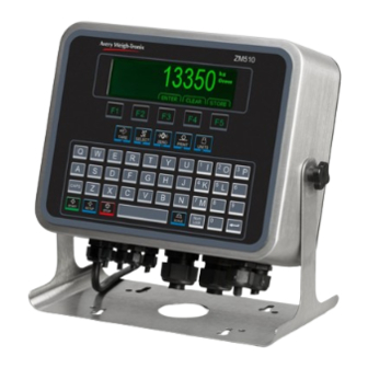
Figure 2.1 shows the front panel of the ZM510 indicator which consists of the keys and the graphic display. Figure 2.1 ZM510 front panel Never press a key with anything but your finger. Damage to the overlay may result if sharp or rough objects are used. -
Page 15: Front Panel Keys
Front Panel Keys 2.1 Front Panel Keys The key functions for the ZM510 are listed below. Press the TARE key to perform a pushbutton tare function. Acts as an up arrow key for menu navigation. TAR E Press the SELECT key to toggle between the active display values. -
Page 16: Display
Audit Setup Diag Figure 2.2 Top level menu The other icons in the menu do not have this highlight. See the illustration below. Setup Setup Not selected Selected The next chapters cover the menus in detail. ZM510 Indicator Service Manual... -
Page 17: Chapter 3 Introduction To The Menus
SEL EC T ZER O PR IN T U N ITS DOWN ENTER LEFT RIGHT Figure 3.1 Navigation keys Another ENTER key can also be found in the lower right corner of the alphanumeric keypad, shown below. ZM510 Indicator Service Manual... -
Page 18: Exiting A Menu
Use the Up or Down key to make your choice and press the ENTER key to accept. The indicator will reboot and return to the startup screen with the new changes active. ZM510 Indicator Service Manual... -
Page 19: Chapter 4 User Level Menu
• Print Key in Displays • Style • Style Site ID Seal • Port 1 number status • Port 2 • Port 3 • USB Archive menu item appears only if enabled in the ADMIN>System menu. ZM510 Indicator Service Manual... -
Page 20: About Menu
• Version • Version • Version indicator • Bus 2 • Subnet • dSerial • SW Part • Gateway • Card 1 • Version • MAC • Card 2 • Cur.Ser • Cal.Ser • Type • Version ZM510 Indicator Service Manual... - Page 21 Version - View the firmware version of the cell that is connected. Cur. Ser - View the serial number of the cell that is connected. Cal. Ser - View the serial number of the cell that WAS connected at the time of calibration. ZM510 Indicator Service Manual...
-
Page 22: Audit Menu
Under Port 3 choose to print to a column or ticket printer. Printing to USB requires that a USB flash drive is connected to the indicator host USB. Printing to USB will create a folder on the flash drive and a comma separated file with the data. ZM510 Indicator Service Manual... -
Page 23: Chapter 5 Diagnostics Menu
Clear the zero offset to return the indicator to calibration zero. Choose Yes or No. This can restore the original calibration zero point if the ENTER key is accidentally pressed when a tank or vessel contains product that cannot be emptied. ZM510 Indicator Service Manual... -
Page 24: Display
In 000 is displayed, if no inputs are jumpered. To test input 1, jumper pins 1 and 2 of the I/O connector on the indicator … The first digit becomes 1 until the jumper is removed. ZM510 Indicator Service Manual... -
Page 25: Outputs
The logs report will be a printout of overloads and underloads that have occurred. Logs These are logs of overload and underload conditions experienced by the scale. You can print them or clear them from memory. ZM510 Indicator Service Manual... -
Page 26: Options
10% of each other. As weight increases the tension frequency should increase and the compression frequency should decrease. 5.11 DigJbox This item not valid in the America’s market. This completes the Diag menu. To exit the menu, see Exiting a menu on page ZM510 Indicator Service Manual... -
Page 27: Chapter 6 Admin Menu
• Out • Type • D-Bits • Bind • Beeper • Type • Roc • Parity • Config (depending on selection) • Num Scl • DigJbox • S-Bits • Traffic • C-trol Figure 6.1 ADMIN menu map ZM510 Indicator Service Manual... - Page 28 The top level of the Setup menu is displayed. Follow the normal navigation rules to move through the items in this menu. Each item is explained below. See Figure 6.3. Setup Calib Scale System Ports Figure 6.3 Setup menu top level ZM510 Indicator Service Manual...
-
Page 29: Calibrate
See LAST procedure on page CAL.ZERO procedure Highlight Cal.Zero and press ENTER … The CALIBRATE window appears. Empty the scale and press ENTER … Busy is briefly shown then the weight is displayed. ZM510 Indicator Service Manual... -
Page 30: Span Procedure
Place the test weights equal to the calibration weight value on the scale and press ENTER … Busy is briefly displayed then the CALIBRATE screen with the span weight displayed. Press ENTER to accept the span … The screen returns to the home calibration screen. ZM510 Indicator Service Manual... -
Page 31: Linearity (Linear) Procedure
0 to 90. A positive value works for north or south of the equator. This stands for altitude. Key in the altitude for the installation site. The valid range is 0 to 30,000 ft. (10000 m). ZM510 Indicator Service Manual... -
Page 32: Display Procedure
Some parameters may be set automatically by your choice of SitE in the System menu item. Use the Scale menu to configure the scale operating parameters such as capacity and division size, etc. See the full list in Figure 6.5. ZM510 Indicator Service Manual... -
Page 33: Capacty
4 . You can assign any of the following units of measure to any of the units: Lb , 1000 g , oz , gr , lb-oz , Cust 1 , Cust 2 , Cust 3 , Cust 4 or Off . ZM510 Indicator Service Manual... -
Page 34: Stable
Use this to filter out vibrations affecting the scale. Under this item you have the following three parameters to set. This stands for average. 10 is the default value. Const This stands for constant. 1 is the default value. ZM510 Indicator Service Manual... - Page 35 After the Const value is established you may wish to lower the Avg value to improve display response time. ZM510 Indicator Service Manual...
-
Page 36: Ranges
(and increasing weight) values between 0 and the Cap 1 will use Div 1 as the division size, values between Cap 1 and Cap 2 will use Div 2 as the division size, and values above Cap 2 will use the division size entered in Dvision on page ZM510 Indicator Service Manual... -
Page 37: Type
This stands for Rate of Change. Use this to set the parameters to calculate rate of change for flow rates or weight/time applications. Settings available are: Period Enter a value for the period of time to calculate Roc. ZM510 Indicator Service Manual... -
Page 38: Digjbox
- See Password on page 44 • Z-Lock - See Z-Lock on page 44 • Beeper - See Beeper on page 44 • Num Scl - See Num Scl on page 45 Figure 6.6 System menu ZM510 Indicator Service Manual... -
Page 39: Site
Default settings may need to be changed to meet local agency requirements 6.3.2 Display Use this to set the following parameters for the display. Dec.Pt This configures whether a decimal point or comma is used to separate whole and fractional numbers. ZM510 Indicator Service Manual... -
Page 40: Buttons
Activate this to see the transaction count value. Count Activate this to see the count value. Pc Wt Activate this to see the piece weight value. A2D Cnt Activate this to see the A to D count value. ZM510 Indicator Service Manual... - Page 41 Activate this to see the future gross value (#2). This represents a predicted Fut Gr2 gross weight calculated by multiplying the current rate by the free fall time and adding the result to the current gross weight: Future Gross = Rate X Free Fall + Gross ZM510 Indicator Service Manual...
-
Page 42: Tare
Choose On to enable high resolution tare or Off to disable high resolution tare. Default is Off . If preset tare is enabled, pushbutton tare and keyboard entry tare will be disabled automatically. ZM510 Indicator Service Manual... -
Page 43: Config
Use this to record the serial number of the indicator. The serial number is located on the label attached to the indicator. To enter the serial number enter the first four digits, press ENTER and enter the last five digits and press ENTER again to accept. ZM510 Indicator Service Manual... -
Page 44: Update
Use this to set the time value, in minutes, for this function. 60 minutes is the default. 6.3.12 Beeper Use this to enable or disable the beeper sound when you press keys. on is the default. ZM510 Indicator Service Manual... -
Page 45: Num Scl
PC serial port or print busy output on a Line or Lister printer. Soft Stands for software handshaking. This allows a device to start and stop the indicator transmit by sending Xon or Xoff characters. ZM510 Indicator Service Manual... - Page 46 (Consult the site IT specialist) Key in each octet and press ENTER to accept it. ZM510 Indicator Service Manual...
- Page 47 1 to 65535. If Type is set to UDP UDP stands for User Datagram Protocol. Type x , Port x , LcPrt x , RxAdd x , TxAdd x and DynTX x are displayed. These are explained below. ZM510 Indicator Service Manual...
-
Page 48: Protcl
Which Attributes and Bindings apply to the selected Type will be described in the detailed descriptions below. Type x - Choose the method to send and receive data for Protocol x, where x = 1 to 15. None Choose this to disable the selected protocol. ZM510 Indicator Service Manual... - Page 49 This can only be configured via Ztools. See the warning below. WARNING: If using Input Interpreter, do NOT change to another TYPE from the front panel or Input Interpreter will not be available without reconfiguring from Ztools. ZM510 Indicator Service Manual...
-
Page 50: Edit
In the Broadcast and Enquire Protocols this determines which scale the received commands refer to. 6.4.3 P.F. Edit This stands for print format editor. Please refer to the section Print formatting on page for the procedures to edit or create print formats. ZM510 Indicator Service Manual... -
Page 51: Plc
Then you will select the data type and then the network token you want assigned to that memory register. In 1-16 These are the 16 inbound data configuration memory registers. For each there are three choices: Type, Value and Scale. See the descriptions below: ZM510 Indicator Service Manual... -
Page 52: Printer
Prtr 1 You can choose to set up this printer or Prtr 2 . The setup procedure is the same. ZM510 Indicator Service Manual... -
Page 53: File
NUMBRD This will create new file appended with a sequential number for each transaction. This will create a new file and the file name will be appended with the date and time (including seconds) for each transaction. ZM510 Indicator Service Manual... -
Page 54: Options
DC Output 4 relays (3-60VDC) card DeviceNet (DevNet) © Profibus Depending on the choice made for Type , a Config menu may appear. Below are the Config and/or Calibration menus that will appear for the installed card. ZM510 Indicator Service Manual... - Page 55 If DeviceNet card is installed: Config Node 0-63 Baud Select from 125K, 250K or 500K. Rate Select 1, 2, 5, 10, or 20. If Profibus card is installed: Config Node 0-126 Rate Select 1, 2, 5, 10, or 20. ZM510 Indicator Service Manual...
- Page 56 TARE increase in small increments SELECT decrease in small increments PRINT increase in large increments UNITS decrease in large increments Press ENTER to complete the analog output calibration. ZM510 Indicator Service Manual...
-
Page 57: Chapter 7 Communication Port Protocols
See “Scale Information Command Response” Information data. (for the current scale) (below) <ESC> The indicator will reboot itself None SMA protocol is maintained by an external organization. For definitive and current details on this protocol go to www.scalemanufacturers.org. ZM510 Indicator Service Manual... -
Page 58: Standard Scale Response Message
1st response: <xxx> = “SMA” <yyyyy> = compliance level/revision 2nd response: <xxx> = “MFG” <yyyyy> = manufacturer 3rd response: <xxx> = “MOD” <yyyyy> = software part number 4th response: <xxx> = “REV” <yyyyy> = software revision ZM510 Indicator Service Manual... -
Page 59: Scale Information Command Response
<yyyyy> = “PTMCU” list of supported SMA commands. Level 1 commands are not included in the list. 6th response: <xxx> = “END” <yyyyy> = nothing 7th & more - responses: Subsequent N commands will return a ‘?’ response. Unrecognized Command Response ZM510 Indicator Service Manual... -
Page 60: Avery Weigh-Tronix Extended Sma Commands
7 Communication port protocols 7.1.6 Avery Weigh-Tronix Extended SMA Commands <LF>XA<CR> This will initiate an Accumulate command. It will perform an Accumulation transaction if all required conditions are met. The port that initiated the command will also receive an <LF>xa<CR> response. - Page 61 The indicator will get or return the value of the variable specified by the network token. A valid response is in the form of <LF><value><CR>. <LF>XG<n><CR> This will set the Active Scale. A valid response is in the form of <LF>xg<CR>. ZM510 Indicator Service Manual...
-
Page 62: Enq & B-Cast Commands
Performs same function as pressing the F5 key *Fires the event for the key. Upper or lower case characters will perform the same function. Only keys found on your model Z-series indicator front panel can respond as defined above. ZM510 Indicator Service Manual... -
Page 63: Nci Commands
If the PROT > ATTR > ENQ menu value is set to 100, to increase resolution by 100, you may add a 2 or 3 to the command to return a 2 or 3 character status byte. For example: 102 will increase resolution by 100 and return a 2 character status byte. ZM510 Indicator Service Manual... -
Page 64: Plc Configuration Information
40001 (i.e. Gross, Net, etc.) From PLC Output Read/Write 41025 (i.e. PB-Zero, Print, etc.) 2 Byte Example Indicator Data Type (out) ModBus Register SINT16 40001 SINT16 40002 4 Byte Example Indicator Data Type (out) ModBus Register SINT32 40001 SINT32 40003 ZM510 Indicator Service Manual... -
Page 65: Ethernet/Ip Implicit Messaging
Refer to the number of items configured for In Configuration at the indicator Configuration INPUT/OPUTPUT SIZE: Is the number of elements (items) configured in the indicator for the data IN and OUT not the number of bytes. ZM510 Indicator Service Manual... -
Page 66: Ethernet/Ip Explicit Messaging
1-16 (Bound to the instance 1) 1= Block of all elements indicator. See DATA TYPE Element # bound to Instance Instance numbers 2 TABLE, Section 7.5 through 17 are single tags for the data elements 1 through 16 ..ZM510 Indicator Service Manual... -
Page 67: Chapter 8 Option Cards
Option cards The ZM510 has several option cards available. Up to 4 cards can be installed in the indicator at the same time. This chapter covers the description and installation of these cards: Analog output card on page 70 Current Loop/RS485/RS422 card... - Page 68 8.1. Screws, at the four locations noted by the arrows, hold the board in place. Standoffs are needed between stacked cards. Connector pins on bottom of the card. Stackable cards plug into this connector. Figure 8.1 Option card example ZM510 Indicator Service Manual...
-
Page 69: Switch S1 Settings
See the illustrations below to set the switches in the proper operating position. Figure 8.2 Card position and switch S1 settings ZM510 Indicator Service Manual... -
Page 70: Analog Output Card
Figure 8.3 Analog output option card CAUTION: The output will run to the minimum value when a fault occurs and when you enter the Setup menus, so plan accordingly! Function V out Common (GND) I out ZM510 Indicator Service Manual... -
Page 71: Current Loop/Rs485/Rs422 Card
20ma RCV Return P2 - Jumper On = RCV Sinking P2 - Jumper Off = RCV Sourcing P1 - Jumper On = Terminated P1 - Jumper Off = Unterminated Pin 1 Figure 8.4 Current Loop/RS485/RS422 card ZM510 Indicator Service Manual... -
Page 72: Usb Device Option Card
PC it creates a Virtual COM Port (VCP). Be sure to make note of the COM port number assigned to the VCP when setting up the serial communication application. Connections to USB Device option card include USB Type B and Mini connectors. ZM510 Indicator Service Manual... -
Page 73: Devicenettm Option Card
TB1 Pinout DeviceNet Pluggable Connector TB1 Pin No. Signal V- (Bus power GND) CAN_LOW Shield CAN_HI V+ (+24VDC)* *An external power supply will be used to supply V+ power. Typically this supply will be previously installed. ZM510 Indicator Service Manual... -
Page 74: Software Controlled Baud Rate
S1 switch settings for option cards in card #1 position must be: 1-OFF, 2-OFF, 3-OFF. S1 switch settings for option cards in card #2 position must be: 1-ON, 2-OFF, 3-OFF. Pin 1 Figure 8.7 Profibus option card ZM510 Indicator Service Manual... -
Page 75: S2 Switch Settings
ZM Indicators enclosure. +5V and GND are used for external bus termination if the internal S2 termination resistors are not used. 8.6.1 S2 switch settings: On = Termination resistors Enabled/Present (Default Position) Off = Termination resistors Disabled/Removed ZM510 Indicator Service Manual... -
Page 76: Wireless Ethernet Communication (802.11G) Card
Wireless Ethernet communication 802.11g card. This provides wireless Ethernet connectivity via the 802.11g protocol. See Switch S1 settings on page 69 Figure 8.8 802.11g wireless communication option card Figure 8.9 802.11g wireless communication antenna and connection point ZM510 Indicator Service Manual... -
Page 77: Internal 120 Vac Relay Card
This option card is capable of switching up to 1Amp Max. per channel at 20- 120VAC. Please refer to the appropriate National Electrical Code regulations with regards to the switched AC mains voltage wiring sizes and insulation requirements. ZM510 Indicator Service Manual... -
Page 78: Installing The Option Card
Option card TB1 pin 7 (OUT3) and the Main Board TB2 pin 7 (OUT3) : SP3 These wires are shown in place in Figure 8.11. The use of Ztools is typically required to configure the AC Relay option card ZM510 Indicator Service Manual... -
Page 79: Analog Scale Input Option With 5Vdc Excitation
+SEN -SIG +SIG SHLD SENSE Excitation Jumpers 4 wire loadcells requre jumpers to be ON the pins. 6 wire loadcellss require jumpers to be OFF the pins. Figure 8.12 5VDC Excitation Analog Scale Input option card ZM510 Indicator Service Manual... -
Page 80: Analog Scale Input Option With 10 Vdc Exit. And Stvs
SENSE Excitation Jumpers protection. 4 wire load cells require jumpers to be ON the pins. 6 wire load cells require Pin 1 jumpers to be OFF the pins. Figure 8.13 10VDC Excitation Analog Scale Input option card ZM510 Indicator Service Manual... -
Page 81: External I/O Interface Card
16 position I/O board (J1) AWT05-508727 TB2 is for connecting to an external SSCU8 board (TB35) AWT05-508726. Pin 1 The use of Ztools is required to configure the External I/O option card. ZM510 Indicator Service Manual... -
Page 82: Ac Input, 4 Inputs (120-240Vac) Card
CAUTION: For safety reasons the AC Input option card can only be used in the primary earthed stainless steel enclosure. 120-240 VAC <10mA AC Plug Neutral Ground AWT25-501903 PCBA The use of Ztools is required to configure the AC Input option card. ZM510 Indicator Service Manual... -
Page 83: Dc Input, 4 Inputs(4-30Vdc) Card
DC Power Source 4-30 VDC Ground Indicator +5VDC to 0 Logic Signal Low signal activated Digital PLC/HMI device digital I/O Input Common ground between devices The use of Ztools is required to configure the DC Input option card. ZM510 Indicator Service Manual... -
Page 84: Ac Output, 4 Relays (20-240Vac) Card
I = 1 Amp AC Plug M ax Neutral Ground AC Load AWT25-501901 PCBA 20-240 VAC 1 Amp Max Figure 8.15 Wiring examples The use of Ztools is required to configure the AC Output option card. ZM510 Indicator Service Manual... -
Page 85: Dc Output, 4 Relays (3-60Vdc) Card
Pin 1 = 2 Amps MAX External DC Power Source 3-60 VDC for output control Load AWT25-501894 PCBA Ground Figure 8.16 Wiring example The use of Ztools is required to configure the DC Output option card. ZM510 Indicator Service Manual... -
Page 86: Stvs (Severe Transient Voltage Suppressor) Card
TB1 on the indicator main board, per the illustration above. Be sure no wires or cables are pinched between the front and back of the indicator as you replace the back panel. Tighten the acorn nuts in the proper fashion. ZM510 Indicator Service Manual... -
Page 87: Chapter 9 Printed Reports
SCALE_1_SPAN_FACTOR Value = 0.00000909 SCALE_1_GRAVITY Value = 9.8043 SCALE_1_ZERO_MV Value = 0.38003510 SCALE_1_SPAN_MV Value = 1.63769878 SCALE_1_ALTITUDE Value = 0.00000000 SCALE_1_LATITUDE Value = 0.00000000 SCALE_1_SPAN_COUNTS Value = 1099040 SCALE_1_CAL_WEIGHT Value = 10.0000000 UNIT SERIAL NUMBER Value = 20120111 ZM510 Indicator Service Manual... -
Page 88: Audit Report
2017-03-20 10:12:30 SCALE_1_UNIT3 2017-03-20 10:08:17 PROTOCOL_1_TYPE 2017-03-20 10:00:27 PROTOCOL_2_FORMAT_1 2017-03-20 09:14:45 SCALE_1_UNIT4 2017-03-20 09:10:35 SCALE_1_UNIT3 2017-03-20 09:10:30 SCALE_1_UNIT2 2017-03-20 09:10:27 SCALE_1_SPAN_FACTOR 0.00003265 0.00003707 2017-03-20 09:09:43 SCALE_1_ZERO_COUNTS 394685 -651448 2017-03-20 09:09:27 PROTOCOL_2_BIND 2017-03-20 09:09:14 PROTOCOL_2_TYPE 2017-03-20 09:09:12 ZM510 Indicator Service Manual... -
Page 89: Chapter 10 Print Formatting
Increments the Decrements the Exits to Index Deletes the Adds a zero digit Momentary Key Press ESC/Abort value by 1 value by 1 mode right digit to the right Delete the Long Key Press entire entry ZM510 Indicator Service Manual... -
Page 90: Editing An Existing Print String
Number of characters to insert Decimal value to enter To center the company name on a printed ticket, you must add spaces in front of the company name. This will add to the total count of characters to insert. ZM510 Indicator Service Manual... -
Page 91: Inserting Characters
The number entry screen is displayed again. Enter the value for the next letter in the company name and press ENTER . Repeat steps until the last character is entered. In this example that would be 13, 10 for the line feed. ZM510 Indicator Service Manual... -
Page 92: Deleting Characters
The list of print formats is displayed. Highlight PrnFt1 and press ENTER … The first character in the print format will be displayed: 1 , 0 3 2 Press Down to Edit, Enter to Save Arrows Scroll Left/Right ZM510 Indicator Service Manual... - Page 93 At any time during a string edit you can press SCALE key to abort and exit the print format editor without affecting the existing print string. This allows for an ESCAPE if you think you may have made an error during the editing process. ZM510 Indicator Service Manual...
-
Page 94: Inserting Tokens, Etc
1 , T 2 0 0 Press Down to Edit, Enter to Save Arrows Scroll Left/Right The value 1 in the above screen will be whatever index value you started from. ZM510 Indicator Service Manual... - Page 95 The value of the number in this next location identifies what function of the token is being used. Decimal 1 = 49 is the actual Gross weight value. Decimal 2 = 50 is the token name, “Gross”, applied to that token ZM510 Indicator Service Manual...
-
Page 96: Other Scale Tokens
[ = t501 indicates the start of an optional parameter for decimal point parameter 68 = D 50 = 2 for hide decimal point ] = t502 indicates the end of the optional parameter ZM510 Indicator Service Manual... -
Page 97: Transmitting Leading Zeros
49 = 1 for use leading zeros ] = t502 indicates the end of the optional parameter For more examples of editing formats consult Print tokens, parameters and default print formats on page ZM510 Indicator Service Manual... -
Page 98: Print Format Errors
Aspect data invalid, codepoint is NOT 1, 2 or 3 Invalid UTF8 string Left parameter bracket not found Right parameter bracket not found Dot separator not found Token tag string is invalid UTF8 codepoint to large Token to large Error within optional parameter ZM510 Indicator Service Manual... -
Page 99: Chapter 11 Print Tokens, Parameters And Default Print Formats
TONS you will need to use the WIDTH syntax as follows to have all 3 letters printed to spell TON { T.UNIT.1[W3]} DEFAULTS: Pounds = lb Kilograms = kg Grams Ounces = oz Pounds/Ounces = lb-oz Custom = (first 2 letters) ZM510 Indicator Service Manual... -
Page 100: Firmware Tokens
0 = Current Scale LSTSTBL Last Stable Weight Last Stable Weight Scale 1 = Scale 1 2 = Scale 2 Percent Percent Target Weight Target GWTPC Gross Total + Current Gross Weight Gross Total + Current ZM510 Indicator Service Manual... - Page 101 Gross Total All Scales Totals Gross Total All Scales NATAS Net Total All Scales Totals Net Total All Scales TATAS Tare Total All Scales Totals Tare Total All Scales CATAS Count Total All Scales Totals Count Total All Scales ZM510 Indicator Service Manual...
- Page 102 1 = None 2 = Comma (,) 3 = Period or Decimal Point (.) 4 = Backslash (\) Separator 5 = Space ( ) 6 = Forward Slash (/) 7 = Colon (:) 8 = Dash (-) (default) ZM510 Indicator Service Manual...
- Page 103 60 = Start Inverse IRCC 8 61 = Start Sum 16 (W/O Twos) 62 = BCC Note: Syntax for CON only: Lower case [i] increments the number Lower case [d] decrements the number Upper case [R] resets the number to zero ZM510 Indicator Service Manual...
- Page 104 Combinations of these errors can also occur. (e.g., “3 = Range error (2) plus Motion (1)) NAME Indicator Scale Name Scale Name 32 characters max entered in Ztools under SYSTEM TAB Indicator Scale Location Scale Location ZM510 Indicator Service Manual...
- Page 105 A6 = 0.001 A18 = 10 A7 = 0.002 A19 = 20 A8 = 0.005 A20 = 50 A9 = 0.01 A21 = 100 A10 = 0.02 A22 = 200 A11 = 0.05 A23 = 500 ZM510 Indicator Service Manual...
-
Page 106: Application Tokens
11.3 Application Tokens Application tokens are defined by the application author at time of application development. PRINT tokens are numbers 1 to 100: Corresponding NETWORK tokens are numbers 1001 to 1100: ZM510 Indicator Service Manual... -
Page 107: Additional Token Tables
Bit 7 1 = Byte follows 1 = Byte follows Always 0 0 = Last Byte 0 = Last Byte Example: Stable and valid gross weight in lb unit of measure would return "822" Parity Parity Parity ZM510 Indicator Service Manual... -
Page 108: Network Tokens
BYTE #1: Bit 0 = Any Fault Indicator Healthy Status (2-Byte) Bit 1 = ADC Error Bit 2, 3, 4 = N/A Bit 5 = Overload Condition Bit 6 = Underload Condition Bit 7 = N/A ZM510 Indicator Service Manual... - Page 109 This will give you input setpoints 9-16 FBUS_TOKEN_INPUTS_29 - Mapped as UINT16 (2-bytes or 1-word) FBUS_TOKEN_INPUTS_30 o This will give you input setpoints 9-24 FBUS_TOKEN_INPUTS_31 - Mapped as UINT32 (4-bytes or 2-word) o This will give you input setpoints 9-40 FBUS_TOKEN_INPUTS_32 ZM510 Indicator Service Manual...
- Page 110 Remote PB Accumulate Key toggle the register every time the XOR is executed. Remote PB Units Key * the “Low Weight Value” and “High Weight Value” only apply when the Output mode selection is Act-In or Act-Out ZM510 Indicator Service Manual...
-
Page 111: Ascii Characters (Uni-Code Utf-8)
0127 0165 0210 Ò 0255 ÿ & & 0166 ¦ 0211 Ó § 0167 0212 Ô ¨ 0168 0213 Õ © 0169 0214 Ö ª 0170 0215 × « 0171 0216 Ø ¬ Ù 0172 0217 ZM510 Indicator Service Manual... -
Page 112: Control Codes
#DC2 Device Control 3 #DC3 Device Control 4 #DC4 Negative Acknowledge #NAK Synchronous Idle #SYN End of Block #ETB Cancel #CAN End of Medium Substitute #SUB Escape #ESC File Separator Group Separator Record Separator Unit Separator ZM510 Indicator Service Manual... -
Page 113: Chapter 12 Zm510 Menus
• Conn. No • Z-Lock • Out • Type • D-Bits • Bind • Type • Beeper • Roc • Parity • Num Scl • Config (depending on selection) • DigJbox • S-Bits • Traffic • C-trol ZM510 Indicator Service Manual... - Page 114 ZM510 Indicator Service Manual...
-
Page 115: Chapter 13 Technical Illustrations
13 Technical illustrations 13.1 Exploded drawing Item Description Qty. OVERLAY KEYPAD MODEL ZM510 ENCLOSURE, WELDMENT-ZM5XX KNOB, 4 LOBE-M6 PAD, NEOPRENE-1.00 DIA STAND, ENCLOSURE ZM5XX PAD, LOSKID, .44 HEX. .06 THK, 9672 PCB ASSY, DISPLAY KEYPAD INTERFACE STANDOFF, HEX M3 x 0.5mm x 14mm M/F SST PCB ASSY, MAIN ZM5XX NUT, HEX, DOME, M5X0.8 SST... -
Page 116: Parts Kits
Dome Hex Nut Kit, AWT05-508866 Description Qty. Description Qty. Description Qty. Enclosure Housing Display/Keypad Interface PCB Nut, Hex Dome M5x0.8 SST ZM510 Overlay and Enclosure Kit, AWT05-508853 Back Plate Kit, AWT05-508861 ZM510 Hardware Kit, AWT05-508867 Description Qty. Description Qty. Description Qty. Enclosure Housing... -
Page 117: Panel Mount Exploded Drawing
BLOCK, TENSION GASKET,ZM5XX/6XX PANEL MOUNT PLATE, BASE TORQUE, PM ZM5XX/6XX SCREW, M6X1 45MM LG SST P/PH AWT05-508959 KIT, COVER, REAR PANEL MOUNT ZM5XX/6XX AWT05-508950 KIT, ENCL & OVERLAY, ZM510 PANEL MOUNT Item No. Description QTY. Item No. Description QTY. COVER, REAR-PANEL MOUNT... -
Page 118: Panel Mount Assembly
TORQUE VALUE FOR THE TENSION BLOCK SCREWS IS 4-5 IN/LBS EXISTING ENCLOSURE DOOR TENSION PLATE PANEL MOUNT GASKET 10.56 [268 mm] 8.31 [211 mm] EXPLODED BACK VIEW ASSEMBLY EXPLODED FRONT VIEW ASSEMBLY FRONT PANEL CUTOUT DIMENSIONS ZM510 Indicator Service Manual... -
Page 119: System Block Diagram
Com 3 RS232 Description Description Description Description -EXC +EXC Input 1 -SEN Input 2 RTS / TX2 RTS3 +SEN Input 3 -SIG Out 1 CTS / RX2 CTS3 +SIG Out 2 5VDC 5VDC SHIELD Out 3 Relay Voltage ZM510 Indicator Service Manual... -
Page 120: Zm Remote Inputs And Outputs, Opto-22 Module Application Notes
13.6 ZM Remote Inputs and Outputs, Opto-22 Module Application Notes This section contains general information about varying topics that can assist or educate users who are new to Avery Weigh-Tronix systems. 13.6.1 I/O interfaces I/O interfacing to the indicator must be tested before the indicator is sealed. Before you attempt to connect external devices to the indicator, you must fully understand what these interfaces are expected to do, as follows: •... -
Page 121: Outputs
Transistor outputs usually switch low voltages and they are limited in voltage and current so you must not exceed their values. There may be a diode for back EMF protection (CR8 in the circuit shown in Figure 13.1) available. It is also possible that the 0 volts line is not isolated. Transistor outputs would have difficulty operating in a circuit where they are expected to switch positive voltages. ZM510 Indicator Service Manual... -
Page 122: Diagnostics
ALWAYS TRY AND INSTALL A SYSTEM THAT IS FAILSAFE. THIS MEANS THAT IF THE INDICATOR IS SWITCHED OFF, FOR ANY REASON, THE STATE OF THE OUTPUTS WILL BE IN A POSITION TO PREVENT ANY UNWANTED MOTION. ZM510 Indicator Service Manual... - Page 123 (INTERNALLY LIMITED TO 14mA). 1 2 3 4 5 6 7 8 INPUTS WORK WITH EITHER A DRY CONTACT SWITCH (SW1, SW2) OR A 0 TO +5VDC DIGITAL INPUT (DI3). T YPICAL REM OT E INPUT ZM510 Indicator Service Manual...
- Page 124 EXTERNAL DC POWER SUPPLY +VDC EXTERNAL DC POWER SUPPLY +VDC -VDC/GND LOAD LOAD -VDC/GND EXTERNAL AC POWER SUPPLY EXTERNAL AC POWER SUPPLY GROUND TO STUD NEUTRAL ON ZMxxx GROUND LOAD LOAD ENCLOSURE TO STUD NEUTRAL ON ZMxxx ENCLOSURE ZM510 Indicator Service Manual...
- Page 125 13.7 External Opto I/O Cards SSCU-8 Card 16 I/O Card Maximum cable run used between all SSCU8 boards and the indicator should not exceed (2) meters or 78 inches ZM510 Indicator Service Manual...
- Page 126 ZM510 Indicator Service Manual...
- Page 127 Logs... 25 I/O interfaces... 120 Options... 26 Inputs... 120 Outputs... 25 Opto module... 121 Ports... 24 Outputs... 121 Scale... 23 Relays... 121 DIS token... 107 Transistor outputs... 121 Display procedure... 32 Application variable token table... 108 ZM510 Indicator Service Manual...
- Page 128 Internal 120 VAC relay card... 77 Parameter values default... 39 Parts Kits... 116 Passwords... 17 PLC configuration... 64 Leading zeros Ports menu... 45 transmit... 97 Enet... 46 Linearity (Linear) procedure... 31 File... 53 Options... 54 P.F. Edit... 50 PLC... 51 ZM510 Indicator Service Manual...
- Page 129 Units... 33 Wireless Ethernet... 76 Seal... 20 WSTAT token... 107 SELECT key... 15 SETUP key... 15 Site ID... 20 SMA Protocol... 57 Level 1 and 2 Commands... 57 ZERO key... 15 Span procedure... 30 Zero procedure... 29 ZM510 Indicator Service Manual...
- Page 130 Cal.Zero... 29 Last... 29 Temp... 29 ZM Remote Inputs and Outputs, Opto-22 Module Application Notes... 120 ZM510 front panel... 14 ZM510 Indicator Service Manual...
- Page 132 Avery Weigh-Tronix USA 1000 Armstrong Dr. Fairmont MN 56031 USA Tel:507-238-4461 Fax:507-238-4195 Email: usinfo@awtxglobal.com www.averyweigh-tronix.com Avery Weigh-Tronix UK Foundry Lane, Smethwick, West Midlands, England B66 2LP Tel:+44 (0) 8453 66 77 88 Fax:+44 (0)121 224 8183 Email: info@awtxglobal.com www.averyweigh-tronix.com...
Need help?
Do you have a question about the ZM510 and is the answer not in the manual?
Questions and answers
No weigh shown
There is no weight displayed on the Avery Weigh-Tronix ZM510 if the scale is at zero and no vehicle is on the weighbridge.
This answer is automatically generated
Without weight spam celebration ho gaya hai Spam celebration resat kese kare