Table of Contents
Advertisement
Quick Links
Advertisement
Table of Contents

Subscribe to Our Youtube Channel
Related Manuals for Avery Weigh-Tronix M3060


Summary of Contents for Avery Weigh-Tronix M3060
- Page 1 M3060 Indicator User Instructions AWT35-500541 Issue AB December 2010...
- Page 2 Full acknowledgment of the source must be given. Avery Weigh-Tronix is a registered trade mark of the Avery Weigh-Tronix, LLC. This publication was correct at the time of going to print however, Avery Weigh-Tronix, LLC reserves the right to alter without notice the specification, design, price or conditions of supply of any product or service at any time.
-
Page 3: Quick Start
Quick Start If your M3060 is already installed and you are only doing simple weighing such as gross and net weighing, you may only need this quick start. Detailed operating and installation instructions are included in the body of this manual. - Page 4 M3060 User Instructions...
-
Page 5: Table Of Contents
Training ..........................9 Sharp objects ........................9 FCC and EMC declarations of compliance ................ 9 Chapter 2 Introduction to the M3060 ..................... 11 Front Panel and Keys ...................... 11 Display Symbols, Icons and Messages ................12 Rear Panel of the M3060 ....................13 Chapter 3 Installation .......................... - Page 6 About M3060 Module ...................... 37 Audit Trail Viewer Module ....................37 Diagnostics Manager Module ..................38 Communications ......................39 Test Communications Ports ..................39 View Ethernet Settings ....................40 View WiFi Data ......................41 Test Keypad ........................42 Test Touchscreen ......................42 View Raw Counts ......................
-
Page 7: Chapter 1 General Information And Warnings
Cautions give information about procedures that, if not observed, could result in damage to equipment or corruption to and loss of data. NOTE: This is a Note symbol. Notes give additional and important information, hints and tips that help you to use your product. M3060 User Instructions... -
Page 8: Installation
Make sure that it is placed securely on a flat and level surface. CAUTION: Do not weld on or near the M3060 or any part of the scale system such as Weigh Bars. Excessive heat and / or high currents may cause internal damage. -
Page 9: Cleaning The Machine
European Countries WARNING: This is a Class A product. In a domestic environment, this product may cause radio interference in which the user may be required to take adequate measures. M3060 User Instructions... - Page 10 1 General information and warnings M3060 User Instructions...
-
Page 11: Chapter 2 Introduction To The M3060
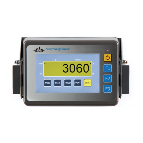
2.1 Front Panel and Keys The M3060, shown in Figure 2.1, has four keys on the front panel and a full color display with touch sensitive screen. The touch sensitive buttons on the bottom of the display work the same as traditional hard keys. -
Page 12: Display Symbols, Icons And Messages
2 Introduction to the M3060 Reference Description TARE Press TARE to tare the weight on the scale for net weighing. Press G/N to toggle between gross and net weighing modes. Press HOLD to hold a displayed weight. The weight is retained in memory HOLD in case the indicator is turned off. -
Page 13: Rear Panel Of The M3060
Gross or Net the arrow pointing to Gross or Net. 2.3 Rear Panel of the M3060 The M3060 connectors are shown as they appear on the back of the indicator in Figure and individually for greater detail following. Reference Description... -
Page 14: Chapter 3 Installation
3 Installation Installation The M3060 is designed for use in multiple situations and there are many correct ways to install and mount the indicator. Use the steps and images below to help you as you move through the steps to connect the cables. - Page 15 Figure 3.2 Bases Separated from Ball Arm Mount one of the bases to the designated location. Align the holes in the M3060 bracket with the holes on the other base. Using the hardware included with the kit, attach the bracket to the base.
- Page 16 Figure 3.4 Mounting Assembly to Location Adjust the angle of the indicator so that it is easy to use and view. Tighten the ball arm to keep the whole assembly in place. Proceed to Routing the Scale Interface Cable. M3060 User Instructions...
-
Page 17: Mounting With Desktop Mount
Clean and inspect the area where the indicator will be installed. Attach the four rubber feet to the bottom of the indicator, if necessary. Screw or bolt the mounting bracket to the location using the four holes in the mounting bracket M3060 User Instructions... -
Page 18: Routing The Scale Interface Cable
3 Installation Attach the desktop mounting bracket to the M3060. Figure 3.6 Mounting Bracket to Indicator Adjust the indicator to the desired angle. Tighten the bracket knobs finger-tight. Figure 3.7 Tighten Knobs Proceed to Routing the Scale Interface Cable. 3.3 Routing the Scale Interface Cable The scale interface cable is the cable that runs from the junction box (j-box) to the indicator. -
Page 19: Power Connections - Battery
50474-0042 30 ft. power cable Figure 3.9 Power Connector, Battery Cable Disconnect the negative wire from the battery terminal before performing any electrical work. Loosely attach the connector end of the power cable to the M3060 indicator. M3060 User Instructions... - Page 20 Crimp the ring terminals (item 1) onto the wires as shown in figure 3.11. Using a heat gun, shrink all three pieces of heat shrink tubing in place. M3060 User Instructions...
- Page 21 Tighten the AMP connector on the underside of the indicator. See figure 3.9. Reconnect battery power. Press and hold the On/Off key on the M3060 until the red light above the key comes on. Check that the instrument powers on.
-
Page 22: Power Connections - Ac
Tighten the AMP connector on the underside of the indicator. Plug the AC adapter in to the outlet. Press and hold the On/Off key on the M3060 until the red light above the key comes on. Check that the indicator powers on. -
Page 23: Additional Connectors
Tighten the connector at the indicator. Reconnect power to the indicator and device. Press and hold the On/Off button on the M3060 until the red light comes on and the indicator powers on. For a list of optional cables and serial devices, see Additional Hardware on page 3.6.1 Additional Connectors... -
Page 24: Chapter 4 Operation
Operation This section covers using the standard application. 4.1 Powering the M3060 To turn the indicator on, press and hold the ON/OFF key, shown below, until the red light above the key illuminates. Figure 4.1 On/Off Key The following screen appears Figure 4.2 Logo Screen shown during startup... -
Page 25: Simple Weighing
Place material on the scale to be tared. The gross weight of the material appears. Press the TARE key on the screen. The weight returns to zero and the arrow points to the Net annunciator. Figure 4.5 Net Weight at Zero M3060 User Instructions... -
Page 26: Loading Or Unloading Consecutive Net Amounts
Gross. Press the ZERO key on the screen to zero the system. Place the initial amount of material on the scale. The gross weight of the material appears. Press the TARE key on the screen. M3060 User Instructions... -
Page 27: Using Hold
4.5 Using HOLD Use the HOLD feature to prevent a zero shift from occurring on a portable scale system such a s a mixer, weigh cart, grain cart, etc. or to maintain weight when the indicator is powered off. M3060 User Instructions... -
Page 28: Maintain Weight For Mobile Systems
HOLD works in both gross and net weighing. If you were using net weighing before turning the indicator off, when you turn it back on, the indicator will return to net weighing. The same is true for gross weighing. M3060 User Instructions... -
Page 29: Printing
Printing 4.6 Printing If you have connected a printer to your M3060, you can quickly print the gross, tare and net weights with time and date by pressing the PRINT key on the screen when the weight is stable. Figure 4.10 Sample Printout The scale must return to zero and the weight must be stable before you can print again. -
Page 30: Chapter 5 Setup And Diagnostics
This chapter covers the setup and diagnostics of the M3060. 5.1 Entering Alphanumeric Values The alphanumeric entry screen appears often during setup and use of the M3060. This screen mimics a cell phone pad for numeric or text entry. Follow these steps to enter an alpha, numeric or alphanumeric value: Figure 5.1 Alphanumeric entry screen (Password in this example) - Page 31 Press the Clear key to erase the last character entry or all highlighted characters. Press the Adv key to advance the cursor to the next position. When you are finished entering characters, press Enter to save the data. M3060 User Instructions...
-
Page 32: Menus And Modules
5 Setup and Diagnostics 5.2 Menus and Modules The M3060 indicator has 2 password protected menus that give access to specific modules or areas of indicator function MENU NAME PASSWORD User Management Menu Diagnostic Management Menu A module remains the same no matter which menu you access it from, except for minor exceptions noted in the overview and full descriptions. -
Page 33: Accessing The Menus
Figure 5.5 Password entry screen Key in the password for the menu you want to access and press Enter. Depending on the password you entered, one of the following screens appears. Figure 5.6 User Management (left) and Diagnostics Management (right) M3060 User Instructions... -
Page 34: User Settings Module
5.5.1 To set the time With the Date And Time entry screen showing, press the hour to highlight it. Press the left arrow to decrease the value or the right arrow to increase the value. M3060 User Instructions... -
Page 35: To Set The Date
An X in the Display on Weight Screen box means the time and date will appear on the operator mode screen. Press the box to remove the X if you don’t want time and date shown. Press Enter to accept the date and return to the previous screen. M3060 User Instructions... -
Page 36: Set Speaker Volume
If using your scale for Legal-for-Trade applications (buying and / or selling based on weight), please check with your local weights and measures authority to learn what the requirements are. For applications where you are not buying or selling based on weight, you may not need this information M3060 User Instructions... -
Page 37: About M3060 Module
About M3060 Module About M3060 Module The About M3060 module shows you the revision and part number of the firmware. It is available when you enter either of the passwords. Select the About M3060 module and you will see a screen that shows you the... -
Page 38: Diagnostics Manager Module
Key in password 911 and press Enter. The following screen appears. Figure 5.14 Diagnostic Management Screen Select DIAGNOSTICS MANAGER and the screen below appears. Figure 5.15 DIAGNOSTICS MANAGER screens Each item is explained on the following pages. M3060 User Instructions... -
Page 39: Communications
Perform the Loop Back Test by placing a jumper between Pins 2 and 3 of the COM port being tested. When connected, the NO LOOP should change to LOOP. If this does not happen, contact your service representative. COM Port Description +5 V +8 V Figure 5.17 Sample COM Port M3060 User Instructions... -
Page 40: View Ethernet Settings
If you are using the Standard Application, by default, your indicator is not set up to use ethernet. If you need this feature, please contact your local Avery Weigh-Tronix representative. Select Ethernet Diagnostics from the COMMUNICATIONS screen to view ethernet settings and errors. -
Page 41: View Wifi Data
(WiFi). If you are using the Standard Application, by default, your indicator is not set up to use WiFi. If you need this feature, please contact your local Avery Weigh-Tronix representative. If your indicator is configured to use WiFi communication, Select WiFi Diagnostics from the COMMUNICATIONS screen to view WiFi settings and errors. -
Page 42: Test Keypad
Figure 5.21 Keypad Diagnostics Screen 2 Press Exit to return to the previous screen. 5.14 Test Touchscreen To test the touchscreen, select Touchscreen from the DIAGNOSTICS MANAGER screen. The screen in Figure 5.22 appears. Figure 5.22 Touchscreen Diagnostics screen M3060 User Instructions... -
Page 43: View Raw Counts
(Active or Inactive) of the available inputs and outputs. Toggle the output on or off to change the status. Additional trips using and optional cable are available from your local Avery Weigh-Tronix representative. 5.17 Seal Switch This indicator has a Category 3 audit trail. For those states that require a physical seal, this item allows you to view the status of the seal switch;... -
Page 44: Over/Under Load Viewer
Select Over/Under Load Viewer from the DIAGNOSTICS MANAGER screen and you will see a screen like this example: Figure 5.25 Overload / Underload counter The default overload trigger is 105% of capacity. The default underload trigger is 20% of capacity. M3060 User Instructions... -
Page 45: Menu Maps
Refer to the following menu maps to help you through the available menus. Click on the blue text to jump to the section where that topic is covered. Additional password- protected menus are available in the service manual. Figure 5.26 Menu Map Password 111 Figure 5.27 Menu Map Password 911 M3060 User Instructions... -
Page 46: Chapter 6 Extras
2K x 0.2 2K x 0.5 Custom Setting 20K x 1 20K x 2 20K x 5 200K x 10 200K x 20 200K x 50 Custom Setting 200K x 100 200K x 200 200K x 500 3rd Digit M3060 User Instructions... - Page 47 Press and hold the F1 key until the screen changes. Key in password 0603. Press Enter two times. Select Configuration Number: Key in the five digit configuration number. Press Enter. Press Esc three times. Press Yes when prompted to save. M3060 User Instructions...
-
Page 48: Additional Hardware
6 Extras 6.2 Additional Hardware The following items are available from your Avery Weigh-Tronix representative. To PC To M3060 Part Number Description To XLR Remote 53793-0018 Serial Cable; Transfer data to and from PC PC to M3060 AWT25-500477 XLR Cable... - Page 50 Avery Weigh-Tronix USA 1000 Armstrong Dr. Fairmont MN 56031 USA Tel:507-238-4461 Fax:507-238-4195 Email: usinfo@awtxglobal.com www.agscales.com Avery Weigh-Tronix UK Foundry Lane, Smethwick, West Midlands, England B66 2LP Tel:+44 (0) 8453 66 77 88 Fax: +44 (0)121 224 8183 Email: info@awtxglobal.com www.averyweigh-tronix.com...
Need help?
Do you have a question about the M3060 and is the answer not in the manual?
Questions and answers