Table of Contents
Advertisement
Advertisement
Table of Contents

Related Manuals for Avery Weigh-Tronix WPI-135


Summary of Contents for Avery Weigh-Tronix WPI-135
- Page 1 WPI-135 Indicator Service Manual...
-
Page 3: Table Of Contents
Table of Contents Table of Contents ...................... 3 Specifications ......................4 Introduction ....................... 5 About This Manual ....................5 Front Panel Keys and Functions ................5 Hard Keys ......................6 Soft Keys ......................7 Menu Structure ......................7 Instructions for Accessing the Menus ..............8 User Menu ......................... -
Page 4: Specifications
Specifications Power Input 85-265 VAC, 50/60Hz, single phase Excitation 10 Volts DC or 10 volts AC square wave capable of driving up to thirty-two 350-ohm weight sensors. Indicator is also capable of driving three Quartzell transducers Operational Keys Zero, Tare, Print, Units, Select, Enter, Escape, Clear, 0-9, Decimal Point and Five Soft Keys labeled per selected operational routine. -
Page 5: Introduction
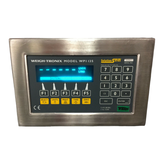
Figure 1 WPI-135 Front Panel The keys on the front panel of the WPI-135 are of two types, hard keys and soft keys. Hard keys are labeled directly and soft key labels appear on the display. Soft keys function differently at different times so their labels change... -
Page 6: Hard Keys
Below are brief descriptions for each of the hard key functions: Hard Keys Repeatedly press the SELECT key to scroll through the available weight reading displays. (Examples - gross, net, tare, minimum, maximum, etc.) Press the UNITS key to scroll through the available units of measure By default the print format #0 sends:... -
Page 7: Soft Keys
Menu Structure There are several menus you use to setup or service the WPI-135. You access the menus described below through the front panel. Each menu is briefly described here. For in depth information about a menu, go to that menu's section in this manual. -
Page 8: Instructions For Accessing The Menus
By press- Accessing the Menus ing the appropriate soft key and following text prompts on the display, you can set up your WPI-135 to suit your needs. Following are the instructions you need to access the menus of the WPI- 135. -
Page 9: User-Clock
The User menu is not affected if the indicator is sealed or unsealed. The values under SELECT in the flowchart to the right are not saved after a power down and power up. Figure 4 Soft key flowchart for User menu Press the CLOCK soft key to access the time and date setting function. -
Page 10: User-Select
You cannot select a scale number unless it has been activated in the SimPoser program and downloaded to the WPI-135, or enabled in the Config menu. User If you press the TARE soft key the display will show the current tare value for the active scale. -
Page 11: User-Set
If you press the UNIT soft key the display will ask you to key in a number (0- User 6) which represents the value you want to be active. Below are the seven —SELECT units to choose from and the corresponding number you need to key in for —UNIT this function: 0- lb... -
Page 12: User-View
Press the VIEW soft key to access the User-VIEW soft key group: User VERS Press this key to see WPI-135 firmware part number, revision —VIEW information (time, date and revision letter), serial number, Xilinx part number and revision, and information about a downloaded SimPoser program (license number, company name, version number, name of file and time and date downloaded. - Page 13 • SimPoser license number and license holder of the person that saved the file • SimPoser license number and license holder of the person that down- loaded the file • Version of the SimPoser that created the file • File name •...
-
Page 14: Configuration Menu
You must key in the password screen shown in Figure 5. within 5 seconds of accessing the password screen or the WPI-135 returns to normal operation. Figure 5 Configuration menu display Figure 6 is a flowchart showing what soft keys or choices appear as you... - Page 15 Figure 6 Soft key flowchart for Configure menu...
-
Page 16: Configuration-Menu1
Press the MENU1 soft key to access the following soft key group: Configuration —MENU 1 #SCL Press this key to set number of active scales, UNITS Use this key to enable/disable units of measure. KEYS Use this key to enable or disable front panel keys SERIAL Use this key to set port #, baud rate, parity, databits, hand- shake, mode, and EOM character. - Page 17 If you press the KEYS soft key, follow these instructions: Configuration —MENU1 1. The display asks if you want to —KEYS enable the SELECT key and shows you the current state ( ON or OFF ). If the condition is as you want it, simply press the ENTER key.
- Page 18 4 = Computer 1 = Keyboard 3 = Multidrop BASIC Control - Control of the serial port is through the BASIC program executing in the WPI-135. Keyboard - Control of the serial port is through an attached key- board. Disabled - The serial port is not in use for this configuration.
-
Page 19: Configuration-Menu2
Press this key to configure the display update rate in updates per second. ROC stands for Rate of Change. Press this key to set up your WPI-135 Indicator to calculate Rate of Change for flow rate, or weight/time, applications. RZ/TO Press this key to configure Print Return to Zero (RZ), Accumula- tor RZ, Accumulator Timeout, Print Timeout and Zero Timeout. - Page 20 Harmonizer. —FILTER The A-D weight conversion happens 60 times per second in the WPI-135. AVG is the number of conversions you want to average. For example, if you pick 30, the unit will average the weight values from the last 30 conversions or ½...
- Page 21 The number of samples over which the rate of change of weight is deter- mined. The WPI-135 converts weight from A to D at 60 times per second. If ROC Samples is set to 60, the WPI-135 is determining the rate of weight...
- Page 22 ROC Mult The ROC Multiplier allows you to enter a conversion factor to translate weight to some other unit of measure, such as gallons or some other weight unit based upon the calibration unit of measure. ROC Examples: If pounds is your calibration unit, pick a sample value of 60 and a multiplier of 1.
- Page 23 Press the MENU3 soft key to access the following soft key group: Configure —MENU3 SETPT Press this key to enable or disable viewing of setpoint state in the right corner of the weight display. FMTPT Press this key to configure a port to use for each print format. DMODE Press this key to pick a power-up display mode from those available in Appendix 1: Display Samples .
- Page 24 3. Press ENTER to keep the displayed volume or press the soft key for: OFF, LOW, MED or HIGH. Press ENTER after making your choice. . . The default print format screen is displayed. 4. Press ENTER to keep the displayed default print format or type in a new format number and press ENTER to accept it.
-
Page 25: Configuration-Menu4
The only soft key in MENU4 is the CLRPRG key. Press this key only if you Configure want to clear the BASIC program from the indicator memory. —MENU4 WARNING: Do this only if you are sure it is absolutely necessary! Press the ESC key then the EXIT soft key to exit the Configure menu. -
Page 26: Calibrate-Setup
Figure 8 Soft key flowchart for Calibration menu Press the SETUP soft key to access the following soft key group: Calibrate CAPAC Press this key to enter the capacity of the scale and the division —SETUP size. OPTION Press this key to enable or disable multi-interval use. Following are detailed instructions for setting these parameters. -
Page 27: Calibrate-Cal
Press the OPTION soft key to enable or disable the multi-interval option. If Calibrate you enable the multi-interval option, the division size you choose under —SETUP CAPAC applies to weight on the scale from 0 to ½ capacity. For weight on —OPTION the scale from ½... - Page 28 Use the SPEC soft key to access three new softkeys. These soft keys are Calibrate listed below. —CAL —SPEC TZERO This stands for temporary zero. This calibration procedure is useful when a scale has weight on it that is impractical to remove, such as a hopper or bin which is partially full of mate- rial.
- Page 29 Calibrate Press the KEY IN soft key if you want to set up a new indicator to replace —CAL another indicator and keep the original indicator's calibration settings. To do —SPEC this you must have recorded the zero counts or mV/V values of the original —KEY IN indicator in order to transfer that information to the new indicator.
-
Page 30: Calibrate-Info
Calibrate If you press the R-CAL soft key, you can perform a reverse calibration. In —CAL other words, you start with a loaded scale, remove all the weight from the —SPEC scale for spanning, then get your zero reading. This may require a container —R-CAL on a separate scale into which you discharge the material. -
Page 31: Calibrate-Exit
If you press the VERS soft key, you can see all the following information on Calibrate consecutive screens as you press any key to continue. The SimPoser —INFO information will be available only if a file has been downloaded to the indica- —VERS tor. -
Page 32: Test Menu
Test Menu There is one more menu that you can access for testing purposes. The flowchart of soft keys in the menu are shown in Figure 9. Figure 9 Flowchart of soft keys in the Test menu Hold the ESCAPE key for 5 seconds then key in 911 at the prompt. These softkeys appear: KEYPAD This test lets you check each front panel key for proper opera-... - Page 33 • Software version of the cell (vD.A in this example) For analog scales you are shown: • a raw count value and its equivalent mV/V value. (These values should be positive and increase as weight is applied. SERIAL Use this to test your ports. Select Port #1 through 4 then short the TX and RX on the selected port.
-
Page 34: Disassembly And Reassembly
Disassembly and Reassembly Following are the steps for disassembly and reassembly of the WPI-135 for service purposes. 1. Disconnect the WPI-135 from power and all peripheral equipment. 2. Remove the 14 acorn nuts holding the rear panel to the case. See Figure 10. - Page 35 3. If you need to remove the power supply board from the inside of the back cover, begin by disconnecting the power supply wires and the wires leading to the main board. Remove the eight screws holding the pc board as shown in Figure 12. Figure 12 Power supply board 4.
- Page 36 5. There is a display pc board and a display module attached to the backer plate. If you need to remove the display board, disconnect the cables and remove the three standoffs and two nuts shown in Figure 14 Figure 14 Display board 6.
-
Page 37: Appendix 1: Display Samples
Appendix 1: Display Samples Bar graph below shown at 50% Bar graph below shown at 100% Checkweigher shown in underload condition below. Checkweigher shown in overload condition below. Checkweigher shown in accept condition below. - Page 39 The following are multi-scale displays. If all the lines are not used for scales, they are available for Basic text. #34, 35, 40 and 41 are small basic text. #36, 37, 42 and 43 are large basic text.
-
Page 40: Appendix 2: Tips On Using Harmonizer
Appendix 2: Tips on Using Harmonizer To find the best settings for your filter needs, follow the steps listed below. 1. What to Do: Determine the amount of positive and negative force exerted by the vibration on the scale. How to Do It: Set Threshld to 0.0, Constant to OFF, and Samples to Average to 1.0 A-Ds. -
Page 42: Parts List
Neoprene Tubing, ¼”ID x 1/16” wall (used w/ item 46) 45089-0017 4” long Display Module (VFD) 46557-0026 Foam Tape, 2-side sticky, ½”w x 1”L (used w/ item 50) 1045-05982 Dessicant bag 1088-12126 Corrosion Vapor Emitter 48680-0014 Standard WPI-135 E-Prom (U17) 52957-0012 Standard WPI-135 E-Prom (U18) 52957-0020... -
Page 44: Display/Keypad Interface Board
WPI-135 INDICATOR DISPLAY/KEYPAD INTERFACE BOARD P/N 51631-0018 WPI-135 INDICATOR KEYPAD SCHEMATIC P/N 52937-0017... -
Page 47: Main Pc Board
WPI-135 POWER SUPPLY / MAIN PC BOARD TERMINAL PIN-OUT CHARTS POWER SUPPLY BD POWER SUPPLY BD TB30-pin no. SSCU NOTES SERIAL CLOCK (do not ground) TB25 - pin no. PC-KEYBOARD NOTES SERIAL DATA (do not ground) CLOCK (do not ground) - Page 48 TERMINAL PIN-OUT CHARTS (CONTINUED) POWER SUPPLY BD TB28-A pin no. SIGNAL COMM #3 NOTES TRANSMIT RS-232 DATA OUT (do not ground) RECEIVE RS-232 DATA IN (do not ground) RS-232 hardware handshaking out (do not ground) RS-232 Hardware handshaking in (do not ground) GROUND RS-232, *TTL, KB (+) 5.0 VDC...
- Page 50 (This page intentionally blank)
- Page 51 TERMINAL PIN-OUT CHARTS (CONTINUED)
- Page 52 WPI-135 ) J-BOX ASSEMBLY (2 through 5 SCALES P/N 47404: -0011 -OO29 -0037 (2-SCALES), (3-SCALES), (4-SCALES), -0045 (5-SCALES) .
- Page 54 (This page left intentionally blank)
- Page 55 SOLID STATE CONTROL UNIT (SSCU-8) (OPTIONAL) PARTS ASSEMBLY ITEM DESCRIPTION W-T P/N Strain Relief 22380-0053 Strain Relief 15257-0024 Cable , (SSCU-To-WPI-135) 47388-0011 Enclosure (Steel, Painted) 47665-0015 Enclosure (Stainless) 47665-0023 Remote Exp. Control I/O Pc Bd 47183-0018 Lock Nut (Self Sealing) 22381-0011...
- Page 56 WPI-135 INDICATOR REMOTE EXPANDED CONTROL: I/O BOARD (OPTIONAL) P/N 47183-0018 Table 1: Table 2: Setpoints 33 thru 40 Setpoints 41 thru 48 (1)ON (2)ON (3)OFF (1)OFF (2)ON (3)OFF SETP0INT # TB # PIN # SETP0INT # TB # PIN #...
- Page 57 WPI-135 INDICATOR EXTERNAL (16) I/O CUTOFF EXPANSION BOARD (OPTIONAL) P/N 49853-0013...
- Page 58 (This page left intentionally blank)
- Page 59 Setpoint Operation If setpoints 1 thru 4 are programmed in SimPoser as inputs, the physical location for these will always be on the power supply TB31. The setpoint location for setpoints 1 thru 4 on the option card(s) will then be invalid, and do not function.
- Page 60 OPTO-22 CONTROL INTERFACE DEVICES Specifications The OPTO-22 Generation 4 I/O modules can be used on the power supply board (max. 4) or on the optional Re- mote Expanded Control Interface Boards (max. 64). OPTO-22 I/O Type External circuit External Turn on Turn off I/O operating AC or DC...
- Page 61 SSCU-8 Caution! The Solid State Control Unit 8 (SSCU-8) option boards require that the total cable length from the indicator to the last SSCU-8 box/card be two meters (approx. six feet) maximum. Noise prob- lems and intermittent communications with the SSCU-8 card will occur if this guideline is not followed.
- Page 62 (This page left intentionally blank)
- Page 63 (This page left intentionally blank)
- Page 64 WPI-135 INDICATOR-TO-PC KEYBOARD CABLE CONNECTIONS...
- Page 65 WI-135 INDICATOR REMOTE TTL KEYBOARD OPTION EYBOARD SPECIFICATIONS ENVIRONMENTAL: 32°f to 130°f (0°c to 55°c). COMMUNICATION OUTPUT: 1 start bit , 8 data bits , 1 stop bit, , selectable baud rates, TTL Asynchronous Serial. WEIGHT: 2 lb/.9 kg nominal . BAUD STANDKEY BAUD...
- Page 66 WPI-135 INDICATOR-TO-TTL KEYBOARD CABLE CONNECTIONS...
- Page 67 WPI-135 INDICATOR TTL KEYBOARD OUTLINE DRAWINGS...
- Page 68 WPI-135 ENCLOSURE ( W/ STAND) OUTLINE DRAWING...
- Page 69 (This page left intentionally blank)
- Page 70 WPI-135 INDICATOR NETWORK INTERFACE BOARD (OPTIONAL) P/N 53021-0012 Note: For more information about configuring and using the Network Interface Option boards, refer to the WPI-135 Network Installation Guide, P/N 29762-0015.
- Page 71 ModBus /TCP Ethernet NETWORK INTERFACE MODULE PC BOARD (OPTIONAL) ModBus+ NETWORK INTERFACE MODULE PC BOARD (OPTIONAL...
- Page 72 ProfiBus-DP NETWORK INTERFACE MODULE PC BOARD (optional) DeviceNet NETWORK INTERFACE MODULE PC BOARD (OPTIONAL)
- Page 73 InterBus S NETWORK INTERFACE MODULE PC BOARD (OPTIONAL) Control Net NETWORK INTERFACE MODULE PC BOARD (OPTIONAL)
- Page 74 (This page left intentionally blank)
- Page 75 Weigh-Tronix 1000 Armstrong Dr. Fairmont, MN 56031 USA Telephone: 507-238-4461 Facsimile: 507-238-4195 e-mail: industrial@weigh-tronix.com www.wtxweb.com Weigh-Tronix Canada, ULC 217 Brunswick Blvd. Pointe Claire, QC H9R 4R7 Canada Telephone: 514-695-0380 Facsimile: 514-695-6820 Weighing Products & Systems Weigh Bar ® is a registered trademark of Weigh-Tronix Inc. 09/07/00 135SERV.P65 PN 29750-0019e3 Printed in USA...
Need help?
Do you have a question about the WPI-135 and is the answer not in the manual?
Questions and answers