
Related Manuals for Avery Weigh-Tronix E1010


Summary of Contents for Avery Weigh-Tronix E1010
- Page 1 Model E1010 Indicator E1010 Service Manual ENGLISH AWT35-500132 Issue B April 23, 2007 *AWT35-500132*...
- Page 2 SOCKET-OUTLET IS LOCATED/INSTALLED NEAR THE EQUIPMENT AND IS EASILY ACCESSIBLE. ATTENTION: LE CORDON D’ALIMENTATION EST UTILISÉ COMME INTERRUPTEUR GÉNÉRAL. LA PRISE DE COURANT DOIT ÊTRE SITUÉE OU INSTALLÉE À PROXIMITÉ DE L’ÉQUIPEMENT ET ÊTRE FACILE D’ACCÉS”. E1010_rev2006_s.P65 Model E1010 Indicator Service Manual...
-
Page 3: Table Of Contents
Appendix 1: Complete Menus ....................... 54 Service Menu ......................... 54 Supervisor Menu ........................55 User Menu ..........................55 Appendix 2: Connections and Communications ................56 Common Serial Port Connections ..................56 External Inputs / Cutoffs (Trips) Connector ................56 Technical Illustrations ........................57 Model E1010 Indicator Service Manual... -
Page 4: Specifications
Time and date / RAM Class III/IIIL:10,000 divisions • Battery backed up real time clock and RAM • OIML Cert. No. R76/1992-GB1-04.09 Class III: 10,000 divisions • Canadian Weights and Measures pending • UL/CUL • CE marked Model E1010 Indicator Service Manual... -
Page 5: Introduction
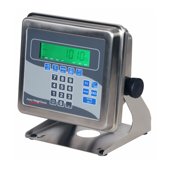
Front Panel The front panel, shown in Figure 1, consists of the keys and display. The Model E1010 is battery powered. The unit can be run on AC power if the battery is drained or absent. -
Page 6: Keys
The application name is briefly displayed when key is released. Press the ESC key to escape a function or return to normal operation mode. Press and hold to access the password display for the menu structure. Press the ENTER key to accept displayed choices. Model E1010 Indicator Service Manual... -
Page 7: Battery Information
(single loadcell). The AC adapter/ replaced by an incorrect type. charger will charge the battery as it powers the indicator. Dispose of used batteries according to the manufacturer’s instructions. Model E1010 Indicator Service Manual... -
Page 8: Error Messages
If you are in the counting sample mode menus, this means the piece weight is too small, make the sample size larger. Model E1010 Indicator Service Manual... -
Page 9: Accessing The Menus
Menu Structure There are several menus you use to setup or service the Model E1010. You access the menus through the front panel. Each menu is briefly described here. For in depth information about a menu, go to that menu's section in this manual. -
Page 10: User Menu
All the display elements flash. 8. Press the SELECT key to stop the test. . . DISP is displayed. 9. Press the UNITS key. . . BUTTON is displayed. This is the button test item. Model E1010 Indicator Service Manual... - Page 11 14. Press the SELECT key to exit the serial test. SERIAL is displayed. Remove the jumper from the TX and RX lines of the DB-9 serial connector. 15. Press the SELECT key. . . TEST is displayed. Model E1010 Indicator Service Manual...
- Page 12 Press the PRINT key to see the number of times the indicator has been calibrated. This number is displayed temporarily and then CAL is displayed. 19. Press ESC twice to return to normal operation mode. Model E1010 Indicator Service Manual...
-
Page 13: Service Menu
4. Press the ENTER key to perform the zero procedure. . . BUSY is briefly displayed then the live weight which should be 0. 5. Press the ENTER key to save and return to the ZERO menu item. . . ZERO is displayed. Model E1010 Indicator Service Manual... - Page 14 5. Place the test weight for this calibration on the scale and press ENTER. . . Busy is briefly displayed and then 2. 6. Press the UNITS key to move to the next calibration point. . . 3 is displayed. Model E1010 Indicator Service Manual...
- Page 15 2. Press the PRINT key. . . The live weight is displayed. 3. Press the ENTER key to return to DISP. 4. Press the SELECT key. . . CAL is displayed. This completes the CAL section of the Service menu. Model E1010 Indicator Service Manual...
-
Page 16: Scale Submenu
CAP. is displayed. Use this item to set the capacity for the scale. 4. Press the PRINT key. . . The current capacity value is shown. 5. Press ENTER to accept this value or key in a new capacity and press ENTER. . . CAP. is displayed. Model E1010 Indicator Service Manual... - Page 17 UNITS is displayed. 2. Press the PRINT key. . . LB is displayed. LB, 1000G or CUST are your choices for units of measure. These stand for pounds, kilograms, or a custom unit of measure. Model E1010 Indicator Service Manual...
- Page 18 The current division size is displayed. If a weight changes less than this number of divisions in one second, the motion annunciator turns off and the weight is considered stable. You choices are 0, 0.25, 0.5, 0.7, 1, 3, 5, and 10. Model E1010 Indicator Service Manual...
- Page 19 PRINT key. . . ON or OFF is displayed. 4. Toggle between the choices using the TARE or UNITS key. When your choice is displayed press the ENTER key then press the SELECT key. . TARE is displayed. Model E1010 Indicator Service Manual...
- Page 20 2. Press the PRINT key. . . The current setting is displayed. 3. Toggle between the choices, DEC or COMMA, by using the UNITS or TARE key and press the ENTER key to accept the choice. . . D.POINT is displayed. Model E1010 Indicator Service Manual...
- Page 21 2. Press the PRINT key. . . The current setting is displayed. 3. Key in a new value and press ENTER to accept the value Press the ENTER key to accept the displayed choice. . . G-BAND is displayed. Model E1010 Indicator Service Manual...
- Page 22 SERIAL is displayed. This completes the SCALE portion of the Service menu. To exit to normal weighing mode, press the ESC key Press the SELECT key and continue to the APP submenu covered in the next section. Model E1010 Indicator Service Manual...
-
Page 23: App Submenu
5. Toggle between the choices by using the UNITS key or TARE key and press the ENTER key to accept the displayed choice. . INIT-NA or INIT-EU is displayed briefly then SITE is displayed. INIT stands for initializing the defaults. Model E1010 Indicator Service Manual... - Page 24 014 and press the ENTER key. To print the 0, 1, 3, and 10 for- mats, key in 01310 and press the ENTER key… Always enter format numbers in ascending order. P-FT is displayed. 9. Press the SELECT key twice… GENERAL is displayed. Model E1010 Indicator Service Manual...
- Page 25 (Peak hold application) TOP is displayed. 2. Press the PRINT key… Repeat steps 2-9 from the General (General weighing application) section to set up the Target application. 3. Press the SELECT key twice… TOP is displayed. Model E1010 Indicator Service Manual...
- Page 26 This completes the APP menu but see below for more information on using the E1010 as a remote display. “ To use an E1010 as a remote display the following configurations need to be Using an E1010 as set. a Remote Display 1.
-
Page 27: Extra Info: Print Format Editing
In The default print format for the accumulator application is shown the E1010 the maximum in a sample printout on the next page. sequence length is 128. Model E1010 Indicator Service Manual... - Page 28 Serial menu, which is explained later in this manual. Format 15 = Format 0 for the Each custom format is numbered and can have a value of 1-9. See Top mode note at left. Model E1010 Indicator Service Manual...
- Page 29 Table 1 Printable characters chart Model E1010 Indicator Service Manual...
- Page 30 Net Accumulator Gross Accumulator Print the displayed weight Weight Print the active value (‘G’ for gross, ‘N’ for net, ‘T’ for tare) Weight Date with 4 digit year Peak Hold Weight Value End of String String Model E1010 Indicator Service Manual...
-
Page 31: Serial Submenu
BAUD is displayed. Use this item to set the baud rate. Choices are from 300 to 115,200. Default is 9600. 4. Scroll the choices by using the UNITS key or TARE key and press the ENTER key to accept the displayed choice. . BAUD is displayed. Model E1010 Indicator Service Manual... - Page 32 2. Press the PRINT key. . . NONE, RTS or SOFT (Xon/Xoff) is displayed. 3. Scroll through the choices by using the UNITS key or TARE key and press the ENTER key to accept the displayed choice. . C-TROL is displayed. Model E1010 Indicator Service Manual...
- Page 33 If communication is lost between the host and the remote, the remote will display “-“, middle dashes, until a signal is acquired again. Model E1010 Indicator Service Manual...
- Page 34 2. Press the PRINT key. . . Current setting is displayed. 3. Scroll through the choices by using the UNITS key or TARE key and press the ENTER key to accept the displayed choice. . TYPE is displayed. Model E1010 Indicator Service Manual...
- Page 35 Count mode This completes the SERIAL submenu. Press the UNITS key to go to the Format 15 = Format 0 for the TEST submenu or press ZERO to return to normal weighing mode. Top mode Model E1010 Indicator Service Manual...
-
Page 36: Test Submenu
ADC is displayed. This stands for the analog to digital converter value in mV/Vs. 5. Press the PRINT key. . . The mV/V value coming into the indicator is displayed. 6. Press the SELECT. . . ADC is displayed. Model E1010 Indicator Service Manual... - Page 37 To test input 2, jumper pins 1 and 3. 2 becomes 0 until the jumper is removed. To test input 3, jumper pins 1 and 4. 3 becomes 0 until the jumper is removed. 19. Press the SELECT key. . . INPUT is displayed. Model E1010 Indicator Service Manual...
- Page 38 26. Press the SELECT key. . . TEST is displayed. This completes the TEST section of the menu. Press the ZERO key to return to normal operating mode or press the UNITS key to move to the next menu item, AUDIT. Model E1010 Indicator Service Manual...
-
Page 39: Audit Submenu
5. Press the SELECT key. . . AUDIT is displayed. This completes the AUDIT submenu. Press the UNITS key to go to the INPUT submenu or press ZERO to return to normal weighing mode. Model E1010 Indicator Service Manual... -
Page 40: Input Submenu
ENTER key to accept the displayed choice. . INPUT is displayed. This completes the INPUT submenu. Press the UNITS key to go to the OUTPUT submenu or press ZERO to return to normal weighing mode. Model E1010 Indicator Service Manual... -
Page 41: Output Submenu
ENTER key to accept the displayed choice. . . OUTPUT is displayed. 5. Press the ZERO key and the indicator returns to normal weighing mode. See the output/annunciator/TIU3 relay relationship for each application on the following page. Model E1010 Indicator Service Manual... - Page 42 Outputs are ON Outputs are OFF peak mode: Annunciators are OFF Annunciators are ON TIU3 Relays are ON TIU3 Relays are OFF This completes the Service menu. Press the ZERO key to return to normal weighing mode. Model E1010 Indicator Service Manual...
-
Page 43: Supervisor Menu
WARNING: Entering this menu and changing settings menu is 1793. may affect operation of the indicator and may require a service call to correct. Be sure you want to change set- tings before doing so. Figure 13 Supervisor menu flowchart Model E1010 Indicator Service Manual... -
Page 44: Date Submenu (Set Date)
HH XX is displayed. This stands for hour and its current value. See note at left. 5. Key in the hour in military time and press the ENTER key… nn XX is displayed. nn stands for minute and XX represents the current value. Model E1010 Indicator Service Manual... -
Page 45: Setup Submenu (Setup Menu)
Applications are enabled and disabled in a password protected menu but you do each application’s configuration under this menu item. Contact your local supplier or Avery Weigh-Tronix distributor for assistance with the password protected menu. 5. Press the PRINT key…... - Page 46 ACC. is displayed. This stands for the accumulator application. 15. Press the PRINT key… PRINT is displayed. Use this item to print out a complete report of accumulator totals. 16. Press the ENTER key … Display shows BUSY briefly then returns to PRINT. Model E1010 Indicator Service Manual...
- Page 47 25. Press the PRINT key… The current type setting is displayed. 26. Toggle between the choices by pressing the TARE or UNITS key. Press the ENTER key when your choice is displayed… TYPE is displayed. Model E1010 Indicator Service Manual...
- Page 48 ±1 division of the target weight. 5. Toggle between the choices by pressing the TARE or UNITS key. Press the ENTER key when your choice is displayed… TYPE is displayed. Model E1010 Indicator Service Manual...
- Page 49 5. Press the ENTER key… SURE? is displayed. 6. Press the ESC key to abort the save process or press the ENTER key to clear all the information… CLEAR is displayed. 7. Press the SELECT key… COUNT is displayed. Model E1010 Indicator Service Manual...
- Page 50 6. Press the ESC key to abort the save process or press the ENTER key to clear all the information… CLEAR is displayed. 7. Press the SELECT key repeatedly until SETUP is displayed. This concludes the Application section of the Supervisor menu. Model E1010 Indicator Service Manual...
-
Page 51: Test Submenu (Test Menu)
10. Press the PRINT key to perform a button test. Each key you press will be reflected on the display screen to confirm the button is functioning correctly. 11. Press the ESC key to stop the button test. BUTTON is displayed. Model E1010 Indicator Service Manual... - Page 52 Monitor the output to see that it is turning on and off. 23. Stop the test by pressing the SELECT key… OUT 1 is displayed. 24. Press the UNITS key… OUT 2 is displayed. Model E1010 Indicator Service Manual...
-
Page 53: Audit Submenu (Audit Counters)
Any motion or any key press restarts the sleep timer. 3. Press ENTER when choice is displayed… SLEEP is displayed. This completes the Sleep item and the Supervisor menu. Press ESC to save and return to normal weighing operation. Model E1010 Indicator Service Manual... -
Page 54: Appendix 1: Complete Menus
The Menu indicator is unsealed when the switch under the access cover is towards the outside edge of the indicator. It is in the sealed position If it is towards the center of the indicator. Model E1010 Indicator Service Manual... -
Page 55: Supervisor Menu
Supervisor Menu User Menu Model E1010 Indicator Service Manual... -
Page 56: Appendix 2: Connections And Communications
Out - In – In + Out + In - Out - External Inputs / Cutoffs (Trips) Connector NOTE: Cutoffs (Trips) Output = 30Vdc max or 500mA max AND total power must not exceed 180mW. Model E1010 Indicator Service Manual... -
Page 57: Technical Illustrations
MODEL E1010 SST INDICATOR Technical Drawings Parts Lists and Illustrations (This Page Intentionally Blank) - Page 58 MODEL E1010 SST INDICATOR ENCLOSURE PARTS AND ASSEMBLY (SEE PARTS LIST NEXT PAGE) NOTE TORQUE SPEC: M6 Acorn Nuts (items 12 and 28) torque in a corner-to-corner pattern, first to 26 in. lbs.[2.9 N·m], and then to 44 in. lbs. [5.0 N·m].
- Page 59 Battery Cable Assy (optional; used with item 35) Apply “Lock-Tite (red)” (item 46) to thread end opposite Front Enclosure Ass’y, E1010, (incl: keypad overlay, of the hex socket end. Using a 3mm hex wrench, front encl., display window, adhesive backing) 57720-0025 thread set screw into the knob on “...
- Page 60 MODEL E1010 SST INDICATOR DIMENSIONAL OUTLINE DRAWING Peak Print Cust TARE SELECT ZERO PRINT UNITS MODE ENTER...
- Page 61 MODEL E1010 SST INDICATOR WALL-MOUNT APPLICATION...
- Page 62 MODEL E1010 SST INDICATOR SYSTEM BLOCK DIAGRAM Weight Sensor-to-J2 (Main Bd.) Wire Color Chart +EXC +SENSE -EXC -SENSE +SIGNAL SHIELD/GND -SIGNAL AWT Wire Color GRN WHT/ORN SMA Wire Color WHT/ORN WEIGHT SENSOR-TO-J2 (MAIN BD.) WIRE COLOR CHART +EXC +SENSE -EXC...
- Page 63 MODEL E1010 SST INDICATOR KEYPAD (ref: keypad assy in parts list, item 5) & SCHEMATIC, Peak Print Cust TARE SELECT ZERO PRINT UNITS MODE ENTER...
- Page 64 MODEL E1010 SST INDICATOR MAIN BOARD ASSY Lithium 3.0 volts E1010 Main Board Serial COMM (TB7) Data Chart Pin 1 Pin 2 Pin 3 Pin 4 Pin 5 Pin 6 Pin 7 SERIAL COMM (TB7) DATA CHART (GREEN) (YELLOW) (RED)
- Page 65 MODEL E1010 SST INDICATOR I/O EXTERNAL CABLE IDENTIFICATION PIN-OUTS...
- Page 66 MODEL E1010 SST INDICATOR Warning ! Do not allow metallic materials to simultaneously contact negative and positive Battery Kit Installation, Kit P/N 57777-0019 terminals of cells and batteries. Remove insulating sleeves from battery terminals prior to connecting battery cable ass’y.
- Page 67 MODEL E1010 SST INDICATOR TRIPS INTERFACE UNIT (TIU3) (OPTIONAL) & ASSEMBLY ITEM DESCRIPTION AWT P/N Enclosure (stainless steel) AC Power Cord (USA) AC Power Cord (UK) Cover (stainless steel) Gasket 55908-0015 Relay Control PC Board Assy 56957-0013mts Neoprene Plug (1/4” dia.) Neoprene Plug (8mm dia.)
- Page 68 Pointe Claire, QC H9R 4R7 Canada Weigh Bar ® is a registered trademark Telephone: 514-695-0380 of Avery Weigh-Tronix and may be registered in certain jurisdictions. Toll free: 800-561-9461 All brands and product names used Facsimile: 514-695-6820 within this document are trademarks www.weigh-tronix.ca...
Need help?
Do you have a question about the E1010 and is the answer not in the manual?
Questions and answers