
Related Manuals for Avery Weigh-Tronix E1070


Summary of Contents for Avery Weigh-Tronix E1070
- Page 1 Model E1070 Indicator Service Manual NORTH AMERICA AWT35-500106 Issue AF March 2010...
- Page 2 Full acknowledgment of the source must be given. Avery Weigh-Tronix is a registered trade mark of the Avery Weigh-Tronix, LLC. This publication was correct at the time of going to print however, Avery Weigh-Tronix, LLC reserves the right to alter without notice the specification, design, price or conditions of supply of any product or service at any time.
-
Page 3: Table Of Contents
HOUR (Set time) ..................... 111 SETUP (Setup menu) ....................111 TEST (Test menu) ....................127 AUDIT (Audit counters) menu ................131 Chapter 4 SensorComm Hardware Configuration and Calibration ........... 132 Introduction ........................132 Enable SensorComm ..................... 132 E1070 Indicator Service Manual... - Page 4 Chapter 10 Complete Menu Structures ....................149 Complete Supervisor and User Menus ................149 Complete Service Menu ....................150 Chapter 11 E1070 Technical Illustrations .................... 151 Enclosure Parts and Assembly ..................151 Enclosure Parts and Assembly ..................152 Wall Mount Application ....................153 System Block Diagram ....................
-
Page 5: Manual Revision History
Updates to SCALE menu. GTU added to print tokens. Other small changes. March 2010 Added note at top of page 50 on default print format file. Also fixed a dimension on a label on the same page. Per RFC-501164. E1070 Service Manual... - Page 6 E1070 Service Manual...
-
Page 7: Chapter 1 General Information And Warnings
Warnings mean that failure to follow specific practices and procedures may have major consequences such as injury or death. CAUTION! This is a Caution symbol. Cautions give information about procedures that, if not observed, could result in damage to equipment or corruption to and loss of data. E1070 Service Manual... -
Page 8: Installation
Permanently connected equipment must have a readily accessible disconnect device incorporated in the fixed wiring such as an isolator or circuit breaker with at least 3mm contact separation. The isolator MUST NOT be installed into the flexible power cable supplied with the unit. E1070 Service Manual... -
Page 9: Safe Handling Of Equipment With Batteries
Always turn off the machine and isolate from the power supply before starting any routine maintenance to avoid the possibility of electric shock. Make sure that it is placed securely on a flat and level surface. E1070 Service Manual... -
Page 10: Cleaning The Machine
To avoid the risk of RSI (Repetitive Strain Injury), place the machine on a surface which is ergonomically satisfactory to the user. Take frequent breaks during prolonged usage. 1.7 Sharp objects Do not use sharp objects such as screwdrivers or long fingernails to operate the keys. E1070 Service Manual... -
Page 11: Fcc And Emc Declarations Of Compliance
Classe A prescrites dans le Règlement sur le brouillage radioélectrique edicté par le ministère des Communications du Canada. European Countries WARNING: This is a Class A product. In a domestic environment, this product may cause radio interference in which the user may be required to take adequate measures. E1070 Service Manual... -
Page 12: Chapter 2 Introduction
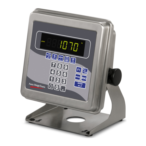
This manual covers the information you need to configure and service your Model E1070 Indicator. Front Panel The front panel, shown in Figure 2.1, consists of the keys and display. Figure 2.1 E1070 front panel 2.1.1 Keys The functions of the keys on the front panel are listed on the following pages. - Page 13 2.1 Front Panel IMPORTANT: Plug the Model E1070 into properly grounded socket-outlet of the correct voltage, installed near the equipment and easily accessible. Never use the unit without an appropriate earthground connection. Any computer based system should have a separate, grounded power circuit. We recommend one for the Model E1070.
- Page 14 Press the ESC key to escape, or abort, a function or return to normal operation mode. Press the ENTER key to accept displayed choices. Press and release the ON/OFF key to turn the unit on. Press and hold the key until the unit turns off. Use the numeric keypad to enter values. E1070 Service Manual...
-
Page 15: Annunciators
Red – A network error has occurred. Check the network settings on the indicator and PLC, and reboot the indicator. Green – The network connection has been established. Amber – The network is ready for a connection, but no connection has been established. E1070 Service Manual... -
Page 16: Error Messages
Entered value causes resolution of greater than 100,000 divisions. Linear points must be done in order from lightest weight to heaviestWhen you are in the Span menu item in the Service menu, you may see the following errors: E1070 Service Manual... - Page 17 Entered value is greater than the configured scale capacity. Entered value is less than 1% of scale capacity. Entered value causes resolution of greater than 100,000 divisions. No ADC counts OR in Overload OR All these relate to mV/V input in Underload E1070 Service Manual...
-
Page 18: Chapter 3 Using The Menus
3 Using the Menus Available Menus There are several menus you use to setup or service the Model E1070. You access the menus through the front panel. Each menu is briefly described here. For in depth information about a menu, go to that menu's section in this manual. -
Page 19: Accessing The Menus
The first item in that menu is displayed. Use the navigation keys shown in the box near each menu to move through the menu. You must begin to key in the password within 10 seconds or the display returns to normal operation mode. E1070 Service Manual... -
Page 20: User Menu
Press the PRINT key… The mV/V value coming into the indicator is displayed. This should change as weight on the scale changes. Press the ZERO key to zero the mV/V reading prior to diagnostics. Press the SELECT… Adc is displayed. E1070 Service Manual... - Page 21 CFg is displayed. This stands for the configuration audit counter. Press the PRINT key to see the number of times the configuration has been altered on this indicator. Press the SELECT or ENTER key… CFg is displayed. Calibration and configuration counters cannot be reset. E1070 Service Manual...
- Page 22 CAL is displayed. This stands for the calibration audit counter. Press the PRINT key… The number of times the indicator has been calibrated is displayed. Press ESC twice to return to normal operation mode. This completes the User menu. E1070 Service Manual...
-
Page 23: Service Menu
While in a menu, the fan graphs at the top of the display flash as a reminder. Since the whole Service menu is quite large, it has been broken up into its individual submenus. Each submenu is illustrated in this section followed by specific instructions for that submenu. E1070 Service Manual... -
Page 24: Cal Submenu For Analog Scales
Press the ESC key to abort calibration. Remove all weight from the scale and press the ENTER key… Live weight is shown. Press the ENTER key to perform the zero procedure… buSY is briefly displayed then the live weight which should be 0. E1070 Service Manual... - Page 25 Key in a weight value for this calibration point and press the ENTER key. Live weight on the scale is displayed. Place the test weight for this calibration on the scale and press ENTER. Busy is briefly displayed and then 2. E1070 Service Manual...
- Page 26 Linearization factors cannot be entered. To use this item you must have recorded the calibration factors from your previously installed E1070 indicator. Calibration factors can be viewed under CAL>INPUT or you can print them out using the CAL>PRINT menu item.
- Page 27 This completes the CAL section of the Service menu for analog scales. If you have a SensorComm system, see the section SensorComm Hardware Configuration and Calibration for calibration and configuration information. The next Service menu item, SCALE, is covered in the SCALE Submenu section. E1070 Service Manual...
-
Page 28: Scale Submenu
Follow the directions and explanations below to set up these items. Figure 3.4 Scale submenu flowchart Use the instructions in Accessing the Menus on page 19 to access the Service menu… CAL is displayed. Press the UNITS key… SCALE is displayed. E1070 Service Manual... - Page 29 All of these capacities function in conjunction with the decimal place position. For example, if you choose a division value of 5 and a decimal position of 12345.6, your division size will be .5. When your choice is displayed, press ENTER. div. is displayed. E1070 Service Manual...
- Page 30 C-Unit is displayed. This stands for calibration unit. Use this item to set the calibration unit of measure; lbs or kgs (1000 G). Press the PRINT key… Current calibration unit is displayed. Choices are Lb or 1000g. E1070 Service Manual...
- Page 31 Scroll through the choices by using the TARE or UNITS key and press the ENTER key to accept the displayed choice… div. is displayed for any choice other than CUSt. If you pick CUSt. go to step 5. If you picked any other division size, go to step 6. E1070 Service Manual...
- Page 32 ½ of the weight will be zeroed. The indicator will repeat removing ½ the weight every X seconds. X being the number of seconds you have picked. With StAbLE displayed, press the UNITS key… AZt is displayed. Press the PRINT key… div. is displayed. E1070 Service Manual...
- Page 33 TARE (Tare parameters) Use this item to set the tare function parameters; Clear tare If you enable (on) this item, the tare will be automatically cleared when the weight falls below the value set under the G-Band menu item. E1070 Service Manual...
- Page 34 Follow these steps to set the tare item: With AZt displayed, press the UNITS key… tArE is displayed. Press the PRINT key… CLEAr is displayed. Press the PRINT key… on or oFF is displayed. Use this to enable or disable the Clear tare item. E1070 Service Manual...
- Page 35 UPDATE (Display Update Rate) on page With EnAbLE displayed, press the UNITS key… Lo is displayed. This is the low threshold limit. Press the PRINT key… The numeric entry screen appears. E1070 Service Manual...
- Page 36 Current update rate is displayed. Choices are 1, 2, 5 and 10 times/ second. 10 is the default value Scroll through the choices by using the TARE or UNITS key and press the ENTER key to accept the displayed choice. . UPdAtE is displayed. E1070 Service Manual...
- Page 37 Filtering is used to counteract vibration of the scale. The A-D weight conversion happens 100 times per second in the E1070. AVG is the number of conversions you want to average. For example, if you pick 50, the unit will average the weight values from the last 50 conversions or ½...
- Page 38 Use this item to toggle between decimal point and a comma for the fraction delimiter for the display. For example, if you pick DEC the display will show 10.5. If you pick COMMA, the display will show 10,5. With FiLtEr displayed, press the UNITS key… d.Point is displayed. E1070 Service Manual...
- Page 39 Scale submenu. It also sets the Return to Zero range for Autoprint, Acccumulate, Checkweighing and Counting functions. You can enter values between 0 and 100 divisions. With O-CAP. displayed, press the UNITS key… G-bAnd is displayed. E1070 Service Manual...
- Page 40 This completes the SCALE portion of the Service menu. You can exit to normal weighing mode or continue on to the next menu item, APP. To exit, go to step 5. To continue, go to step 7. Press the ESC key. SAvE is displayed. E1070 Service Manual...
-
Page 41: App Submenu
Follow these steps to access each item in the APP menu and to understand what they do and how to set them: Use the instructions in Accessing the Menus on page 19 to access the Service menu… CAL is displayed. E1070 Service Manual... - Page 42 If you choose tcPIP 1 or SmtP 1, nEt 1 under OPTION>NETS must be set to E-nEt 1 or E-nEt 4. If you choose tcPIP 2 or SmtP 2, nEt 2 under OPTION>NETS must be set to E-nEt 1 or E-nEt 4. E1070 Service Manual...
- Page 43 P-Ft is displayed. When you key in a 1 followed by a 0, the indicator is smart enough to know this is a 10 not separate 1 and 0 formats. Always enter format numbers in ascending order. E1070 Service Manual...
- Page 44 With tArgEt displayed, press the UNITS key… Count is displayed. Press the PRINT key… Repeat steps through from the section ACC (Accumulator application) on page 42, to set up the Count application. Press the SELECT key… Count is displayed. E1070 Service Manual...
- Page 45 Indicator acts the same as in Mode 3 plus all the annunciators reflect the main display status Scroll through the choices using the TARE or UNITS key. When your choice is displayed, press the ENTER key… ModE 2 is displayed. E1070 Service Manual...
- Page 46 Press the PRINT key… The numeric entry screen appears. Use the numeric entry procedure to enter the number of divisions. Press the ENTER key to accept… div. is displayed. Press the SELECT key twice… APP. is displayed. E1070 Service Manual...
-
Page 47: Extra Info: Print Format Editing
ENTER Accepts print string and exits edit mode ON/OFF A short key press inserts a new character in front of the displayed character. Press and hold to delete the currently displayed hex character. E1070 Service Manual... - Page 48 You can overwrite the FF value and use up to the maximum string length if so desired. In the E1070 the maximum sequence length is 256. However, the last character in the print format must be FF. Be sure to add the FF character if it is removed.
- Page 49 17 Port 1 Enquire (HEX05) 18 Port 1 Broadcast 19 Port 1 RD4100 20 Port 2 Enquire (HEX05) 21 Port 2 Broadcast 22 Port 2 Remote display 123456 lb {ACT} {DSP} {UN}<CR><LF>{EOS} E1070 Service Manual...
-
Page 50: Thermal Labels Print Formats
3 Using the Menus 3.4.5 Thermal Labels Print Formats You must download the configuration file defaultNA.E1070 to load default print formats. Print Formats 1, 2 & 3 Time Date Gross Weight Tare Value Net Weight Format 1 label 1.25” Wide x 1.00” Long Format 2 label 2.25”... - Page 51 3.4 Service Menu Table 3.1 Printalbe Characters Chart E1070 Service Manual...
- Page 52 For ingredient units (lb or kg for weight based ingredients; sec for time based ingredients; cnts or gallons for pulse counter based ingredients). To be printed after the target or actual ingredient value. Piece Weight Count Current Count Value Count E1070 Service Manual...
- Page 53 Further, parameter values may be ASCII digits (i.e. range ‘0’ thru ‘9’) or DECIMAL values (i.e. range 0 thru 255). In all cases, parameters consume one byte. In the term/ token table parameters are indicated as follows: Optional, (ASCII) (,n) Optional, (Decimal) (,x) Mandatory, (ASCII) Mandatory, (Decimal) - E1070 Service Manual...
-
Page 54: Serial Submenu
Follow these steps to access each item in the SERIAL menu and to understand what they do and how to set them: Use the instructions in Accessing the Menus on page 19 to access the Service menu… CAL is displayed. Press the UNITS key repeatedly until… SEriAL is displayed. E1070 Service Manual... - Page 55 PAritY is displayed. Use this item to set parity. Press the PRINT key… nonE, Odd or EvEn is displayed. Scroll through the choices by using the TARE or UNITS key and press the ENTER key to accept the displayed choice. . PAritY is displayed. E1070 Service Manual...
- Page 56 Scroll through the choices by using the TARE or UNITS key and press the ENTER key to accept the displayed choice… If you pick: go to ENQ on page 58 b-CASt go to B-CAST on page 58 go to SMA on page 58 r-diSP go to R-diSP on page 61 E1070 Service Manual...
- Page 57 3.4 Service Menu rS485 (for port 1 only) go to RS-485 on page 62 485 Hd (for port 1 only) go to 485Hd on page 62 E1070 Service Manual...
- Page 58 Press the ENTER key to accept this format or key in a new format or formats and press the ENTER key to accept… b-CASt is displayed. With SMA displayed, press the PRINT key… The SMA protocol is selected and tYPE is displayed. E1070 Service Manual...
- Page 59 Attempts the take <xxxx.xx> as the weight for cutoff #<cutoff>. The indicator will respond with: Set a cutoff/trip weight. <LF>XT<cutoff><xxxx.xx>Set<CR> if the cutoff weight was accepted or <LF>XTFail<CR> if the cutoff weight could not be set to the value specified. Cutoff =1-3. Weight limited to scale cap. E1070 Service Manual...
- Page 60 <LF>XK<lower limit>,<upper limit><CR> values. <LF>XE<pcwt><CR>Set the piece The indicator will respond with: weight for the Counting application. <LF>XE<pcwt>Set<CR> <LF>XE<CR> Request the piece The indicator will respond with: weight for the Counting application. <LF>XE<pcwt><CR> E1070 Service Manual...
- Page 61 PFtX is displayed. The X stands for the current print format setting. Press the ENTER key to accept this format or key in a new format or formats and press the ENTER key to accept. Otherwise: r-diSP is displayed. E1070 Service Manual...
- Page 62 4 wire RS485 to 2 wire RS485 to A or + to B or - Jumper TXA to RXA and TXB to RXB. The indicator will adjust for the serial loop back when RS485 Half duplex is selected. E1070 Service Manual...
- Page 63 Toggle between the choices by using the TARE or UNITS key and press the ENTER key to accept the displayed choice… LEAd-0 is displayed. Press the SELECT key… Port 1 or 2 is displayed. Repeatedly press the UNITS key until… String is displayed. E1070 Service Manual...
- Page 64 Press the UNITS key to go to the TEST submenu press ESC to return to normal operation mode… If you press ESC, SAvE is displayed. Press ENTER to save the changes or the ESC key to abort the save process and return to normal operating mode. E1070 Service Manual...
-
Page 65: Test Submenu
The software revision level is displayed. Press SELECT key to return to About. ADC (Analog scale test) With About displayed, press the UNITS key… Adc is displayed. This stands for the analog to digital converter value in mV/Vs. E1070 Service Manual... - Page 66 PRINT key, the display should show PASS. If there is a problem the display will show FAIL. Repeat this for Port 2. Press SELECT key to return to the SERIAL item… SEriAL is displayed. E1070 Service Manual...
-
Page 67: Option Is Displayed
2 is displayed. Repeat steps for outputs 2 and 3… Press the SELECT key… outPut is displayed. OPTION (Option tests) With outPut displayed, press the UNITS key… oPtion is displayed. Under this item you will find the following: E1070 Service Manual... - Page 68 Scroll through the available weight sensor numbers by pressing the TARE or UNITS key. Press the ENTER key when the sensor you want to test is displayed… mV/V output of the selected sensor is displayed. Apply weight to the scale to verify the mV/V level changes. E1070 Service Manual...
- Page 69 UNITS key to go to the AUDIT submenu To return to normal weighing mode, press ESC. If you press ESC you will be prompted to save any changes made. Press ESC to abort any changes or press ENTER to save changes. E1070 Service Manual...
-
Page 70: Audit Submenu
CFg is displayed. This stands for the Configuration audit counter. Use this item to see how many times this indicator has been configured. Press the PRINT key… A number is displayed. This is the number of times this indicator has been configured. Press SELECT… CFg is displayed. E1070 Service Manual... -
Page 71: Input Submenu
TARE or UNITS key. When you access each input, by pressing the PRINT key, you get to choose from this list of input types: nonE Input does nothing ZEro Input zeroes the scale tArE Input tares the scale E1070 Service Manual... -
Page 72: Output Submenu
Follow these steps to access and configure the outputs: Use the instructions in Accessing the Menus on page 19 to access the Service menu… CAL is displayed. Press the UNITS key repeatedly until… outPut is displayed. Press the PRINT key… E1070 Service Manual... - Page 73 Toggle between on and oFF by using the TARE or UNITS key and press the ENTER key to accept the displayed choice… The output # is displayed. Repeat for the other outputs. Press the SELECT key to return to the OUTPUT menu item… outPut is displayed. E1070 Service Manual...
-
Page 74: Option Submenu
3 Using the Menus 3.4.11 OPTION submenu The next section of the Service menu is the OPTION submenu. See Figure 3.12. This menu lets you configure analog output, a pulse counter, SensorComm and networks. Figure 3.12 OPTION submenu E1070 Service Manual... - Page 75 Key in a value and press ENTER… Hi is displayed. Press the UNITS key… bASiS is displayed. Use this to choose if output is based on gross or net weight. Press the PRINT key… GroSS or nEt is displayed. E1070 Service Manual...
- Page 76 With A-Out displayed, press the UNITS key… Cntr is displayed. This stands for the pulse counter option. Use this item to enable and enter a factor for converting pulses into your unit of measure. Press the PRINT key… on or oFF is displayed. E1070 Service Manual...
- Page 77 Press the UNITS key… Z.driFt is displayed. Use this to set levels of zero drift that will trip warnings and errors. Press the PRINT key… EnAbLE is displayed. Press the PRINT key… on or oFF is displayed. E1070 Service Manual...
- Page 78 If you chose Print, you can choose the port to print through and press ENTER. The counter value for overload or underload will be printed. When you are done with the error log section, press the SELECT key repeatedly until… Err.Log is displayed. E1070 Service Manual...
-
Page 79: Cells Is Displayed
SEnSor is displayed. NETS (Network setup) With SEnSor displayed, press the UNITS key… nEtS is displayed. Use this to set up the networks that are used with the indicator. Press the PRINT key… nEt 1 is displayed. E1070 Service Manual... -
Page 80: Press The Print Key
The network type is displayed. The selections for network type are; no network configured d-nEt DeviceNet™ ® P-buS PROFIBUS C-net ControlNet™ E-nEt 1 Ethernet TCP/IP Client E-nEt 2 Ethernet Modbus/TCP E-nEt 3 Ethernet IP Remote I/O E-nEt 4 Ethernet TCP/IP Server The default selection is off. E1070 Service Manual... - Page 81 Scroll through the choices by pressing the TARE or UNITS key. Press the PRINT key when the value you want is displayed… bAud is displayed. Press the UNITS key… Out is displayed. Press the PRINT key… dATA 1 is displayed. E1070 Service Manual...
- Page 82 These three data types are each made up of 4 bytes or 2 16-bit words. Word swapping will change the order that the 16-bit words are output/input. The display will show either on or oFF. E1070 Service Manual...
- Page 83 19.2K 187.5 187.5K 500K 1.5M Scroll through the choices by using the TARE or UNITS key. Press the PRINT key when the value you want is displayed… bAud is displayed. Press the UNITS key Out is displayed. E1070 Service Manual...
- Page 84 You can configure up to 16 items of information to input into the indicator. Press the UNITS key… dATA 2 is displayed. Repeat steps above to configure up to 16 data items. Press the SELECT key. in is displayed. Press the UNITS key. trAdE is displayed. E1070 Service Manual...
- Page 85 Use the TARE or UNITS key to toggle between the choices. When the desired selection appears on the display, press either the ENTER or PRINT key… EndiAn is displayed. This completes the PROFIBUS® configuration. Press the ESC key to exit the service menu. E1070 Service Manual...
- Page 86 Use the TARE or UNITS key to change the input type. Use the SELECT or PRINT key to change the input token. When the desired type and token appear on the display, press the ENTER key… dATA 1 is displayed. E1070 Service Manual...
- Page 87 Use the TARE or UNITS key to toggle between the choices. When the desired selection appears on the display, press either the ENTER or PRINT key… EndiAn is displayed. This completes the ControlNet™ configuration. Press the ESC key to exit the service menu. E1070 Service Manual...
- Page 88 IP address to the indicator, you should select on. The IP address, Subnet mask, and Gateway do not need to be entered. Otherwise choose oFF to use the (static) IP address, Subnet mask, and Gateway that have been entered. E1070 Service Manual...
- Page 89 Otherwise select oFF. Press either the PRINT or ENTER key to accept your selection… Err.Log is displayed. Press the UNITS key… S-Com is displayed. Press the PRINT key… on or oFF is displayed. E1070 Service Manual...
- Page 90 Ethernet connection, the print formats must be configured for tcpip1 (net1) or tcpip2 (net2). See the Service-App and Service-Serial sections of this manual for details on setting up the print formats. E1070 Service Manual...
- Page 91 Numeric entry screen is displayed. Key in the ethernet port which will be used to download applications from etools and press ENTER… dPort is displayed. This completes the Ethernet TCP/IP configuration. Press the ESC key to exit the service menu. E1070 Service Manual...
- Page 92 You can configure up to 16 items of information to output from the indicator. Press the UNITS key to make the display change to dATA 2. Repeat steps through above to configure up to 16 data items. E1070 Service Manual...
- Page 93 Press the PRINT key… LittLE or big is displayed. Press the TARE or UNITS key to toggle between LittLE and big. When the desired selection appears on the display, press the ENTER or PRINT key… EndiAn is displayed. E1070 Service Manual...
- Page 94 Numeric entry screen is displayed. Key in the ethernet port which will be used to download applications from etools and press ENTER… dPort is displayed. This completes the Modbus/TCP configuration. Press the ESC key to exit the service menu. E1070 Service Manual...
- Page 95 The display will show something change to 000 FF, or something similar. The 000 is the type of output and the FF is the output token. A list of output tokens and types is shown in Table 4 Tokens on page 104. E1070 Service Manual...
- Page 96 Press the TARE or UNITS key to toggle between on and oFF. When the desired selection appears on the display, press either the ENTER or PRINT key… trAdE is displayed. Press the UNITS key… EndiAn is displayed. E1070 Service Manual...
- Page 97 Numeric entry screen is displayed. Key in the ethernet port which will be used to download applications from etools and press ENTER… dPort is displayed. This completes the Ethernet IP configuration. Press the ESC key to exit the service menu. E1070 Service Manual...
- Page 98 Press the UNITS key lrAck is displayed. This stands for last rack. Press the PRINT key to configure the last rack setting. The current setting for last rack is displayed. This will be YES or no. E1070 Service Manual...
- Page 99 The display will show something change to 000 FF, or something similar. The 000 is the type of input and the FF is the input token. A list of input tokens and types is shown in Table 4 Tokens on page 104. E1070 Service Manual...
- Page 100 ENTER or PRINT key. EndiAn is displayed. This completes the Remote IO configuration. Press SELECT to move up the menu structure or press the ZERO key to exit the service menu. E1070 Service Manual...
- Page 101 SmtP is displayed. Press the UNITS key… Port is displayed. Press the PRINT key to enter the port number of the indicator. This is a numeric entry (####). After the Port number has been entered… Port is displayed. E1070 Service Manual...
- Page 102 PRINT key to select it. The SMA protocol over the Ethernet connection. This is the exact same protocol used on the serial ports. See the Service-Serial section of this manual for details. E1070 Service Manual...
- Page 103 This completes the Ethernet TCP/IP Server configuration. Press the ESC key to exit the service menu or press repeatedly press SELECT until nEtS is displayed and then press UNITS to go to the next menu item, Error (Error Annunciator) on page 108. E1070 Service Manual...
- Page 104 CHECKWEIGHER application Recipe Output ingredient number for the selected Ingredient recipe to the network. Used with BATCH number application. Recipe Output the configured ingredient target Ingredient weight value for the selected recipe. Used target weight with BATCH application. E1070 Service Manual...
- Page 105 TARE operation dependant upon indicator configuration. Remote print Allows the network to perform a PRINT operation. PRINT operation dependant upon indicator configuration. Remote Allows the network to perform a ACCUM accumulate operation. ACCUM operation dependant upon indicator configuration. E1070 Service Manual...
- Page 106 OUTPUT#3 or an output to the network to view the weight value of OUTPUT#3 * Bridge tokens that are inbound to net2 can be outputs for net1 ** Bridge tokens that are inbound to net1 can be outputs for net2 E1070 Service Manual...
- Page 107 There are two digits to the right of the decimal point so the gross weight being set out of the network connection will be multiplied by 102 (100). If the gross weight on the display is 110.54, you should see a value of 11054 on the network connection. E1070 Service Manual...
- Page 108 You will be prompted to save the changes you’ve made. Press the ESC key to abort any changes made and return to normal operating mode or press ENTER to accept them and return to normal operating mode. buSY flashes on the display while the unit saves data. E1070 Service Manual...
-
Page 109: Supervisor Menu
Supervisor menu is 1793. CAUTION: Entering this menu and changing settings may affect operation of the indicator and may require a service call to correct. Be sure you want to change settings before doing so. Figure 3.13 Supervisor menu flowchart E1070 Service Manual... - Page 110 Key in the date and press the ENTER key… YY XX is displayed. YY stands for year and XX represents the current value. Key in the year (04=2004, etc.) and press the ENTER key… dAtE is displayed. E1070 Service Manual...
-
Page 111: Hour (Set Time)
Press the PRINT key… APP. is displayed. As stated in the Service menu section of the manual, applications are enabled in the Service menu but you do each application’s setup in this area of the Supervisor menu. E1070 Service Manual... - Page 112 The report is printed and display shows buSY briefly then returns to Print. Press the UNITS key… tArE is displayed. Use this item to enable multichannel preset tares. Enabling Preset Tares will disable all other tare types. Press the PRINT key… on or oFF is displayed. E1070 Service Manual...
- Page 113 ID: 0 Gross Accum: 0 lb Net Accum: 0 lb Total: 0 Press the PRINT key … Port 1 or Port 2 is displayed. Use this item to select which port to use for printing the report. E1070 Service Manual...
- Page 114 Press the PRINT key to configure recipe #0 or use the TARE or UNITS key to scroll to another recipe number. Press the PRINT key when the recipe you want is displayed… tYPE is displayed. Set the type of recipe; ConSt (Constant), GroSS (Gross) or % (Percentage): E1070 Service Manual...
- Page 115 Ingr X is displayed. X is the ingredient number. You have up to 8 ingredients for which you can set the following: bASiS Set whether the ingredient is based on weight (SCALE), time (timE) or pulse counts (Cntr). E1070 Service Manual...
- Page 116 Set the output you want associated with the ingredient. Choices are 1, 2 , 3 or nonE. Outputs must be enabled in a password protected menu. Contact your local Avery Weigh-Tronix supplier or distributor for assistance. dELAY Set a time delay between when a basis is met and the next ingredient action is started.
- Page 117 When the F1 key is pressed, the starting weight is captured and the setpoints activate. The setpoint will not deactivate until, the net weight on the scale reaches the starting weight plus the configured setpoint value. Press the PRINT key… The current mode setting is displayed. E1070 Service Manual...
- Page 118 Port 1 or Port 2 is displayed. Use this item to select which port to use for printing the report. Toggle between Port 1 and Port 2 using the TARE or UNITS key. Press the ENTER key when the choice you want is displayed… Display shows buSY briefly then returns to Print. E1070 Service Manual...
- Page 119 OP1, OP2 or OP3, activates. The trip will deactivate when weight decreases below the configured trip. Press ENTER to accept the displayed choice… triPS is displayed. Press the UNITS key… div. is displayed. E1070 Service Manual...
- Page 120 Scroll through the choices by pressing the TARE or UNITS key. Press the ENTER key to accept the displayed choice… EnAbLE is displayed. Press the UNITS key… Port is displayed. The information printed depends on the statistical features that are enabled and the type of printing that is enabled. E1070 Service Manual...
- Page 121 With tArgEt displayed, press the UNITS key… Count is displayed. Use this item to clear and print reports for the count application. Press the PRINT key… Print is displayed. Use this item to print out a complete report of count application information. E1070 Service Manual...
- Page 122 CLEAr is displayed. Use this item to clear all the information stored for this application. WARNING - Only do this if you are sure you want the information permanently removed! You may want to print out the report before clearing all the information. See step in this section. E1070 Service Manual...
- Page 123 If you are, press the ENTER key. If you do not want to clear the data, press the SELECT key… CLEAr is displayed. Press the SELECT key… tOP is displayed. Press the SELECT key… APP. is displayed. E1070 Service Manual...
- Page 124 Toggle between oLoAd and uLoAd (overload) by using the TARE or UNITS key and press ENTER when your choice is displayed… Under both oLoAd and uLoAd are choices to view the counter (Cntr) or print (Print) the report. E1070 Service Manual...
-
Page 125: Press Print
ENTER key when the choice you want is displayed… Display shows buSY briefly then returns to Print. Press the UNITS key… CLEAr is displayed. Use this to clear the log from memory. Press PRINT to clear the log… SurE ? is displayed. E1070 Service Manual... - Page 126 Press the ESC key to return to normal weighing mode. You will be prompted to save the changes you’ve made. Press the ESC key to abort any changes made or press ENTER to accept them and return to normal operating mode. E1070 Service Manual...
-
Page 127: Test (Test Menu)
Press the PRINT key to perform a button test. Each key you press will be reflected on the display screen to confirm the button is functioning correctly. Press the ESC key to stop the button test. button is displayed. E1070 Service Manual... - Page 128 InPut is displayed. OUTPUT (Output test) With InPut displayed, press the UNITS key… outPut is displayed. This is the output test item. Press the PRINT key to access the test. Out 1 is displayed. This stands for output 1. E1070 Service Manual...
-
Page 129: A-Out Is Displayed
Press the PRINT key to check the counter… 0 is displayed if the pulse counter is inactive. If pulse input are occurring the display will show the increasing pulse counts. Press SELECT or ENTER to stop the test… Cntr is displayed. E1070 Service Manual... - Page 130 This completes the TEST submenu. Press the SELECT key until tESt is displayed. To return to normal weighing mode, press ESC. If you press ESC you will be prompted to save any changes made. Press ESC to abort any changes or press ENTER to save changes. E1070 Service Manual...
-
Page 131: Audit (Audit Counters) Menu
A number is briefly displayed, then CAL is displayed. This is the number of times this indicator has been calibrated. Press the SELECT key… Audit is displayed. This completes the AUDIT submenu and the Supervisor menu. Press the SELECT key to return to normal weighing mode. E1070 Service Manual... -
Page 132: Chapter 4 Sensorcomm Hardware Configuration And Calibration
CTS/RCB +15VDC Main PCB jumper settings need to be set for RS485. This requires disassembly of the indicator and moving the jumper on JMP1 to pins 2 and 3. See E1070 Technical Illustrations on page 151 for disassembly drawings and Main Board Assembly 57643-... -
Page 133: Enable/Configure Weigh-Bars
Toggle between the choices by pressing the UNITS or TARE key. Press ENTER to accept when on is displayed. Press UNITS to advance to the next cell. Repeat steps 7-10 for the correct number of cells being connected. E1070 Service Manual... -
Page 134: Cal Submenu For Sensorcomm Scales
Numeric entry screen is displayed. Key in the size of your cornering (test) weight. Press the ENTER key to enter this value and to record the deadload weight… buSY is briefly displayed and then dLoAd is displayed. E1070 Service Manual... -
Page 135: Ghost (Ghost Calibration Factors)
Press SELECT key… CORNER is displayed. Downloading a configuration file to the E1070 may corrupt the Ghost function or cause of the loss of Ghost calibration. Place a weight in the center of your scale and press the UNITS key…... - Page 136 4 SensorComm Hardware Configuration and Calibration When you are done with the SensorComm cornering and Ghost items, you need to continue with the rest of the calibration menu. See the section Zero (Setting Zero Reference Point) on page E1070 Service Manual...
-
Page 137: Chapter 5 Sensorcomm Error Messages
-Mechanical issue with the scale calibration Weight sensor stability The output of 1 or more weight sensor is not in the -Mechanical issue with the scale same range as the rest of the scale. -Weight sensor problem E1070 Service Manual... -
Page 138: Chapter 6 Remote Display Functionality
Mode 3: Remote weight display with keypad The indicator will be configured for Remote Display mode without annunciators. This will enable the remote display keypad and display whatever valid message is received from the serial port. Mode 3 contains the string: G<SP>00000<SP>UN<CR><LF> E1070 Service Manual... -
Page 139: Mode 4: Remote Weight Display With Keypad And Annunciators
Mode 4100: Remote weight display only This is a serial port mode which will send a configured print format, at the display update rate, to an Avery Weigh-Tronix RD 4100 remote display. The print format can be edited to allow communications to any remote display. -
Page 140: Mode 3: Remote Weight Display With Keypad
As you can see the annunciator “NET” is broken into two different bits. One for “N”, the other for “ET”. The host indicator will transmit a “1” or true in both bit positions to activate the annunciator “NET”. Example: E1070 Service Manual... -
Page 141: Communications Timeout
Communications Timeout: If communications is lost between the host and the remote, the remote will display “-“, middle dashes until a signal is acquired again. The timeout for this error to occur should be 5-10 seconds in duration. E1070 Service Manual... -
Page 142: Chapter 7 Mainboard Network Led Diagnostics
PC board. Below the photo is a table showing what each LED’s condition means. LED #1 LED #2 LED #3 LED #4 LED 1 LINK ON-LINE OFF-LINE LED 2 TRANSMITT ACTIVE TRANSMITT NOT ACTIVE LED 3 RECEIVE ACTIVE RECEIVE NOT ACTIVE LED 4 SPEED 100MBS 10MBS E1070 Service Manual... -
Page 143: Chapter 8 Network Connections
CAN - Ground Ground Shield Shield -Tx/Rx -Signal CAN HI CAN + +Tx/Rx +Signal V + (24Vdc)* Housing Shield Shield *An external power supply will be used to supply V+ power. Typically this supply will be previously installed. E1070 Service Manual... -
Page 144: Default Network Settings Feature
The network settings will return to the configured values the next time the indicator is powered on. 8.1.2 Fieldbus #1 default values: Type: Ethernet 4 (server) IP Address: 192.168.1.1 Subnet: 255.255.255.0 Gateway: 0.0.0.0 SMTP: 192.168.1.100 Port: 10001 E1070 Service Manual... -
Page 145: Fieldbus #2 Default Values
Indicator Response: When the indicator sees an ENQ packet, it will send back a message in the following format: MODEL:SERIAL:FBUS1:FBUS2 MODEL: the indicators model (E1070, E1065, or 1080) SERIAL: the indicators serial number FBUS1: fieldbus configuration for FBUS1 FBUS2: fieldbus configuration for FBUS2... - Page 146 8 Network Connections E1070 Service Manual...
-
Page 147: Chapter 9 Ethernet Industrial Protocols
03 (Value) 10 (Set_Attribute_Single) SINT, INT, DINT, 17 - all enabled data USINT, UINT, UDINT, items in one message. REAL (based on network config in 1-16 (”out” data item x indicator in indicator is bound to instance x) E1070 Service Manual... -
Page 148: Ethernet Ip Implicit Messaging
9.2.1 AWTX Assembly Instance for PLC Configuration Input: Output: Configuration: 9.3 ModBus/TCP 9.3.1 Starting Register Locations for PLC Configuration Input Read Only 30001 Input Read/Write 40001 Output Read/Write 40101 Read only values are mirrored at the Read/Write location. E1070 Service Manual... -
Page 149: Chapter 10 Complete Menu Structures
10 Complete Menu Structures 10.1 Complete Supervisor and User Menus User Menu Supervisor Menu E1070 Service Manual... -
Page 150: Complete Service Menu
10.2 Complete Service Menu E1070 Service Manual... -
Page 151: Chapter 11 E1070 Technical Illustrations
11 E1070 Technical Illustrations 11.1 Enclosure Parts and Assembly (SEE PARTS LIST NEXT PAGE) Note: tighten the strain relief “gland sealing nuts” for Item 20 to 8-10 in.lbs. [0.9-1.1 N·m]. Item 19 and Item 21 tighten to 18-22 in. lbs., NOTE TORQUE SPEC: [2.0-2.5 N·m]. -
Page 152: Enclosure Parts And Assembly
---- Display / Main Board assembly 57643-0011 Cable Assy (power supply board-to-main board) 56848-0016 Front Enclosure Ass’y, E1070, (incl: keypad overlay, front encl., display 57720-0017 window, adhesive backing) Ground Wire Assembly (front panel-to-rear panel) 48712-0024 Standoff, Hex, M6 x 1.06” [27.00mm] long, M/F... -
Page 153: Wall Mount Application
11.3 Wall Mount Application E1070 Service Manual... -
Page 154: System Block Diagram
11.4 System Block Diagram E1070 Service Manual... -
Page 155: Keypad & Schematic And Power Supply Bd. P/N 60071-0016
11.5 Keypad & Schematic and Power Supply Bd. P/N 60071-0016 E1070 Service Manual... -
Page 156: Main Board Assembly 57643-0011
11.6 Main Board Assembly 57643-0011 NOTE: P-9 JUMPER IS ONLY USED WHEN BARRIER STRIPS ARE USED WITH AN EXTERNAL EXCITATION VOLTAGE SUPPLY. E1070 Service Manual... -
Page 157: Optional Pc Boards
ControlNet Field Install Kit (optional) p/n 57315-0034 (includes Interface Board p/n 57143-0016 & ControlNet Board p/n 52611-0044 & mtg. hardware) Remote I/O Field Install Kit (optional) p/n 57315-0059 (includes Interface Board p/n 57143-0016 & Remote I/O Board p/n 52611-0093 & mtg. hardware) E1070 Service Manual... -
Page 158: I/O External Calbe Identification Pin-Outs
11.8 I/O External Calbe Identification Pin-outs E1070 Service Manual... -
Page 159: Trips Interface Unit (Tiu3) (Optional) & Assembly
Neoprene Washer 26357-0053 Strain Relief 55177-0027 Strain Relief 55177-0043 Lock Nut 55177-1025 Lock Nut 55177-1041 Power Supply AWT25-000674 NOTE TORQUE SPEC: All M5 fasteners- 25.0 in. lbs., [3.0 N/m] All M3.5 fasteners- 12.0 in. lbs., [1.35 N/m] E1070 Service Manual... -
Page 160: Model E1070 Checkweigher (Low Capacity)
11.10 Model E1070 Checkweigher (Low Capacity) 6 lb. and 12 lb Capacity w/8” x 8” base 30 lb, 60 lb, and 100 lb Capacity w/12” x 14” Base ITEM NO. DESCRIPTION W-T P/N Base, 8" x 8" 1071-08063 Base, 12" x 14"... -
Page 161: Model E1070 Checkweigher (Medium Capacity)
11.11Model E1070 Checkweigher (Medium Capacity) 100 lb. Capacity w/20” x 20” Deck 200 lb. Capacity w/24” x 24” Deck ITEM NO. DESCRIPTION W-T P/N Deck, 20" x 20" 21325-0038 Deck, 24" x 24" 21325-0046 Plastic Knob, M6 68718-147 Display Column (31” high) - Page 162 E1070 Service Manual...
- Page 164 Avery Weigh-Tronix USA 1000 Armstrong Dr. Fairmont MN 56031 USA Tel:507-238-4461 Fax:507-238-4195 Email: usinfo@awtxglobal.com www.wtxweb.com Avery Weigh-Tronix UK Foundry Lane, Smethwick, West Midlands, England B66 2LP Tel:+44 (0)8453 66 77 88 Fax: +44 (0)121 224 8183 Email: info@awtxglobal.com www.averyweigh-tronix.com...
Need help?
Do you have a question about the E1070 and is the answer not in the manual?
Questions and answers