
Related Manuals for Avery Weigh-Tronix evolution Series


Summary of Contents for Avery Weigh-Tronix evolution Series
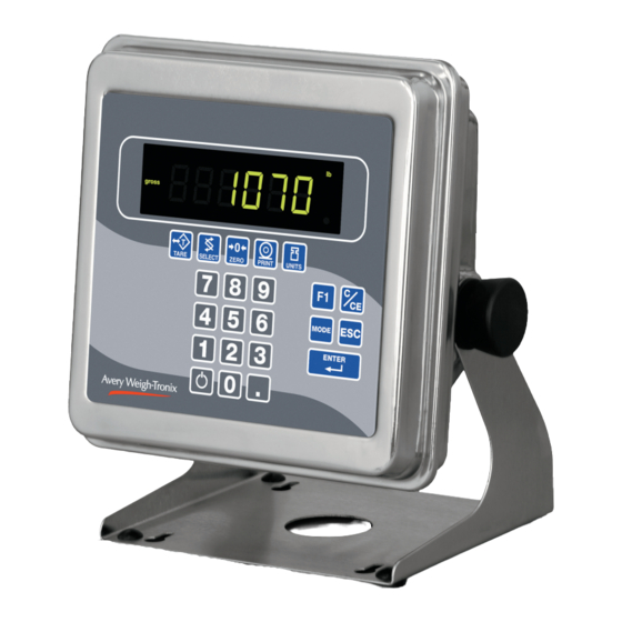
- Page 1 Model E1070 Indicator Service Manual This manual applies to indicator PN 56846-0018 only...
- Page 2 CAUTION: DANGER OF EXPLOSION IF BATTERY IS INCORRECTLY REPLACED. REPLACE ONLY WITH THE SAME OR EQUIVALENT TYPE RECOMMENDED BY THE MANUFACTURER. DISPOSE OF USED BATTERIES ACCORDING TO THE MANUFACTURER'S INSTRUCTIONS. ATTENTION: IL Y A DANGER D'EXPLOSION S'IL Y A REMPLACEMENT INCORRECT DE LA BATTERIE, REMPLACER UNIQUEMENT AVEC UNE BATTERIE DU MÊME TYPE OU D'UN TYPE ÉQUIVALENT RECOMMANDÉ...
-
Page 3: Table Of Contents
Table of Contents Introduction ........................ 5 About This Manual ....................5 Front Panel ........................ 5 Keys ........................6 Annunciators ......................7 Error Messages ......................8 Menu Structure ......................9 Accessing the Menus ................... 9 User Menu ......................10 Service Menu ..................... 12 CAL submenu for analog scales .............. - Page 4 Specifications Power requirements Standard inputs • 85-265 Volts AC @ 0.3Amp maximum • Three logic level inputs for: Zero, Print, Tare, • 50/60 Hz Units, F1, Start and Stop Excitation Standard outputs • +/- 5 volts DC • 10/100 Ethernet (Modbus/TCP, TCP/IP, SMTP, •...
-
Page 5: Introduction
Introduction This manual covers the information you need to configure and service your About This Manual Model E1070 Indicator. Major sections of this manual are headed by titles in a black bar like Intro- duction above. Subheadings appear in the left column. Instructions and text appear on the right side of the page. -
Page 6: Keys
The functions of the keys on the front panel are listed below. Keys Press the TARE key to perform a tare function. Also acts as a left arrow key when in the menus. Never press a key with any- thing but your finger. Damage Press the SELECT key to toggle between Gross, Tare, Net, to the overlay may result if Count, Gross Accumulator, Net Accumulator, Transaction... -
Page 7: Annunciators
There are several annunciators around the edge of the display. The illustra- Annunciators tion below explains each one. Checkweighing Custom Unit graph Kilogram Motion Pound Gross weight Center of zero Accumulator, Output 3 Count Net weight Output 2 Network & Output 1 Tare weight SensorComm... -
Page 8: Error Messages
Error Messages The following are displays you may see if problems occur or if invalid operations are attempted with your indicator: Display Description Overrange weight. Underrange weight. The unit cannot perform a function. Displayed only while key is held down. Displayed while a key is pressed when attempting to modify a sealed selection without edit privileges. -
Page 9: Menu Structure
Menu Structure There are several menus you use to setup or service the Model E1070. You access the menus through the front panel. Each menu is briefly described here. For in depth information about a menu, go to that menu's section in this manual. -
Page 10: User Menu
The User menu lets you test various functions of the indicator. The User User Menu menu is shown in Figure 2. While in a menu, the fan graphs at the top of the display flash as a reminder. Figure 2 User menu flowchart Following are specific instructions for the User menu. - Page 11 User Menu—(continued) 8. Press the PRINT key to perform a dynamic test of the display. . . Display lights all digits and annunciators and continues to flash. 9. Press ESC key to stop the dynamic test. 10. Press the UNITS key. . . BUTTON is displayed.
-
Page 12: Service Menu
The first level of the Service menu is shown in Figure 3. Under these items Service Menu you can do most of the configuration and calibration procedures to ready the indicator for use. Other items are covered in the Supervisor menu covered later in this manual. - Page 13 Service Menu—Analog CAL submenu (continued) 3. Remove all weight from the scale and press the ENTER key. . . Live weight is shown. 4. Press the ENTER key to perform the zero procedure. . . Press the ESC key to abort calibration.
- Page 14 Service Menu—Analog CAL submenu (continued) 6. Press the UNITS key to move to the next calibration point. . . 3 is displayed. 7. Repeat steps 3-6 for cal point 3 and 4. When you are done 4 will be displayed. 8a.
- Page 15 Service Menu—Analog CAL submenu (continued) DISP 1. From previous step 9 press the UNITS key. . . (Live Weight Display) DISP is displayed. Use this item to view the live weight on the scale without exiting the Service menu. 2. Press the PRINT key. . . The live weight is displayed.
-
Page 16: Scale Submenu
Use this section of the Service menu for scale configuration. Figure 5 shows SCALE submenu the flowchart of this menu item. Follow the directions and explanations below to set up these items. Figure 5 Scale submenu flowchart 1. Continue from previous step 4a or access the Service menu. . . CAL is displayed. - Page 17 Service Menu—SCALE submenu (continued) CAP. 1. From previous step 5, press the UNITS key. . . (Capacity) CAP. is displayed. Use this item to set the capacity for the scale. 2. Press the PRINT key. . . The current capacity value is shown. 3.
- Page 18 Service Menu—SCALE submenu (continued) You can have up to three units of measure active. They are lbs, kgs, or a UNITS custom unit of measure. (Unit of measure) Follow these steps: 1. From previous step 3, press the UNITS key. . . UNITS is displayed.
- Page 19 Service Menu—SCALE submenu (continued) STABLE Use this item to define the stability window in terms of ±X divisions for a (Stability window) period of time, in seconds, you set. 1. From previous step 9 press the UNITS key. . . STABLE is displayed.
- Page 20 Service Menu—SCALE submenu (continued) Use this item to set the division size and seconds. The division size you pick (Automatic Zero Tracking) defines a range above and below zero. When scale weight is inside this range for the number of seconds you picked, ½ of the weight will be zeroed. The indicator will repeat removing ½...
- Page 21 Service Menu—SCALE submenu (continued) TARE Use this item to set the tare function parameters; (Tare parameters) Clear tare If you enable (ON) this item, the tare will be automati- cally cleared when the weight falls below the value set under the G-Band menu item. Pushbutton tare If you enable this item (ON), you can use the TARE key to tare a weight from the scale.
- Page 22 UPDATE Use this item to set the number of display updates/second. Choices are 1, 2, (Display Update Rate) 5 and 10 times/second. 10 is the default value. 1. From previous step 11, press the UNITS key. . . UPDATE is displayed. 2.
- Page 23 Service Menu—SCALE submenu (continued) FILTER Use this item to set the noise filtering parameters. (Noise filtering) 1. From previous step 3, press the UNITS key. . . FILTER is displayed. 2. Press the PRINT key. . . Current setting is displayed. Choices are OFF, FLTR 1 and FLTR Off means no filtering.
- Page 24 Service Menu—SCALE submenu (continued) 7. Press the UNITS key. . . THRESH is displayed. This stands for Threshold, the 2nd filtering parameter. Threshold causes the indicator to respond quickly to large weight changes. Threshold is the amount of weight change, in calibration units, beyond which the filtering will be temporarily disabled.
- Page 25 Service Menu—SCALE submenu (continued) 0-RANGE Use this item to key in a percentage of capacity, within which the ZERO key (Zero range) will zero the scale. 1. From previous step 3, press the UNITS key. . . 0-RNGE is displayed. 2.
- Page 26 Service Menu—SCALE submenu (continued) C-ZERO This item is to set the window size for the center-of-zero annunciator. You (Center of zero window) can choose between ±¼ and ±½ division. When the weight falls within the window size, the center-of-zero annunciator lights. 1.
-
Page 27: App Submenu
The next section of the Service menu is the APP submenu. See Figure 6. APP submenu This menu lets you choose the default parameters for your location and also lets you enable or disable each application available in this indicator. Under each enabled application you can edit the default print format (#0) and choose which formats (#0-10) to print and through which port. - Page 28 Service Menu—APP submenu (continued) 1. From previous step 5, press the UNITS key. . . (Accumulator application) ACC. is displayed. This stands for the Accumulator application. 2. Press the PRINT key. . . ON or OFF is displayed, depending on the current setting. 3.
- Page 29 Service Menu—APP submenu (continued) 10. Press the SELECT key. . . ACC. is displayed. 11. Press the UNITS key. . . BATCH is displayed. 1. From previous step 11, press the PRINT key. . . BATCH (Batch application) Repeat steps 2-9 from the ACC (Accumulator application) section to set up the Batch application.
- Page 30 Service Menu—APP submenu (continued) 1. From previous step 3 in section TOP (Peak hold application), press the R-DISP UNITS key. . . (Remote Display) R-DISP is displayed. This stands for remote display. Use this item to set up your indicator as a remote display for another indicator. 2.
-
Page 31: Extra Info: Print Format Editing
Extra Info: Print Format Editing The first three numbers are the sequence of the print commands. The last two characters are the hexadecimal number for the print command. Use the keys as described in Figure 7 to scroll through the se- quence and change the hex. - Page 32 The top line consists of the following commands: ACT<sp>DSP<sp>UN<CR><LF> “G” for gross weight = Active value- “T” for tare weight “N” for net weight = space = Displayed Weight = space = Unit of measure = Carriage return = Line feed When this sequence is sent to a printer, one of the printouts shown above is produced.
- Page 33 Table 1 Printable characters chart Model E1070 Indicator Service Manual...
- Page 34 Table 2 Printing commands chart Token Application Group Parameter GWT(,n) Gross Weight [1] Weight OPTIONAL, (ASCII) Range: (‘2’-‘9’), Indicator Default: ‘6’ NWT(,n) Net Weight [1] Weight OPTIONAL, (ASCII) Range: (‘2’-‘9’), Indicator Default: ‘6’ SAT(,n) Semi-Auto Tare [1] Weight OPTIONAL, (ASCII) Range: (‘2’-‘9’), Indicator Default: ‘6’...
- Page 35 Token Application Group Parameter PLU ID Remote Display Status Miscellaneous Software Version Number Miscellaneous Weight Steady Weight Tare associated with the PLU PLU Totals Information PLU Count Total Net Accumulator Gross Accumulator DSP(,n) Print the displayed weight Weight OPTIONAL, (ASCII) Range: (‘2’-‘9’), Indicator Default: ‘6’...
-
Page 36: Serial Submenu
The next section of the Service menu is the SERIAL submenu. See Figure SERIAL submenu 8. This menu lets you choose the configure the serial ports and create custom print formats #1-10. Figure 8 SERIAL (serial communication) submenu The default serial port param- Follow these steps to access each item in the SERIAL menu and to under- eters are 9600 baud, 8 dat- stand what they do and how to set them:... - Page 37 Service Menu—SERIAL submenu (continued) BAUD 5. Press the PRINT key . . . (Baud rate) Current baud rate is displayed. Choices are from 300 to 115,200. Default is 9600. 6. Scroll the choices by using the TARE or UNITS key and press the ENTER key to accept the displayed choice.
- Page 38 Service Menu—SERIAL submenu (continued) TYPE 1. From previous step 3, press the UNITS key. . . (Serial port mode ) TYPE is displayed. Use this item to set the port mode. 2. Press the PRINT key. . . Current setting is displayed. These are the choices you scroll through in step 3: This stands for enquire.
- Page 39 Stable: Change the stability setting for the Enquire mode. This can be set to YES which will require that there is no motion on the scale for a response to be sent or NO. Press the PRINT key with Stable displayed. Either YES or NO will be displayed depending on the previous setting.
- Page 40 Service Menu—SERIAL submenu (continued) B-CAST 1. With B-CAST displayed, press the PRINT key. . . Current update rate is displayed. Choices are 1/sec, 2/sec, 5/sec, and 10/sec. 2. Scroll through the choices using the TARE or UNITS key. Press the ENTER key when your choice is displayed.
- Page 41 Service Menu—SERIAL submenu (continued) <LF>N<CR> 1st N sends the scale type; S or C. TYP:S = scale, TYP:C = Classifier The I and N commands are related. An I command must be 2nd N sends CAP:uuu:c..c:n:d where sent before the first N com- uuu = unit of measure mand is sent.
- Page 42 Service Menu—SERIAL submenu (continued) R-DISP 1. With R-DISP displayed, press the PRINT key. . . Current setting is displayed. Use this item to choose what style of output you want for this indicator as a master indicator going to a remote display.
- Page 43 Service Menu—SERIAL submenu (continued) RS-485 This section applies only if you are configuring Port 1: 1. With RS485 displayed, press the PRINT key. adr XX is displayed. This is the slave address of the indicator. 2. Press the ENTER key to accept the displayed address or key in a new value then press ENTER.
- Page 44 Service Menu—SERIAL submenu (continued) A-PRINT 1. From previous step 1 in the previous section, press the UNITS key. . . (Autoprint minimum A-PRNT is displayed. Use this item to set a minimum weight, as a trigger weight) percentage of capacity, under which the indicator will send out the configured print format when the weight is stable (no motion).
- Page 45 Service Menu—SERIAL submenu (continued) STRING Use the String item to create customized print formats. The default print (Custom print formats) format is always = 0 and it is edited under the APP menu item. Use the STRING menu to create formats #1-10. These formats are called from application specific settings or from Serial menu item settings.
-
Page 46: Test Submenu
The next section of the Service menu is the TEST submenu. See Figure 9. TEST submenu This menu lets you view indicator information and test the display, keypad, serial ports, inputs and outputs. Figure 9 TEST (diagnostic) submenu Follow these steps to access each item in the Test submenu and to under- stand what they do and how to set them: 1. - Page 47 Service Menu—TEST submenu (continued) 10. Press the SELECT. . . ADC is displayed. 11. Press the UNITS key. . . DISP (Display test) DISP is displayed. This is the display test item. 12. Press the PRINT key to perform a dynamic test of the display. 13.
- Page 48 Service Menu—TEST submenu (continued) INPUT 17. Press the UNITS key. . . (Input test) INPUT is displayed. This is the input test item. 18. Press the PRINT key to access the test. 1 2 3 is displayed. 1 stands for input 1, etc. 19.
- Page 49 Service Menu—TEST submenu (continued) 31. Key in a percentage between 0 and 100 and press the ENTER key. . . The analog output will put out that percentage of voltage. For example: If you have output set from 0 to 10V and you key in a percentage of 25, the analog output voltage should read 2.5 volts.
- Page 50 Service Menu—TEST submenu (continued) 43. Press the UNITS key. . . NETS test NETS is displayed. 44. Press the PRINT key. . . NET 1 is displayed. 45. Toggle between Net 1 or Net 2 using the TARE or UNITS key and press PRINT when the network you want to view is displayed.
-
Page 51: Audit Submenu
The next section of the Service menu is the AUDIT submenu. See Figure AUDIT submenu 10. This menu lets you view configuration and calibration audit counters. These counters cannot be changed, only viewed. Figure 10 AUDIT submenu Follow these steps to access each item in the AUDIT menu: 1. -
Page 52: Input Submenu
The next section of the Service menu is the INPUT submenu. See Figure INPUT submenu 11. This menu lets you configure the inputs of the indicator. Figure 11 INPUT submenu Follow these steps to access and configure the inputs: 1. Access the Service menu. . . CAL is displayed. - Page 53 Service Menu—INPUT submenu (continued) 4. Scroll through the choices by using the TARE or UNITS key and press the ENTER key to accept the displayed choice. . . The input #is displayed. 5. Repeat steps 3 and 4 for each input. 6.
-
Page 54: Output Submenu
The next section of the Service menu is the OUTPUT submenu. See Figure OUTPUT submenu 12. This menu lets you configure the outputs of the indicator. Outputs must be enabled to use the cutoff (trips) operation in each of the applications. If the batch application is enabled, outputs are automatically enabled. -
Page 55: Option Submenu
The next section of the Service menu is the OPTION submenu. See Figure OPTION submenu 13. This menu lets you configure analog output, a pulse counter, Sensor- Comm and networks. Figure 13 OPTION submenu Model E1070 Indicator Service Manual... - Page 56 Service Menu—OPTION submenu (continued) Follow these steps to access and configure the options: 1. Access the Service menu. . . CAL is displayed. 2. Press the UNITS key repeatedly until. . . OPTION is displayed. 3. Press the PRINT key. . . A-OUT (Analog Output) A-OUT is displayed.
- Page 57 Service Menu—OPTION submenu (continued) 15. Press the UNITS key. . . CAL is displayed. Use this to calibrate the analog output. 16. Press the ENTER key. . . ZERO is displayed. Use this to set the analog output zero point. 17.
- Page 58 Service Menu—OPTION submenu (continued) Follow these steps to configure the pulse counter. CNTR 1. From previous step 24, press the UNITS key. . . (Pulse counter ) Optional circuitry required CNTR is displayed. This stands for the pulse counter option. Use this item to enable and enter a factor for converting pulses into your unit of measure.
- Page 59 Service Menu—OPTION submenu (continued) 8. Toggle between the choices by pressing the TARE or UNITS key. When your choice is displayed, press the ENTER key. . . ENABLE is displayed. 9. Press the UNITS key. . . WARN is displayed. Use this to set the zero drift as a percentage of total capacity which will cause a warning to be logged.
- Page 60 Service Menu—OPTION submenu (continued) 21. Press the UNITS key. . . CELLS is displayed. Use this to check the mV/V level of each cell. 22. Press the PRINT key. . . 1 is displayed. This stands for cell 1. 23. Press the PRINT key. . . ON or OFF is shown for the chose cell.
- Page 61 Service Menu—OPTION submenu (continued) 1. If D-NET (DeviceNet™) was selected in step 5 above. . . (NETS) DEVICENET™ NODE will appear on the display. 2. Press the PRINT key. The node address that is currently set is displayed. 3. Key in the desired node address for the DeviceNet™ connection, or press ENTER to accept the node address that is currently configured.
- Page 62 Service Menu—OPTION submenu (continued) 16. Press the PRINT key. . . The display will show something change to “000 FF”, or something similar. The 000 is the type of input and the FF is the input token. A list of input tokens and types is shown in Table 4. 17.
- Page 63 Service Menu—OPTION submenu (continued) 1. If you selected P-BUS (PROFIBUS®) at the beginning of the NETS (NETS) PROFIBUS® setup. . . NODE will appear on the display. 2. Press the PRINT key. The node address that is currently set is displayed. 3.
- Page 64 Service Menu—OPTION submenu (continued) 14. Press the UNITS key. . . IN is displayed. 15. Press the PRINT key. DATA 1 is displayed. 16. Press the PRINT key. . . The display will show something change to “000 FF”, or something similar.
- Page 65 Service Menu—OPTION submenu (continued) 1. If you selected C-NET (ControlNet™) at the beginning of the NETS (NETS) CONTROLNET setup. . (Optional circuitry required) NODE will appear on the display. 2. Press the PRINT key. The node address that is currently set is displayed. 3.
- Page 66 Service Menu—OPTION submenu (continued) 15. You can configure up to 16 items of information to input into the indica- tor. Press the UNITS key. . . DATA 2 is displayed. 16. Repeat steps 13 and 14 above to configure up to 16 data items. 17.
- Page 67 Service Menu—OPTION submenu (continued) (NETS) 1. If you selected E-NET1 (ETHERNET 1 TCP/IP CLIENT) at the beginning ETHERNET 1 of the NETS setup. . TCP/IP CLIENT IP is displayed. 2. Press the PRINT key to configure the IP address of the indicator. . . The first octet of the IP address is shown.
- Page 68 Service Menu—OPTION submenu (continued) 15. If you are connecting to a mail server and you plan to send e-mails from the indicator, press the PRINT key to enter the IP address of the (host) mail server. This will be a numeric entry in four parts (###. ###. ###. ###) just like the IP address.
- Page 69 Service Menu—OPTION submenu (continued) 29. Press the UNITS key. . . GHOST is displayed. 30. Press the PRINT key. . . ON or OFF is displayed. 31. If the indicator is being connected to a SensorComm junction box and Ghosting is enabled and you want to send and email when a cell is ghosted, select ON.
- Page 70 Service Menu—OPTION submenu (continued) 5. Press the UNITS key. . . SUBNET is displayed. 6. Press the PRINT key to enter the Subnet mask. This will be a numeric entry in four parts just like the ip address. (###. ###. ###. ###). After all four parts of the subnet mask have been entered.
- Page 71 Service Menu—OPTION submenu (continued) 19. When the desired type and token appear on the display, press the ENTER key. . . DATA 1 is displayed. 20. You can configure up to 16 items of information to input into the indica- tor.
- Page 72 Service Menu—OPTION submenu (continued) 3. Use the numeric enter method to enter the desired number for the first octet of the IP address. (###. xxx. xxx. xxx). . . The second octet of the IP address is shown. 4. Repeat step 4 for all 4 octet numbers of the IP address. (###. ###. ###. ###).
- Page 73 Service Menu—OPTION submenu (continued) 17. Press the PRINT key. . . The display will show something change to 000 FF, or something similar. The 000 is the type of input and the FF is the input token. A list of input tokens and types is shown in Table 4. 18.
- Page 74 Service Menu—OPTION submenu (continued) 1. If rio (Remote I/O) was selected in step 5 above. . . (NETS) Remote I/O Baud appears on the display. 2. Press the PRINT key. The current baud rate is displayed. This may be “57.6” (57.6k), “115.2”...
- Page 75 Service Menu—OPTION submenu (continued) 15. Toggle between “yes” and “no” with the TARE or UNITS key. Press the PRINT key when the value you want is displayed. LRACK is displayed. 16. Press the UNITS key IOTYPE is displayed. 17. Press the PRINT key to configure the IO Type. The current setting for IO Type is displayed.
- Page 76 Service Menu—OPTION submenu (continued) 29. Use the TARE or UNITS key to change the input type. Use the SELECT or PRINT key to change the input token. When the desired type and token appear on the display, press the F1 key. . . DATA 1 is displayed.
- Page 77 Service Menu—OPTION submenu (continued) (NETS) 1. If you selected E-NET4 (ETHERNET 4 TCP/IP Server) at the beginning ETHERNET 4 of the NETS setup. . TCP/ IP Server IP is displayed. 2. Press the PRINT key to configure the IP address of the indicator. . . The first octet of the IP address is shown.
- Page 78 Service Menu—OPTION submenu (continued) 16. Press the UNITS key. . . EMAIL is displayed. 17. If you want the indicator to automatically send an email when an error occurs, press the PRINT key to configure this. . . ERR.LOG is displayed. 18.
- Page 79 Service Menu—OPTION submenu (continued) 27. Press the PRINT key… SMA or Enq is displayed. 28. Toggle between the two choices using the TARE and UNITS keys. When the desired choice is shown, press the PRINT key to select it. SMA – the SMA protocol over the Ethernet connection.
- Page 80 Service Menu—OPTION submenu (continued) Table 4 Tokens Token Inbound Outbound Inbound Outbound Token Token to net1 from net 1 to net 2 from net 2 (dec.) (hex) Gross Tare Peak Count PLU Piece weight PLU number PLU Gross Accumulator PLU Net Accumulator PLU Total counter PLU Count Accumulator PLU Tare value...
- Page 81 Service Menu—OPTION submenu (continued) TYPE # Data Type # of Bytes Range of Value Signed Character -127 to 127 Unsigned Character 0 to 255 Signed Integer -32767 to 32767 Unsigned Integer 0 to 65535 Signed Long -2,147,483,647 to 2,147,483,647 Unsigned Long 0 to 4,294,967,295 Float 1.0E...
- Page 82 If the division size of the scale is less than 1, the value that is mapped will be scaled down by 10 . Where X equals the number of digits to the right of the decimal point. Any floating-point values will not be scaled down. Example: Token = 2 (Tare)
-
Page 83: Supervisor Menu
The Supervisor menu is shown in Figure 14. Use this menu to set time and Supervisor Menu date, clear and print reports, perform diagnostic tests and view audit counters. Password for the Supervisor WARNING: Entering this menu and changing settings menu is 1793. -
Page 84: Date (Set Date)
Supervisor Menu—(continued) Password for the Supervisor 1. Access the Supervisor menu by pressing and holding the ESC key for 3- menu is 1793. 5 seconds. . . PASS_ is displayed. 2. Key in the password, 1793, and press ENTER. . . DATE is displayed. -
Page 85: Hour (Set Time)
Supervisor Menu—(continued) 1. From previous step 6, press the UNITS key. . . HOUR (Set time) HOUR is displayed. Set the time in this item. 2. Press the PRINT key. . . TYPE0 is displayed. Time can be in 24 hour or 12 hour styles: 0=HH:MM 1=HH:MM AM/PM 3. - Page 86 Supervisor Menu—(continued) 4. Press the PRINT key. . . PRINT is displayed. Use this item to print out a complete report of The PLU report contains the all application parameters and totals. following information for each of the 11 channels: 5.
- Page 87 Supervisor Menu—(continued) ACC Application 1. From previous step 9, press the UNITS key. . . ACC. is displayed. This stands for the accumulator application. See Figure 15 to reference the 2. Press the PRINT key. . . Supervisor’s menu. PRINT is displayed. Use this item to print out a complete report of accumulator totals for each PLU similar to the one shown below: Channel #: Gross Accum:...
- Page 88 Supervisor Menu—(continued) BATCH Application 1. From previous step 7, press the UNITS key. . . BATCH is displayed. 2. Press the PRINT key. . . PRINT is displayed. Use this item to print out a complete report of accumulator totals. 3.
- Page 89 Supervisor Menu—(continued) 10. Press the UNITS key. . . PREACT is displayed. A preact is the time it takes an ingredient (which is falling from an auger or other feeder) to reach the scale after the auger or feeder is shut off. There will always be material in “free-fall”...
- Page 90 Supervisor Menu—(continued) 19. Press the PRINT key. . . 1 is displayed. This stands for Setpoint 1. 20. Scroll through the choices with the TARE or UNITS key. Press ENTER when your choice is displayed. . . SETPT is displayed. If you chose 1 this ingredient will use output #1.
- Page 91 Supervisor Menu—(continued) 28. Press the UNITS key. . . CLEAR is displayed. Use this item to clear all the information stored for this application. WARNING - Only do this if you are sure you want the information permanently removed! You may want to print out the report before clearing all the infor- mation.
- Page 92 Supervisor Menu—(continued) TARGET application 1. From previous step 33, press the UNITS key. . . (Checkweighing) TARGET is displayed. Use this item to print and clear reports for the checkweigher application and to set the type of sampling to be used, Limit or Sample.
- Page 93 Supervisor Menu—(continued) Press ENTER to accept the displayed choice. . . TRIPS is displayed. 10. Press the UNITS key. . . CLEAR is displayed. Use this item to clear all the information stored for this application. WARNING - Only do this if you are sure you want the information permanently removed! You may want to print out the report before clearing all the infor- mation.
- Page 94 Supervisor Menu—(continued) Count Application 1. From previous step 12, press the UNITS key. . . COUNT is displayed. Use this item to clear and print reports for the count application. 2. Press the PRINT key. . . PRINT is displayed. Use this item to print out a complete report of count application information.
- Page 95 Supervisor Menu—(continued) 11. Press the UNITS key. . . MODE is displayed. Use this to select the sampling mode; Bulk or Dribble. Bulk sampling In this sampling method you place the specified number of items on the scale all at once (in bulk) and the scale automatically starts to calculate piece weight when the weight stabilizes.
- Page 96 Supervisor Menu—(continued) TOP (Peak) Application 1. From previous step 15, press the UNITS key. . . TOP is displayed. Use this item to clear and print reports for the peak application. 2. Press the PRINT key. . . PRINT is displayed. Use this item to print out a complete report of peak application information.
- Page 97 Supervisor Menu—(continued) LOGS 9. Press the UNITS key. . . (Log submenu) LOGS is displayed. The Logs menu item allows you to view, print or clear logs for the following: Calibration Overload and Underload Errors SensorComm Errors Ghost Errors 10. Press the PRINT key. . . CAL is displayed.
- Page 98 Supervisor Menu—(continued) 16. Toggle between CNTR and PRINT by using the TARE or UNITS key and press ENTER when your choice is displayed. . . If you chose CNTR, the overload or underload count will be displayed. If you chose PRINT, you can choose the port to print through and press ENTER.
- Page 99 Supervisor Menu—(continued) 27. Press the PRINT key. . . PRINT is displayed. 28. Press the PRINT key to print the report. Port 1 or PORT 2 is displayed. Use this item to select which port to use for printing the report. 29.
-
Page 100: Test (Test Menu)
Supervisor Menu—(continued) From previous step 34, proceed to the next menu by pressing the TEST UNITS key. . . (Test menu) TEST is displayed. This menu lets you view indicator information and test the display, keypad, serial ports, inputs and outputs. ABOUT 2. - Page 101 Supervisor Menu—(continued) 15. Press the SELECT key. . . PORT1 is displayed. 16. Press the UNITS key. . . PORT 2 is displayed. Repeat steps 11 and 12 to test port 2. 17. Press SELECT key. . . SERIAL is displayed. INPUT 18.
- Page 102 Supervisor Menu—(continued) OPTION 29. Press the UNITS key. . . OPTION is displayed. A-OUT test 30. Press the PRINT key. . . A-OUT is displayed. This stands for the analog output test. 31. Press the PRINT key. . . A numeric entry screen is displayed. 32.
- Page 103 Supervisor Menu—(continued) NETS test 44. Press the UNITS key. . . NETS is displayed. 45. Press the PRINT key. . . NET 1 is displayed. 46. Toggle between Net 1 or Net 2 using the TARE or UNITS key and press PRINT when the network you want to view is displayed.
-
Page 104: Audit (Audit Counters) Menu
Supervisor Menu—(continued) The next section of the Supervisor menu is the AUDIT submenu. This menu AUDIT (Audit counters) lets you view configuration and calibration audit counters. These counters menu cannot be changed, only viewed. Follow these steps to access each item in the AUDIT submenu: 1. -
Page 105: Sensorcomm Hardware Configuration And Calibration
SensorComm Hardware Configuration and Calibration SensorComm will only connect to communications port #1 Com Port #1 RS232, RS485 or SensorComm TX / TXA RTS/TXB RX / RCA CTS/RCB +15VDC Main PCB jumper settings need to be set for RS485. This requires disas- sembly of the indicator and moving the jumper on JMP1 to pins 2 and 3. -
Page 106: Enable/Configure Weigh Bars
1. Access the Service (0701) menu. . . Enable/Configure CAL is displayed. Weigh-Bars 2. Press the TARE key. . . OPTION is displayed. 3. Press the PRINT key. . . A-OUT is displayed. 4. Repeatedly press the UNITS key until SENSOR is displayed. 5. -
Page 107: Cal Submenu For Sensorcomm Scales
If your system is set up for a SensorComm j-box, the shaded portion of the CAL submenu for calibration menu is the first item. See Figure 15. Follow these steps to SensorComm scales corner the system and then continue on with the calibration procedures outlined in CAL submenu for analog scales. -
Page 108: Ghost (Ghost Calibration Factors)
All sensors (1-4) will be dis- 9. Repeat steps 6 through 8 for each sensor. . . played in Calibration. If the The last sensor number will be displayed. sensor is not enabled when you press the PRINT key, the 10. -
Page 109: Sensorcomm Error Messages
SensorComm Error Messages Table 5 SensorComm errors All messages below which mention components are referring to components within the SensorComm product. Error # Error Description of Error Possible Cause Communications error SensorComm not responding -Cable -SensorComm hardware failure -Indicator hardware failure Power fault +Vin, +EXC, or -EXC has fallen out -Power supply failure... -
Page 110: Disassembly And Reassembly
Disassembly and Reassembly If the need arises to replace a component of the indicator, use these instruc- Disassembly tions and illustrations to guide you. See the technical illustrations at the back of this manual for detailed illustrations. 1. Power down the indicator. 2. - Page 111 3. Carefully separate the halves. Disconnect all the cables to the main PC board. See Figure 17. Main PC board Failure to observe proper polarity when replacing battery may cause an explosion. Replace battery only with the same -or- equivalent type recommended by manufac- turer.
-
Page 112: Reassembly
5. Remove the nuts shown in Figure 19 to remove the main PC board. The display board is located under this main board. Refer to the technical illustra- tions in the z-fold pages at the back of this manual for ex- ploded views, system block diagrams, torque specs and much more. -
Page 113: Appendix A: Remote Display Functionality
Appendix A: Remote Display Functionality Command Description of command Z<LF> Emulates a Zero keypress S<LF> Emulates a Select keypress T<LF> Emulates a Tare keypress P<LF> Emulates a Print keypress U<LF> Emulates a Units keypress F<LF> Emulates an F1 keypress G<SP>00000<SP>lb<CR><LF> Remote display input string G<SP>00000<SP>lb<CR><AN1>... - Page 114 Annunciator map Annunciator Byte Bit 7 Bit 6 Bit 5 Bit 4 Bit 3 Bit 2 Bit 1 Bit 0 ROSS ->0<- RINT Peak/Count Cust X=Not applicable UBx = Under Target Bars TGx = The word target has multiple LED’s under it. The x represents which LED to turn on. Opx = Represents the outputs N,et = Net LED’s T,are = Tare LED’s...
-
Page 115: Appendix B: Mainboard Network Led Diagnostics
Appendix B: Mainboard Network LED Diagnostics The network LEDs shown in the photo below are found next to the RJ45 Ethernet connector on the main PC board. Below the photo is a table showing what each LED’s condition means. LED #4 LED #3 LED #2 LED #1... -
Page 116: Appendix C: Network Connections
Appendix C: Network Connections BNC bayonet connector for ControlNet interface when option card is installed. Be sure to use 50 ohm termination resistor on RJ-45 connector for Ethernet 10/100 network. (Connector A) interface DeviceNet PROFIBUS-DP Network Bus Rear Panel DB9 - Female Rear Panel Pin No. - Page 117 Remote I/O board and connector. Model E1070 Indicator Service Manual...
-
Page 118: Appendix D: Complete Menu Structures
Appendix D: Complete Menu Structures Complete Supervisor Menu... - Page 119 Complete Service Menu Complete User Menu...
- Page 120 MODEL E1070 SST INDICATOR ENCLOSURE PARTS AND ASSEMBLY (SEE PARTS LIST NEXT PAGE) (SEE PARTS LIST NEXT PAGE) Note: tighten the strain relief “gland sealing nuts” for Item 20 (thread type “PG7”) to 8-10 in.lbs. [0.9-1.1 N·m]. Item 19 (“PG 13”) and Item 21 (“PG NOTE TORQUE SPEC: 11”) tighten to 18-22 in.
- Page 121 MODEL E1070 SST INDICATOR ENCLOSURE PARTS AND ASSEMBLY (CONTINUED FROM PREVIOUS PAGE) ITEM DESCRIPTION W-T P/N AC Power Cord Assembly 49180-0017mts (110-240VAC, USA) AC Power Cord Assembly (110-240VAC, UK) 49180-0025mts Display/Keypad Board Assembly 55969-0029 Main Board assembly 55965-0015 Cable Assy (power supply board-to-main board) 56848-0016 Front Enclosure Ass’y, E1070, (incl: keypad overlay,...
- Page 122 MODEL E1070 SST INDICATOR DIMENSIONAL OUTLINE DRAWING...
- Page 123 MODEL E1070 SST INDICATOR WALL-MOUNT APPLICATION...
- Page 124 MODEL E1070 SST INDICATOR SYSTEM BLOCK DIAGRAM ControlNet FIELD INSTALL KIT: REMOTE I/O FIELD INSTALL KIT: P/N 57315-0034 P/N 57315-0059 Includes "Network Interface" board, Includes "Network Interface" board, ControlNet board and mtg. hardware. Remote I/O board, and mtg. hardware. NOTE: the "ControlNet kit" or "Remote I/O" kit cannot be installed at the same time as the "Analog Output/Pulse Input Kit".
- Page 125 MODEL E1070 SST INDICATOR KEYPAD & SCHEMATIC, DISPLAY BOARD P/N 55969-0029 and POWER SUPPLY BD. P/N 60071-0016 TARE SELECT ZERO PRINT UNITS MODE ENTER...
- Page 126 MODEL E1070 SST INDICATOR MAIN BOARD ASSY P/N 55965-0015 (See additional warning on inside of front cover.)
- Page 127 MODEL 1070 SST INDICATOR OPTIONAL PC BOARDS Analog out / Pulse Counter in PC BOARD (OPTIONAL) Field Install Kit p/n 57315-0018 (includes Analog out/Pulse Counter Board p/n 55977-0011 & mtg. hardware) ControlNet Field Install Kit (optional) p/n 57315-0034 (includes Interface Board p/n 57143-0016 & ControlNet Board p/n 52611-0044 &...
- Page 128 MODEL E1070 SST INDICATOR I/O EXTERNAL CABLE IDENTIFICATION PIN-OUTS...
- Page 129 MODEL E1070 SST INDICATOR TRIPS INTERFACE UNIT (TIU3) (OPTIONAL) Risk of electrical shock. & ASSEMBLY • No user serviceable parts inside. • Refer servicing to qualified service personnel. ITEM DESCRIPTION W-T P/N • Completely disconnect power supply before removing cover. Enclosure 55909-0071 (stainless steel)
- Page 130 Full acknowledgment of the source must be given. Avery Weigh-Tronix is a registered trade mark of the Avery Weigh-Tronix group of companies. This publication was correct at the time of going to print however, Avery Weigh-Tronix reserves the right to alter without notice the specification, design, price or conditions of supply of any product or service at any time.
- Page 131 217 Brunswick Boulevard Pointe Claire, QC H9R 4R7 Canada Weigh Bar ® is a registered trademark Telephone: 514-695-0380 of Avery Weigh-Tronix and may be Toll free: 800-561-9461 registered in certain jurisdictions. Facsimile: 514-695-6820 ODVA™, Ethernet/IP™ and DeviceNet™ are trademarks of ODVA. PROFIBUS is a registered trademark of PROFIBUS International.
Need help?
Do you have a question about the evolution Series and is the answer not in the manual?
Questions and answers