Table of Contents
Advertisement
Quick Links
Advertisement
Table of Contents

Related Manuals for Supermicro SuperServer E102-9W-H


Summary of Contents for Supermicro SuperServer E102-9W-H
- Page 1 SuperServer ® E102-9W-H/E/L/C USER’S MANUAL Revision 1.0b...
- Page 2 State of California, USA. The State of California, County of Santa Clara shall be the exclusive venue for the resolution of any such disputes. Supermicro's total liability for all claims will not exceed the price paid for the hardware product.
- Page 3 About this Manual This manual is written for professional system integrators and PC technicians. It provides information for the installation and use of the SuperServer E102-9W-H/E/L/C. Installation and maintenance should be performed by experienced technicians only. Please refer to the E102-9W-H/E/L/C server specifications page on our website for updates on supported memory, processors and operating systems (http://www.supermicro.com).
-
Page 4: Table Of Contents
SuperServer E102-9W-H/E/L/C User's Manual Contents Chapter 1 Introduction 1.1 Overview ..........................7 1.2 System Features ........................8 1.3 Chassis Features .........................9 Front Features ........................9 Rear Features ........................10 Chassis Dimensions ......................11 1.4 Motherboard Layout ......................12 Quick Reference Table ......................13 System Block Diagram ......................14 1.5 System Installation ......................15... - Page 5 Preface 3.3 Ports ...........................34 Rear I/O Ports ........................34 Control Panel ........................35 3.4 Jumper Settings .........................37 How Jumpers Work ......................37 3.5 LED Indicator ........................39 Chapter 4 Software 4.1 Microsoft Windows OS Installation ..................40 4.2 Driver Installation ........................42 4.3 SuperDoctor 5 ........................43 ®...
- Page 6 SuperServer E102-9W-H/E/L/C User's Manual Contacting Supermicro Headquarters Address: Super Micro Computer, Inc. 980 Rock Ave. San Jose, CA 95131 U.S.A. Tel: +1 (408) 503-8000 Fax: +1 (408) 503-8008 Email: marketing@supermicro.com (General Information) support@supermicro.com (Technical Support) Website: www.supermicro.com Europe Address: Super Micro Computer B.V.
-
Page 7: Chapter 1 Introduction
Product drivers and utilities: https://www.supermicro.com/wdl/driver • Product safety info: http://www.supermicro.com/about/policies/safety_information.cfm • If you have any questions, please contact our support team at: support@supermicro.com This manual may be periodically updated without notice. Check the Supermicro website for possible updates to the manual revision level. -
Page 8: System Features
SuperServer E102-9W-H/E/L/C User's Manual 1.2 System Features The following table provides an overview of the main features of the E102-9W-H/E/L/C. Refer to Appendix C for additional specifications. System Features Motherboards X11SWN-H, X11SWN-E, X11SWN-L, X11SWN-C Chassis CSE-E102 E102-9W-C supports Intel® Celeron 4305UE Processor E102-9W-H, E102-9W-E, and E102-9W-L support Intel®... -
Page 9: Chassis Features
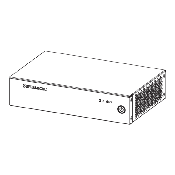
Chapter 1: Introduction 1.3 Chassis Features Front Features See the illustration below for the features included on the front of the chassis. Figure 1-1. Front View Front Chassis Features Item Feature Description The power switch applies or removes power to the system. Turning off power Power Button removes the main power but maintains standby power. -
Page 10: Rear Features
SuperServer E102-9W-H/E/L/C User's Manual Rear Features The chassis rear holds input/output ports, described in Chapter 3. Figure 1-2. Rear View Rear Chassis Features Item Features Description Power Input Use this port for the 60W DC power input 2x 1GbE network ports 4x USB 3.1 ports... -
Page 11: Chassis Dimensions
Chapter 1: Introduction Chassis Dimensions The compact chassis measures 190 x 121 mm from the top view and 190 x 43.6 mm from the I/O view. 190 mm Figure 1-3. Chassis Dimensions (Top View) Figure 1-4. Chassis Dimensions (I/O View) -
Page 12: Motherboard Layout
SuperServer E102-9W-H/E/L/C User's Manual 1.4 Motherboard Layout Below is a layout of the X11SWN-H with jumper, connector, and LED locations shown. See the table on the following page for descriptions. For detailed descriptions, pinout information, and jumper settings, refer to Chapter 3. -
Page 13: Quick Reference Table
Chapter 1: Introduction Quick Reference Table Jumper Description Default Setting JBT1 CMOS Clear Pins 1-2* Normal Operation Pins 2-3 Clear CMOS JLCDPWR1 LVDS Panel Power Source Selection Pins 1-3* (3.3V) Pins 3-5 (5V) Pins 3-4 (12V) JPF1 Power Force On Pins 1-2* (Force Power ON) Pins 2-3 (Power Button ON) JPME2... -
Page 14: System Block Diagram
SuperServer E102-9W-H/E/L/C User's Manual System Block Diagram DUAL CHANNEL MAX. 32G SO-DIMM Support DDR4 2400 MHz Non-ECC SODIMM DDR4 support DDI1 HDMI1.4 HDMI connector Intel DDI2 DP++ connector PTN3460 LVDS Connector DP to LVDSBridge PCIE[15~13] SATA/PCIe-SSD PCIe Gen3 x 4 PCIE[16]/SATA[2] 8.0GT/s... -
Page 15: System Installation
Chapter 1: Introduction 1.5 System Installation This section provides advice and instructions for mounting your system. The system is shipped with the onboard processor and the motherboard installed in the chassis. Unpacking the System Inspect the box in which the system was shipped and note if it was damaged. If the system itself shows damage, file a damage claim with the carrier. -
Page 16: Chapter 2 Maintenance And Component Installation
SuperServer E102-9W-H/E/L/C User's Manual Chapter 2 Maintenance and Component Installation This chapter provides instructions on installing and replacing main system components. To prevent compatibility issues, only use components that match the specifications and/or part numbers given. Installation or replacement of most components require that power first be removed from the system. -
Page 17: Accessing The System
Chapter 2: Maintenance and Component Installation 2.2 Accessing the System The chassis features a removable top cover. Removing the Top Cover 1. Remove two screws holding the cover at the chassis rear. 2. Slide the cover to the rear as illustrated above to release the cover hooks from the chassis, and lift the cover off. -
Page 18: Motherboard Removal
SuperServer E102-9W-H/E/L/C User's Manual Motherboard Removal The X11SWN-H/E/L/C can be removed from the chassis to install motherboard or chassis components. Removing the Motherboard 1. Remove the top chassis cover as described on the previous page. 2. Remove the four screws holding the motherboard to the chassis floor. -
Page 19: Motherboard Components
64GB of non-ECC SO-DIMM DDR4 memory with speeds of up to 2400 MHz in two memory slots. Note: Check the Supermicro website for recommended memory modules. Installing Memory Caution: Exercise extreme care when installing or removing DIMM modules to prevent damage. - Page 20 SuperServer E102-9W-H/E/L/C User's Manual 3. Insert the SO-DIMM module vertically at about a 45 degree angle. Press down until the module locks into place. 4. The side clips will automatically secure the SO-DIMM module, locking it into place. Locking clip SO-DIMM Removal 1.
-
Page 21: Solid State Storage
Chapter 2: Maintenance and Component Installation Solid State Storage This motherboard supports internally mounted solid state storage cards by means of three M.2 drives. M.2 Connectors Figure 2-4. Installing M.2 Expansion Cards Installing an M.2 Card 1. Gently insert the M.2 card into the connector. 2. -
Page 22: Battery Removal And Installation
SuperServer E102-9W-H/E/L/C User's Manual 2.4 Battery Removal and Installation Battery Removal To remove the battery, follow the steps below: 1. Power off your system and remove the cover as described in Sections 2.1 and 2.2. 2. Remove the battery cable at the BT1 connector on the board. -
Page 23: Chassis Components
Chapter 2: Maintenance and Component Installation 2.5 Chassis Components Installing the Hard Drive The CSE-E102 can accommodate a single fixed 2.5" hard drive of 7 mm height. It is installed to the inside of the bottom cover of the chassis. Use an enterprise quality drive. Figure 2-4. -
Page 24: System Cooling
SuperServer E102-9W-H/E/L/C User's Manual System Cooling The E102-9W-H/E/L/C includes a 40x40x10 mm cooling fan. Installing the System Fan 1. Power down the system and remove the chassis cover as described in Sections 2.1 and 2.2. 2. If the motherboard is installed in the chassis, remove the motherboard from the chassis as described in Section 2.2. -
Page 25: Chapter 3 Motherboard Connections
Chapter 3: Motherboard Connections Chapter 3 Motherboard Connections This section describes the connections on the motherboard and provides pinout definitions. Depending on how the system is configured, not all connections are required. The LEDs on the motherboard are also described here. A motherboard layout indicating component locations can be found in Chapter 1. -
Page 26: Headers And Connectors
SuperServer E102-9W-H/E/L/C User's Manual 3.2 Headers and Connectors Fan Header There is one fan header with 4-pins on the motherboard. Pins 1-3 are backward compatible with traditional 3-pin fans. The onboard fan speeds are controlled by Thermal Management (via Hardware Monitoring) in the BIOS. When using Thermal Management setting, please use all 3-pin fans or all 4-pin fans. - Page 27 Chapter 3: Motherboard Connections M.2 Slots The X11SWN-H/E/L/C motherboard has three M.2 slots. M.2 was formerly known as Next Generation Form Factor (NGFF). M.2 allows for a variety of card sizes, increased functionality, and spatial efficiency. The M.2 slot at JMD1 supports M.2 B-Key SATA 3.1/USB 3.0/USB 2.0 modules with Nano SIM in a 2242/3042/2280 form factor, whereas the M.2 slot at JMD2 supports M.2 E-Key PCIe x1/USB2.0/CNVi modules in a 2230 form factor.
- Page 28 SuperServer E102-9W-H/E/L/C User's Manual M.2 Slots (continued) M.2 Pin Definition (JMD2) Pin# Definition Pin# Definition P3V3SB USB_D+ P3V3SB USB_D- CNV_BT_I2S_SCLK CNV_WR_LANE1_DN CNV_RF_RESET_N CNV_WR_LANE1_DP CNV_BT_I2S_SDO MODEM_CLKREQ CNV_WR_LANE0_DN CNV_WR_LANE0_DP UART_BT_WAKE_N CNV_WR_CLK_DN CNV_BRI_RSP CNV_WR_CLK_DP KEY E KEY E KEY E KEY E KEY E...
- Page 29 Chapter 3: Motherboard Connections M.2 Slots (continued) M.2 Pin Definition (JMD3) Pin# Definition Pin# Definition P3V3 P3V3 PERn3 PERp3 PETn3 P3V3 PETp3 P3V3 P3V3 PERn2 P3V3 PERp2 PETn2 PETp2 PERn1 PERp1 PETn1 PETp1 PERn0/SATA-B+ PERp0/SATA-B- PETn0/SATA-A- PETp0/SATA-A+ PERST# CLKREQ# REFCLKn REFCLKp KEY M KEY M...
- Page 30 SuperServer E102-9W-H/E/L/C User's Manual Battery Connector BT1 is a two-pin connector for an external CMOS battery. This connector is also used to clear the CMOS. To clear the CMOS, remove the battery, short pins 1-2 for more than 10 seconds and then install the battery.
- Page 31 Chapter 3: Motherboard Connections LVDS Connector LVDS1 is the LVDS connector. LVDS (low-voltage differential signaling) is a high-speed digital interface that operates at low power. It is a type of connection that is used with an LVDS LCD panel. The connector combines LCD VCC Power (pins 9-10), LVDS high speed digital interface, backlight power 3.3V (pin 7) and 12V (pins 1-5), backlight enable (pin 15), and dimming control (pin 13).
- Page 32 SuperServer E102-9W-H/E/L/C User's Manual System Management Bus Header A System Management Bus header for additional slave devices or sensors is located at JSMBUS1. See the table below for pin definitions. SMBus Header Pin Definitions Pin# Definition Data Ground Clock Nano SIM Slot...
- Page 33 Chapter 3: Motherboard Connections JEIO1 This EI/O header provides flexibility support for the following functions: PCIe x2, LPC, SMBus, and Power, so that it allows customers to make their own I/O module to fit different kinds of vertical market I/O demands. EI/O Pin Definition Pin#...
-
Page 34: Ports
SuperServer E102-9W-H/E/L/C User's Manual 3.3 Ports Rear I/O Ports See Figure 3-1 below for the locations and descriptions of the various I/O ports on the front of the motherboard. HDMI USB0/1 (3.1) USB2/3 (3.1) FAN1 LAN2 LAN1 JGP1 JLPC80 USB4/5... -
Page 35: Control Panel
JF1 contains header pins for various buttons and indicators that are normally located on a control panel at the front of the chassis. These connectors are designed specifically for use with Supermicro chassis. Refer to the figure below for the descriptions of the front control panel buttons and LED indicators. - Page 36 SuperServer E102-9W-H/E/L/C User's Manual HDD LED The HDD LED connection is located on pins 5 and 6 of JF1. Attach a cable here to show hard drive activity status. Refer to the table below for pin definitions. HDD LED Pin Definitions (JF1)
-
Page 37: Jumper Settings
Chapter 3: Motherboard Connections 3.4 Jumper Settings How Jumpers Work To modify the operation of the motherboard, jumpers can be used to choose between optional settings. Jumpers create shorts between two pins to change the function of the connector. Pin 1 is identified with a square solder pad on the printed circuit board. See the diagram below for an example of jumping pins 1 and 2. - Page 38 SuperServer E102-9W-H/E/L/C User's Manual Manufacturing Mode Select Close pins 2-3 of jumper JPME2 to bypass SPI flash security and force the system to operate in the manufacturing mode, which will allow the user to flash the system firmware from a host server for system setting modifications.
-
Page 39: Led Indicator
Chapter 3: Motherboard Connections 3.5 LED Indicator LAN Port LEDs Each Ethernet LAN port has two LEDs. The yellow LED on the right side indicates link and activity, while the left LED may be green, amber, or off to indicate the speed of the connection. LAN1/2 LED (Connection Speed Indicator) -
Page 40: Chapter 4 Software
USB/SATA DVD drive, or a USB flash drive, or the IPMI KVM console. 2. Retrieve the proper RST/RSTe driver. Go to the Supermicro web page for your motherboard and click on "Download the Latest Drivers and Utilities", select the proper driver, and copy it to a USB flash drive. - Page 41 Chapter 4: Software 4. During Windows Setup, continue to the dialog where you select the drives on which to install Windows. If the disk you want to use is not listed, click on “Load driver” link at the bottom left corner. Figure 4-2.
-
Page 42: Driver Installation
The Supermicro website contains drivers and utilities for your system at https://www. supermicro.com/wdl/driver. Some of these must be installed, such as the chipset driver. After accessing the website, go into the CDR_Images (in the parent directory of the above link) and locate the ISO file for your motherboard. Download this file to a USB flash drive or a DVD. -
Page 43: Superdoctor ® 5
4.3 SuperDoctor ® The Supermicro SuperDoctor 5 is a program that functions in a command-line or web-based interface for Windows and Linux operating systems. The program monitors such system health information as CPU temperature, system voltages, system power consumption, fan speed, and provides alerts via email or Simple Network Management Protocol (SNMP). -
Page 44: Chapter 5 Uefi Bios
SuperServer E102-9W-H/E/L/C User's Manual Chapter 5 UEFI BIOS 5.1 Introduction This chapter describes the AMIBIOS™ Setup utility for the X11SWN-H/E/L/C motherboard. The BIOS is stored on a chip and can be easily upgraded using a flash program. Note: Due to periodic changes to the BIOS, some settings may have been added or deleted and might not yet be recorded in this manual. -
Page 45: Main Setup
Note: The time is in the 24-hour format. For example, 5:30 P.M. appears as 17:30:00. The date's default value is the BIOS build date after RTC reset. Supermicro X11SWN-H/E/L/C BIOS Version This feature displays the version of the BIOS ROM used in the system. - Page 46 SuperServer E102-9W-H/E/L/C User's Manual Memory Information Total Memory This feature displays the total size of memory available in the system.
-
Page 47: Advanced
Chapter 5: UEFI BIOS 5.3 Advanced Use this menu to configure advanced settings. Warning: Take caution when changing the Advanced settings. An incorrect value, a very high DRAM frequency or an incorrect BIOS timing setting may cause the system to malfunction. When this occurs, restore to default manufacturer settings. - Page 48 SuperServer E102-9W-H/E/L/C User's Manual Option ROM Messages Use this feature to set the display mode for the Option ROM. The options are Force BIOS and Keep Current. Wait For "F1" If Error This feature forces the system to wait until the F1 key is pressed if an error occurs. The options are Disabled and Enabled.
- Page 49 Chapter 5: UEFI BIOS CPU Configuration The following CPU information will display: • CPU type • CPU Signature • Microcode Patch • Max CPU Speed • Min CPU Speed • Processor Cores • Hyper Threading Technology • • SMX/TXT •...
- Page 50 SuperServer E102-9W-H/E/L/C User's Manual Hardware Prefetcher (Available when supported by the CPU) If set to Enable, the hardware prefetcher will prefetch streams of data and instructions from the main memory to the L2 cache to improve CPU performance. The options are Disabled and Enabled.
- Page 51 Chapter 5: UEFI BIOS Turbo Mode Select Enable for processor cores to run faster than the frequency specified by the manufacturer. The options are Disabled and Enabled. Package Power Limit MSR Lock Select Enabled to lock the package power limit for the model specific registers. The options are Disabled and Enabled.
- Page 52 SuperServer E102-9W-H/E/L/C User's Manual 4-Core Ratio Limit Override This increases (multiplies) 4 clock speeds in the CPU core in relation to the bus speed when four CPU cores are active. Press "+" or "-" on your keyboard to change the value. Enter 42 to use the manufacture default setting.
- Page 53 Chapter 5: UEFI BIOS Chipset Configuration Warning: Setting the wrong values in the sections below may cause the system to malfunction. System Agent (SA) Configuration Memory Configuration Memory Configuration • Memory RC Version • Memory Frequency • Memory Timing (tCL-tRCD-tRP-tRAS) •...
- Page 54 SuperServer E102-9W-H/E/L/C User's Manual Graphics Configuration Graphics Configuration IGFX VBIOS Version 1015 IGFX GOP Version N/A Internal Graphics Select Auto to keep an internal graphics device installed on an expansion slot supported by the CPU to be automatically enabled. The options are Auto, Disabled, and Enabled.
- Page 55 Chapter 5: UEFI BIOS Aperture Size Use this feature to set the Aperture size, which is the size of system memory reserved by the BIOS for graphics device use. The options are 128MB, 256MB, 512MB, 1024MB, and 2048MB. DVMT Pre-Allocated Dynamic Video Memory Technology (DVMT) allows dynamic allocation of system memory to be used for video devices to ensure best use of available system memory based on the DVMT 5.0 platform.
- Page 56 SuperServer E102-9W-H/E/L/C User's Manual GT - Power Management Control RC6 (Render Standby) Use this feature to enable render standby support. The options are Disabled and En- abled. Maximum GT frequency Use this feature to define the Maximum GT frequency. Choose between 33MHz (RPN) and 1200Mhz (RP0).
- Page 57 Chapter 5: UEFI BIOS PCH-IO Configuration PCH-IO Configuration PCH SKU Name Q370 Stepping B0 PCI Express Configuration DMI Link ASPM Control Use this feature to set the ASPM (Active State Power Management) state on the SA (System Agent) side of the DMI Link. The options are Disabled, L0s, L1, L0sL1, and Auto. Peer Memory Write Enable Use this feature to enable or disable peer memory write.
- Page 58 SuperServer E102-9W-H/E/L/C User's Manual IOAPIC 24-119 Entries Use this feature to enable or disable IOAPIC 24-119 entries. IRQ 24-119 may be used by PCH devices. Disabling those IRQs may cause certain devices to fail. The options are Disabled and Enabled.
- Page 59 Chapter 5: UEFI BIOS Change Settings This feature specifies the base I/O port address and the Interrupt Request address of a serial port specified by the user. Select Auto to allow the BIOS to automatically assign the base I/O and IRQ address. The options are Auto, (IO=2F8h; IRQ=3;), (IO=3F8h; IRQ=3, 4, 5, 6, 7, 9, 10, 11, 12;), (IO=2F8h;...
- Page 60 SuperServer E102-9W-H/E/L/C User's Manual Serial Port 5 Configuration Serial Port 5 Select Enabled to enable the selected onboard serial port. The options are Disabled and Enabled. Device Settings This feature displays the status of a serial port specified by the user.
- Page 61 Chapter 5: UEFI BIOS • System Temperature • PCH Temperature • FAN1 • Vcore • VDIMM • • • AVSB • 3VCC • 3VSB • VBAT Serial Port Console Redirection COM1 - COM6 COM Console Redirection Select Enabled to enable COM Port 1 for Console Redirection, which will allow a client machine to be connected to a host machine at a remote site for networking.
- Page 62 SuperServer E102-9W-H/E/L/C User's Manual COM Bits per second Use this feature to set the transmission speed for a serial port used in Console Redirection. Make sure that the same speed is used in the host computer and the client computer. A lower transmission speed may be required for long and busy lines.
- Page 63 Chapter 5: UEFI BIOS COM Legacy OS Redirection Resolution Use this feature to select the number of rows and columns used in Console Redirection for legacy OS support. The options are 80x24 and 80x25. COM Putty KeyPad This feature selects Function Keys and KeyPad settings for Putty, which is a terminal emulator designed for the Windows OS.
- Page 64 SuperServer E102-9W-H/E/L/C User's Manual Terminal Type Use this feature to select the target terminal emulation type for Console Redirection. Select VT100 to use the ASCII character set. Select VT100+ to add color and function key support. Select ANSI to use the extended ASCII character set. Select VT-UTF8 to use UTF8 encoding to map Unicode characters into one or more bytes.
- Page 65 Chapter 5: UEFI BIOS Storage Option ROM/UEFI Driver Select UEFI to load the EFI driver for system boot. Select Legacy to load a legacy driver for system boot. The options are Do not Launch, EFI, and Legacy. Serial ATA Port 0 - 2 This feature displays the information detected on the installed SATA drive on the particular SATA port.
- Page 66 SuperServer E102-9W-H/E/L/C User's Manual AMT BIOS Features Disable this feature to deny access to the MEBx setup. The options are Disabled and Enabled. *If the feature "AMT BIOS Features" is set to Enabled, the AMT Configuration submenu will be available for configuration: AMT Configuration...
- Page 67 Chapter 5: UEFI BIOS OS Timer / BIOS Timer These options appear if Watch Dog (above) is enabled. This is a timed delay in seconds, before a system power down or reset after a BIOS or operating system failure is detected. Enter the value in seconds.
- Page 68 SuperServer E102-9W-H/E/L/C User's Manual MEBx Resolution Settings Non-UI Mode Resolution Use this feature to specify the resolution for the non-UI text mode. The options are Auto, 80x25, and 100x31. UI Mode Resolution Use this feature to specify the resolution for the UI text mode. The options are Auto, 80x25, and 100x31.
- Page 69 Chapter 5: UEFI BIOS Headless Mode Support Enable this feature for the system to function without a keyboard, monitor, or mouse attached. The options are Disabled and Enabled. USB Configuration USB Configuration USB Module Version: 21 USB Controllers: 1 XHCI USB Devices: 1 Keyboard Legacy USB Support Select Enabled to support onboard legacy USB devices.
- Page 70 SuperServer E102-9W-H/E/L/C User's Manual SR-IOV Support Use this feature to enable or disable Single Root IO Virtualization Support. The options are Disabled and Enabled. BME DMA Mitigation Enable this feature to help block DMA attacks. The options are Disabled and Enabled.
- Page 71 Chapter 5: UEFI BIOS Onboard LAN2 Option ROM Use this feature to select which firmware function to be loaded for LAN port 2 used for system boot. The options are Disabled, PXE, and iSCSI. Network Stack Select Enabled to enable PXE (Preboot Execution Environment) or UEFI (Unified Extensible Firmware Interface) for network stack support.
- Page 72 SuperServer E102-9W-H/E/L/C User's Manual HTTP BOOT Configuration HTTP BOOT Configuration Http Boot One Time Use this feature to create the HTTP boot option. The options are Disabled and Enabled. Input the description Highlight the feature and press enter to create a description.
- Page 73 Chapter 5: UEFI BIOS Pending Operation Use this feature to schedule a TPM-related operation to be performed by a security device for system data integrity. The options are None and TPM Clear. Note: Your system will reboot to carry out a pending TPM operation. Pending Operation Use this feature to schedule a TPM-related operation to be performed by a security device for system data integrity.
-
Page 74: Security
SuperServer E102-9W-H/E/L/C User's Manual 5.4 Security Use this menu to configure the security settings. Password Check Select Setup for the system to check for a password at Setup. Select Always for the system to check for a password at bootup or upon entering the BIOS Setup utility. The options are Setup and Always. - Page 75 Chapter 5: UEFI BIOS Secure Boot System Mode Secure Boot Attempt Secure Boot Select Enable for secure boot support to ensure system security at bootup. The options are Disabled and Enabled. Secure Boot Mode This feature allows you to select the desired secure boot mode for the system. The options are Standard and Custom.
- Page 76 SuperServer E102-9W-H/E/L/C User's Manual Device Guard Ready Remove 'UEFI CA' from DB Use this feature to remove the Microsoft UEFI CA certificate from the database. The options are Yes and No. Restore DB Defaults Select Yes to restore all DBs to the default settings. The options are Yes and No.
- Page 77 Chapter 5: UEFI BIOS Authorized TimeStamps Update Select Yes to load a factory default dbt or No to load from a file on an external media. Append Select Yes to add the dbt from the manufacturer's defaults list to the existing dbt. Select No to load the dbt from a file.
-
Page 78: Boot
SuperServer E102-9W-H/E/L/C User's Manual 5.5 Boot Use this menu to configure boot settings: Setup Prompt Timeout Use this feature to specify the length of time (in seconds) for the BIOS to wait before rebooting the system when the setup activation key is pressed. Enter the value of 65535 (0xFFFF) for the BIOS to wait indefinitely. - Page 79 Chapter 5: UEFI BIOS • Boot Option #4 • Boot Option #5 • Boot Option #6 • Boot Option #7 • Boot Option #8 • Boot Option #9 • Boot Option #10 • Boot Option #11 • Boot Option #12 •...
-
Page 80: Save & Exit
SuperServer E102-9W-H/E/L/C User's Manual 5.6 Save & Exit Use this menu to configure save and exit settings. Save Options Discard Changes and Exit Select this feature to quit the BIOS Setup without making any permanent changes to the system configuration and reboot the computer. Select Discard Changes and Exit from the Exit menu and press <Enter>. - Page 81 Chapter 5: UEFI BIOS Default Options Restore Defaults To set this feature, select Restore Optimized Defaults and press <Enter>. These are factory settings designed for maximum system performance but not for maximum stability. Save as User Defaults To set this feature, select Save as User Defaults from the Exit menu and press <Enter>. This enables the user to save any changes to the BIOS setup for future use.
-
Page 82: Appendix A Bios Error Codes
When BIOS performs the Power-On Self-Test, it writes checkpoint codes to I/O port 0080h. If the computer cannot complete the boot process, a diagnostic card can be attached to the computer to read I/O port 0080h (Supermicro p/n AOC-LPC80-20). For information on AMI updates, please refer to http://www.ami.com/products/. -
Page 83: Appendix B Standardized Warning Statements For Ac Systems
Supermicro's Technical Support department for assistance. Only certified technicians should attempt to install or configure components. Read this appendix in its entirety before installing or configuring components in the Supermicro chassis. These warnings may also be found on our website at http://www.supermicro.com/about/... - Page 84 SuperServer E102-9W-H/E/L/C User's Manual Warnung WICHTIGE SICHERHEITSHINWEISE Dieses Warnsymbol bedeutet Gefahr. Sie befinden sich in einer Situation, die zu Verletzungen führen kann. Machen Sie sich vor der Arbeit mit Geräten mit den Gefahren elektrischer Schaltungen und den üblichen Verfahren zur Vorbeugung vor Unfällen vertraut. Suchen Sie mit der am Ende jeder Warnung angegebenen Anweisungsnummer nach der jeweiligen Übersetzung in den übersetzten Sicherheitshinweisen, die zusammen mit diesem Gerät...
- Page 85 Appendix B: Standardized Warning Statements . ٌ ا ك ً ف حالة و ٌ يك أى تتسبب ف اصابة جسذ ة ٌ هذا الزهز ع ٌ خطز !تحذ ز قبل أى تعول عىل أي هعذات،يك عىل علن بالوخاطز ال ا ٌجوة عي الذوائز ٍ...
- Page 86 SuperServer E102-9W-H/E/L/C User's Manual Warnung Vor dem Anschließen des Systems an die Stromquelle die Installationsanweisungen lesen. ¡Advertencia! Lea las instrucciones de instalación antes de conectar el sistema a la red de alimentación. Attention Avant de brancher le système sur la source d'alimentation, consulter les directives d'installation.
- Page 87 Appendix B: Standardized Warning Statements Warnung Dieses Produkt ist darauf angewiesen, dass im Gebäude ein Kurzschluss- bzw. Überstromschutz installiert ist. Stellen Sie sicher, dass der Nennwert der Schutzvorrichtung nicht mehr als: 250 V, 20 A beträgt. ¡Advertencia! Este equipo utiliza el sistema de protección contra cortocircuitos (o sobrecorrientes) del edificio.
- Page 88 SuperServer E102-9W-H/E/L/C User's Manual Power Disconnection Warning Warning! The system must be disconnected from all sources of power and the power cord removed from the power supply module(s) before accessing the chassis interior to install or remove system components. 電源切断の警告...
- Page 89 Appendix B: Standardized Warning Statements אזהרה מפני ניתוק חשמלי !אזהרה יש לנתק את המערכת מכל מקורות החשמל ויש להסיר את כבל החשמלי מהספק .לפני גישה לחלק הפנימי של המארז לצורך התקנת או הסרת רכיבים يجب فصم اننظاو من جميع مصادر انطاقت وإ ز انت سهك انكهرباء من وحدة امداد انطاقت...
- Page 90 SuperServer E102-9W-H/E/L/C User's Manual Attention Il est vivement recommandé de confier l'installation, le remplacement et la maintenance de ces équipements à des personnels qualifiés et expérimentés. !אזהרה .צוות מוסמך בלבד רשאי להתקין, להחליף את הציוד או לתת שירות עבור הציוד...
- Page 91 Appendix B: Standardized Warning Statements Warnung Diese Einheit ist zur Installation in Bereichen mit beschränktem Zutritt vorgesehen. Der Zutritt zu derartigen Bereichen ist nur mit einem Spezialwerkzeug, Schloss und Schlüssel oder einer sonstigen Sicherheitsvorkehrung möglich. ¡Advertencia! Esta unidad ha sido diseñada para instalación en áreas de acceso restringido. Sólo puede obtenerse acceso a una de estas áreas mediante la utilización de una herramienta especial, cerradura con llave u otro medio de seguridad.
- Page 92 SuperServer E102-9W-H/E/L/C User's Manual Battery Handling Warning! There is the danger of explosion if the battery is replaced incorrectly. Replace the battery only with the same or equivalent type recommended by the manufacturer. Dispose of used batteries according to the manufacturer's instructions 電池の取り扱い...
- Page 93 Appendix B: Standardized Warning Statements هناك خطر من انفجار يف حالة اسحبذال البطارية بطريقة غري صحيحة فعليل اسحبذال البطارية فقط بنفس النىع أو ما يعادلها مام أوصث به الرشمة املصنعة جخلص من البطاريات املسحعملة وفقا لحعليامت الرشمة الصانعة 경고! 배터리가 올바르게 교체되지 않으면 폭발의 위험이 있습니다. 기존 배터리와 동일하거나 제 조사에서...
- Page 94 SuperServer E102-9W-H/E/L/C User's Manual ¡Advertencia! Puede que esta unidad tenga más de una conexión para fuentes de alimentación. Para cortar por completo el suministro de energía, deben desconectarse todas las conexiones. Attention Cette unité peut avoir plus d'une connexion d'alimentation. Pour supprimer toute tension et tout courant électrique de l'unité, toutes les connexions d'alimentation doivent être débranchées.
- Page 95 Appendix B: Standardized Warning Statements Backplane Voltage Warning! Hazardous voltage or energy is present on the backplane when the system is operating. Use caution when servicing. バックプレーンの電圧 システムの稼働中は危険な電圧または電力が、 バックプレーン上にかかっています。 修理する際には注意く ださい。 警告 当系统正在进行时,背板上有很危险的电压或能量,进行维修时务必小心。 警告 當系統正在進行時,背板上有危險的電壓或能量,進行維修時務必小心。 Warnung Wenn das System in Betrieb ist, treten auf der Rückwandplatine gefährliche Spannungen oder Energien auf.
- Page 96 SuperServer E102-9W-H/E/L/C User's Manual هناك خطز مه التيار الكهزبايئ أوالطاقة املىجىدة عىل اللىحة عندما يكىن النظام يعمل كه حذ ر ا عند خدمة هذا الجهاس 경고! 시스템이 동작 중일 때 후면판 (Backplane)에는 위험한 전압이나 에너지가 발생 합니다. 서비스 작업 시 주의하십시오.
- Page 97 Appendix B: Standardized Warning Statements תיאום חוקי החשמל הארצי !אזהרה .התקנת הציוד חייבת להיות תואמת לחוקי החשמל המקומיים והארציים تركيب املعدات الكهربائية يجب أن ميتثل للقىاويه املحلية والىطىية املتعلقة بالكهرباء 경고! 현 지역 및 국가의 전기 규정에 따라 장비를 설치해야 합니다. Waarschuwing Bij installatie van de apparatuur moet worden voldaan aan de lokale en nationale elektriciteitsvoorschriften.
- Page 98 SuperServer E102-9W-H/E/L/C User's Manual Attention La mise au rebut ou le recyclage de ce produit sont généralement soumis à des lois et/ou directives de respect de l'environnement. Renseignez-vous auprès de l'organisme compétent. סילוק המוצר !אזהרה .סילוק סופי של מוצר זה חייב להיות בהתאם להנחיות וחוקי המדינה...
- Page 99 Appendix B: Standardized Warning Statements Warnung Gefährlich Bewegende Teile. Von den bewegenden Lüfterblätter fern halten. Die Lüfter drehen sich u. U. noch, wenn die Lüfterbaugruppe aus dem Chassis genommen wird. Halten Sie Finger, Schraubendreher und andere Gegenstände von den Öffnungen des Lüftergehäuses entfernt.
- Page 100 Verbindungskabeln, Stromkabeln und/oder Adapater, die Ihre örtlichen Sicherheitsstandards einhalten. Der Gebrauch von anderen Kabeln und Adapter können Fehlfunktionen oder Feuer verursachen. Die Richtlinien untersagen das Nutzen von UL oder CAS zertifizierten Kabeln (mit UL/CSA gekennzeichnet), an Geräten oder Produkten die nicht mit Supermicro gekennzeichnet sind.
- Page 101 حجم املوصل والقابس السليم. استخدام أي كابالت ومحوالت أخرى قد يتسبب يف عطل أو حريق. يحظر قانون السالمة لألجهزة الكهربائية واملعدات استخدام الكابالت املعتمدة من قبلUL أوCSA ( والتي تحمل عالمةUL/CSA) مع أي معدات أخرى غري املنتجات املعنية واملحددة من قبلSupermicro.
- Page 102 사항을 준수하여 제공되거나 지정된 연결 혹은 구매 케이블, 전원 케이블 및 AC 어댑터를 사용하십시오. 다른 케이블이나 어댑터를 사용하면 오작동이나 화재가 발생할 수 있습니다. 전기 용품 안전법은 UL 또는 CSA 인증 케이블 (코드에 UL / CSA가 표시된 케이블)을 Supermicro 가 지정한 제품 이외의 전기 장치에 사용하는 것을 금지합니다. Stroomkabel en AC-Adapter...
-
Page 103: Appendix C System Specifications
Appendix C: System Specifications Appendix C System Specifications Processors E102-9W-C supports Intel® Celeron 4305UE Processor E102-9W-H, E102-9W-E, and E102-9W-L support Intel® Whiskey Lake-U i7-8665UE/i5-8365UE/i3-8145UE Note: Please refer to the motherboard specifications pages on our website for updates to supported processors BIOS 256Mb SPI MX25L25673 Memory... - Page 104 SuperServer E102-9W-H/E/L/C User's Manual Regulatory Compliance FCC, ICES, CE, VCCI, RCM, NRTL, CB Applied Directives, Standards EMC/EMI: 2014/30/EU (EMC Directive) FCC Part 15 ICE-003 VCCI 32-1 AS/NZS CISPR 32 EN55032 EN55035 CISPR 24 CISPR 32: 2015 EN 61000-3-2 EN 61000-3-3...
Need help?
Do you have a question about the SuperServer E102-9W-H and is the answer not in the manual?
Questions and answers