Table of Contents
Advertisement
Quick Links
Advertisement
Table of Contents

Related Manuals for Supermicro SuperServer E301-9D-8CN8TP


Summary of Contents for Supermicro SuperServer E301-9D-8CN8TP
- Page 1 SuperServer ® E301-9D-8CN8TP USER’S MANUAL Revision 1.0...
- Page 2 State of California, USA. The State of California, County of Santa Clara shall be the exclusive venue for the resolution of any such disputes. Supermicro's total liability for all claims will not exceed the price paid for the hardware product.
- Page 3 Preface About this Manual This manual is written for professional system integrators and PC technicians. It provides information for the installation and use of the SuperServer E301-9D-8CN8TP. Installation and maintenance should be performed by experienced technicians only. Notes For your system to work properly, please follow the links below to download all necessary drivers, utilities and the user’s manual for your server.
-
Page 4: Table Of Contents
SuperServer E301-9D-8CN8TP User's Manual Contents Chapter 1 Introduction 1.1 Overview ..........................7 1.2 System Features ........................8 1.3 Chassis Features .........................9 Front Features ........................9 Rear Features ........................10 1.4 Motherboard Layout ......................11 Quick Reference Table ......................12 System Block Diagram ......................14 1.5 Server Installation and Setup .....................15 Unpacking the System ......................15... - Page 5 Preface 4.6 LED Indicators ........................41 Chapter 4 Software 4.1 Microsoft Windows OS Installation ..................43 4.2 Driver Installation ........................45 4.3 SuperDoctor 5 ........................46 ® 4.4 IPMI ............................47 Chapter 5 UEFI BIOS 5.1 Introduction .........................48 Starting the Setup Utility ....................48 5.2 Main Menu ..........................49 5.3 Advanced Settings Menu ....................51 5.4 Event Logs .........................79 5.5 IPMI ............................81...
- Page 6 SuperServer E301-9D-8CN8TP User's Manual Contacting Supermicro Headquarters Address: Super Micro Computer, Inc. 980 Rock Ave. San Jose, CA 95131 U.S.A. Tel: +1 (408) 503-8000 Fax: +1 (408) 503-8008 Email: marketing@supermicro.com (General Information) support@supermicro.com (Technical Support) Website: www.supermicro.com Europe Address: Super Micro Computer B.V.
-
Page 7: Chapter 1 Introduction
Introduction 1.1 Overview The SuperServer E301-9D-8CN8TP is a compact, embedded system comprised of the SCE301 chassis and the X11SDV-8C-TP8F single processor motherboard. Refer to our website for information on operating systems that have been certified for use with the system (www.supermicro.com). -
Page 8: System Features
SuperServer E301-9D-8CN8TP User's Manual 1.2 System Features The following table provides an overview of the main features of the E301-9D-8CN8TP. Please refer to Appendix C for additional specifications. System Features Motherboard X11SDV-8C-TP8F Chassis SCE301 Intel® Xeon® D-2146NT SoC Chipset System on Chip BIOS 512Mb AMI BIOS®... -
Page 9: Chassis Features
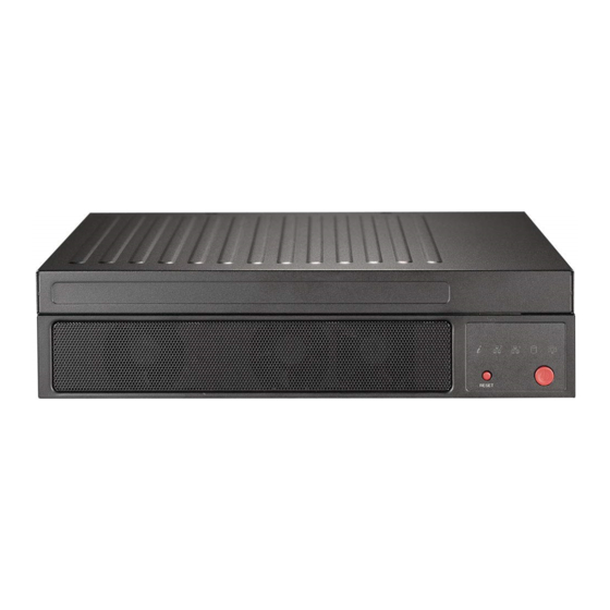
Chapter 1: Introduction 1.3 Chassis Features The SCE301 is a compact embedded 1U chassis for Mini ITX and Flex ATX motherboards. Front Features The front of the chassis includes the control panel. Figure 1-1. Chassis Front and Control Panel Control Panel Features Item Features Description... -
Page 10: Rear Features
SuperServer E301-9D-8CN8TP User's Manual Rear Features The chassis rear holds input/output ports, a K-slot and a PCI-E slot. Figure 1-2. Rear Chassis View Rear Chassis Features Item Features Description The main power switch applies or removes primary power from the power supply Power Input to the server but maintains standby power. -
Page 11: Motherboard Layout
Chapter 1: Introduction 1.4 Motherboard Layout Below is a layout of the X11SDV-8C-TP8F with jumper, connector and LED locations shown. See the table on the following page for descriptions. For detailed descriptions, pin-out information and jumper settings, refer to Chapter 3. JMD1_SRW1 LEDM1 SLOT6... -
Page 12: Quick Reference Table
SuperServer E301-9D-8CN8TP User's Manual Quick Reference Table Jumper Description Default Setting JBT1 CMOS Clear Open: Normal, Closed: Clear CMOS JI2C1, JI2C2 SMB to PCI-E Slots Enable/Disable Pins 2-3 (Disabled) JNS1 Mini-SAS HDD NVMe/SATA Mode Select Pins 1-2: SATA (Default) Pins 2-3: NVMe... - Page 13 Chapter 1: Introduction Connector Description JPV1 12V 8-pin DC Power Connector (Required to provide extra power to CPU, or as alternative power for special enclosure when the 24 pin ATX power is not in use) JSD1 SATA Disk On Module (DOM) Power Connector JSIM1 Nano SIM Slot for M.2 B-Key WAN card support JSMB1...
-
Page 14: System Block Diagram
SuperServer E301-9D-8CN8TP User's Manual System Block Diagram DDR4 1866/2133/2400 DDR4 1866/2133/2400 JLAN2 JLAN1 PCIE 3.0 x8 PCIE 3.0 x4 PE2[15:12] PE2[7:0] JPCIE1 SLOT7 PCIE 3.0 x8 I350 AM4 PCIE 3.0 x16 JPCIE2 SLOT6 PCIE 3.0 x16 PE1[15:0] PCIE 3.0 x4 M.2(M-key)CONN... -
Page 15: Server Installation And Setup
Chapter 1: Introduction 1.5 Server Installation and Setup The server is shipped with the onboard processor and the motherboard installed in the chassis. Several steps are necessary to begin using your server. You must add memory, mount the hard disk drive, and mount the system in place. Unpacking the System Inspect the box in which the system was shipped and note if it was damaged. -
Page 16: Installing Rack Mounting Brackets
SuperServer E301-9D-8CN8TP User's Manual Installing Rack Mounting Brackets The chassis can be mounted in a rack using two rack brackets and a two-part power adapter shelf bracket (optional, MCP-290-30002-0B). 1. Attach the rack brackets using three screws through the holes in each bracket to secure the bracket to the chassis. -
Page 17: Chapter 2 Maintenance And Component Installation
Chapter 2: Maintenance and Component Installation Chapter 2 Maintenance and Component Installation This chapter provides instructions on installing and replacing main system components. To prevent compatibility issues, only use components that match the specifications and/or part numbers given. Installation or replacement of most components require that power first be removed from the system. -
Page 18: Accessing The System
SuperServer E301-9D-8CN8TP User's Manual 2.2 Accessing the System The SCE301 features a removable top cover to access the inside of the chassis. Figure 2-1. Removing the Chassis Cover Removing the Top Cover 1. Power down the system as described in section 2.1. -
Page 19: Motherboard Components
The X11SDV-8C-TP8F supports up to 256GB of ECC regular DIMM or 512GB of ECC LRDIMM DDR4 memory with speeds of up to 2666MHz in four memory slots. Note: Check the Supermicro website for recommended memory modules. Memory Population Guidelines For optimal memory performance, follow the table below when populating memory. -
Page 20: Dimm Module Population Sequence
SuperServer E301-9D-8CN8TP User's Manual DIMM Module Population Sequence When installing memory modules, the DIMM slots should be populated in the following order: DIMMB1, DIMMA1, DIMME1, DIMMD1. • Always use DDR4 DIMM modules of the same type, size, and speed. •... -
Page 21: Motherboard Battery
Chapter 2: Maintenance and Component Installation Motherboard Battery The motherboard uses non-volatile memory to retain system information when system power is removed. This memory is powered by a lithium battery residing on the motherboard. Replacing the Battery Begin by removing power from the system as described in section 3.1. 1. -
Page 22: Chassis Components
SuperServer E301-9D-8CN8TP User's Manual 2.4 Chassis Components Installing the Storage Drive The SCE301 can accommodate two fixed 2.5" storage drives of 15 mm height or four 2.5" drives of 9.5 mm height, installed to a mounting tray inside the chassis. - Page 23 Chapter 2: Maintenance and Component Installation Figure 2-5. Installing 15 mm 2.5" Hard Drives 4. Place up to two 15 mm 2.5" drives directly into the tray and secure it to the tray with the screws provided with the drive. Figure 2-6.
-
Page 24: System Cooling
SuperServer E301-9D-8CN8TP User's Manual System Cooling The SCE301 includes two replaceable 4-cm fans. An optional third fan can be purchased. Installing or Replacing the System Fan 1. Power down the system as described in section 2.1 and remove the AC power cord and the chassis cover. -
Page 25: Chapter 3 Motherboard Connections
Chapter 3: Motherboard Connections Chapter 3 Motherboard Connections This section describes the connections on the X11SDV-8C-TP8F motherboard and provides pinout definitions. Note that depending on how the system is configured, not all connections are required. The LEDs on the motherboard are also described here. A motherboard layout indicating component locations may be found in Chapter 1. - Page 26 SuperServer E301-9D-8CN8TP User's Manual Important: To provide adequate power to the motherboard, connect the 24-pin and the 8-pin power connectors to the power supply. Failure to do so may void the manufacturer's warranty on your power supply and motherboard. Secondary Power Connector JPV1 must also be connected to the power supply.
-
Page 27: Headers And Connectors
Chapter 3: Motherboard Connections 3.2 Headers and Connectors Fan Headers The X11SDV-8C-TP8F has six 4-pin fan headers (FAN1 ~ FAN4, FANA, FANB). These headers are backward compatible with the traditional 3-pin fans. However, fan speed control is available for 4-pin fans only by Thermal Management via the IPMI 2.0 interface. Refer to the table below for pin definitions. - Page 28 NC = No Connection NVMe I C Header JNVI2C1 is a management header for the Supermicro AOC NVMe PCI-E peripheral cards. Connect a corresponding I C cable to this header. Refer to the table below for pin definitions. C Header...
- Page 29 Chapter 3: Motherboard Connections Disk On Module Power Connector One power connector for a SATA DOM (Disk On Module) device is located at JSD1. Connect the appropriate cable here to provide power support for your Serial Link DOM device. DOM Power Pin Definitions Pin# Definition...
- Page 30 SuperServer E301-9D-8CN8TP User's Manual TPM/Port 80 Header A Trusted Platform Module (TPM)/Port 80 header is located at JTPM1 to provide TPM support and a Port 80 connection. Use this header to enhance system performance and data security. Refer to the table below for pin definitions.
- Page 31 Chapter 3: Motherboard Connections LAN Activity Header JLANLED1 is the activity LED header for LAN1 through LAN4. LAN Activity LED Pin Definitions Pin# Definition 3V3 Stby LAN3_ACT_N 3V3 Stby LAN4_ACT_N LAN Activity LED Headers JTGLED1 is the activity LED header for LAN7 and LAN8, and JTGLED2 is the activity header for LAN5 and LAN6.
-
Page 32: Control Panel
JF1 contains header pins for various buttons and indicators that are normally located on a control panel at the front of the chassis. These connectors are designed specifically for use with Supermicro chassis. See the figure below for the descriptions of the front control panel buttons and LED indicators. - Page 33 Chapter 3: Motherboard Connections Reset Button The Reset Button connection is located on pins 3 and 4 of JF1. Attach it to a hardware reset switch on the computer case. Refer the table below for pin definitions. Reset Button Pin Definitions (JF1) Pin# Definition Reset...
- Page 34 SuperServer E301-9D-8CN8TP User's Manual NIC1/NIC2 Activity LED The NIC (Network Interface Controller) LED connection for LAN port 1 is located on pins 11 and 12 of JF1, and the LED connection for LAN port 2 is on pins 9 and 10. Attach the NIC LED cables here to display network activity.
-
Page 35: Ports
Chapter 3: Motherboard Connections 3.3 Ports Figure 3-1. I/O Port Locations and Definitions Rear I/O Ports Description Description Description IPMI LAN LAN5 LAN1 SFP LAN8 USB5 3.0 ports LAN4 LAN3 SFP LAN7 USB4 3.0 ports LAN6 LAN2 VGA Port A VGA video port is located near LAN ports 7/8 on the I/O back panel. LAN Ports There are eight LAN ports located on the I/O back panel of the motherboard. - Page 36 SuperServer E301-9D-8CN8TP User's Manual Universal Serial Bus (USB) Ports There are two USB 3.0 ports (USB4/5) on the I/O back panel. The motherboard also has two front access USB 2.0 headers (USB0/1, USB2/3). The onboard headers can be used to provide front side USB access with a cable (not included).
- Page 37 Note: UID can also be triggered via IPMI on the motherboard. For more information on IPMI, please refer to the IPMI User's Guide posted on our website at https://www.supermicro.com/ support/manuals/. UID Button...
-
Page 38: Jumpers
SuperServer E301-9D-8CN8TP User's Manual 3.4 Jumpers Explanation of Jumpers To modify the operation of the motherboard, jumpers are used to choose between optional settings. Jumpers create shorts between two pins to change the function associated with it. Pin 1 is identified with a square solder pad on the printed circuit board. See the motherboard layout page for jumper locations. - Page 39 Chapter 3: Motherboard Connections LAN Port Enable/Disable Use jumper JPL1 to enable or disable LAN1 - LAN4. Refer to the table below for jumper settings. LAN Port Enable/Disable Jumper Settings Jumper Setting Definition Pins 1-2 Enabled (Deafult) Pins 2-3 Disabled Manufacturing Mode Select Close pins 2-3 of jumper JPME2 to bypass SPI flash security and force the system to operate in the manufacturing mode, which will allow the user to flash the system firmware from a host...
- Page 40 SuperServer E301-9D-8CN8TP User's Manual SMBus to PCI-E Slots Use jumpers JI2C1 and JI2C2 to enable PCI-E SMB (System Management Bus) support to improve system management for the onboard PCI-E slot. SMBus to PCI-E Slots Jumper Settings Jumper Setting Definition Pins 1-2...
-
Page 41: Led Indicators
Chapter 3: Motherboard Connections 4.6 LED Indicators LAN LEDs Eight LAN ports (LAN1 - LAN8) are located on the I/O back panel. Each Ethernet LAN port has two LEDs. The green LED indicates activity, while the other Link LED may be green, amber, or off to indicate the speed of the connection. - Page 42 SuperServer E301-9D-8CN8TP User's Manual BMC Heartbeat LED LEDM1 is the BMC heartbeat LED. When the LED is blinking green, BMC is working. Refer to the table below for the LED status. BMC Heartbeat LED Indicator LED Color Definition Blinking Green...
-
Page 43: Chapter 4 Software
USB/SATA DVD drive, or a USB flash drive, or the IPMI KVM console. 2. Retrieve the proper RST/RSTe driver. Go to the Supermicro web page for your motherboard and click on "Download the Latest Drivers and Utilities", select the proper driver, and copy it to a USB flash drive. - Page 44 SuperServer E301-9D-8CN8TP User's Manual 4. During Windows Setup, continue to the dialog where you select the drives on which to install Windows. If the disk you want to use is not listed, click on “Load driver” link at the bottom left corner.
-
Page 45: Driver Installation
The Supermicro website contains drivers and utilities for your system at https://www. supermicro.com/wftp/driver. Some of these must be installed, such as the chipset driver. After accessing the website, go into the CDR_Images (in the parent directory of the above link) and locate the ISO file for your motherboard. Download this file to a USB flash drive or a DVD. -
Page 46: Superdoctor ® 5
4.3 SuperDoctor ® The Supermicro SuperDoctor 5 is a program that functions in a command-line or web-based interface for Windows and Linux operating systems. The program monitors such system health information as CPU temperature, system voltages, system power consumption, fan speed, and provides alerts via email or Simple Network Management Protocol (SNMP). -
Page 47: Ipmi
The X11SDV-8C-TP8F supports the Intelligent Platform Management Interface (IPMI). IPMI is used to provide remote access, monitoring and management. There are several BIOS settings that are related to IPMI. For general documentation and information on IPMI, please visit our website at: http://www.supermicro.com/products/nfo/IPMI.cfm. -
Page 48: Chapter 5 Uefi Bios
SuperServer E301-9D-8CN8TP User's Manual Chapter 5 UEFI BIOS 5.1 Introduction This chapter describes the AMIBIOS™ Setup utility for the X11SDV-8C-TP8F motherboard. The BIOS is stored on a chip and can be easily upgraded using a flash program. Note: Due to periodic changes to the BIOS, some settings may have been added or deleted and might not yet be recorded in this manual. -
Page 49: Main Menu
Note: The time is in the 24-hour format. For example, 5:30 P.M. appears as 17:30:00. The date's default value is the BIOS build date after RTC reset. Supermicro X11SDV-8C-TP8F BIOS Version This feature displays the version of the BIOS ROM used in the system. - Page 50 SuperServer E301-9D-8CN8TP User's Manual Memory Information Total Memory This feature displays the total size of memory available in the system. Memory Speed This feature displays the default speed of the memory modules installed in the system.
-
Page 51: Advanced Settings Menu
Chapter 5: UEFI BIOS 5.3 Advanced Settings Menu Use this menu to configure advanced settings. Warning: Take caution when changing the Advanced settings. An incorrect value, a very high DRAM frequency or an incorrect BIOS timing setting may cause the system to malfunction. When this occurs, restore to default manufacturer settings. - Page 52 SuperServer E301-9D-8CN8TP User's Manual Bootup NumLock State Use this feature to set the Power-on state for the Numlock key. The options are Off and On. Wait For "F1" If Error This feature forces the system to wait until the F1 key is pressed if an error occurs. The options are Disabled and Enabled.
- Page 53 Chapter 5: UEFI BIOS CPU Configuration The following CPU information will display: • Processor BSP Revision • Processor Socket • Processor ID • Processor Frequency • Processor Max Ratio • Processor Min Ratio • Microcode Revision • L1 Cache RAM •...
- Page 54 SuperServer E301-9D-8CN8TP User's Manual PPIN Control Select Unlock/Enable to use the Protected Processor Inventory Number (PPIN) in the system. The options are Unlock/Disable and Unlock/Enable. Hardware Prefetcher (Available when supported by the CPU) If set to Enable, the hardware prefetcher will prefetch streams of data and instructions from the main memory to the L2 cache to improve CPU performance.
- Page 55 Chapter 5: UEFI BIOS Power Performance Tuning This feature allows the user to set whether the operating system or the BIOS controls the Energy Performance BIAS (EPB). The options are OS Controls EPB and BIOS Controls EPB. *If the feature above is set to BIOS Controls EPB, the following features will be available for configuration: ENERGY_PERF_BIAS_CFG Mode The Energy Perfomance BIAS (EPB) feature allows the user to configure CPU power...
- Page 56 SuperServer E301-9D-8CN8TP User's Manual Hardware PM State Control Hardware P-States This setting allows the user to select between OS and hardware-controlled P-states. Selecting Native Mode allows the OS to choose a P-state. Selecting Out of Band Mode allows the hardware to autonomously choose a P-state without OS guidance. Selecting Native Mode with No Legacy Support functions as Native Mode with no support for older hardware.
- Page 57 Chapter 5: UEFI BIOS Chipset Configuration Warning: Setting the wrong values in the sections below may cause the system to malfunction. North Bridge Configuration UPI Configuration The following UPI information will display: • Number of CPU • Number of IIO •...
- Page 58 SuperServer E301-9D-8CN8TP User's Manual Sub NUMA Clustering (SNC) is a feature that breaks up the Last Level Cache (LLC) into clusters based on address range. Each cluster is connected to a subset of the memory controller. Enabling SNC improves average latency and reduces memory access conges- tion to achieve higher performance.
- Page 59 Chapter 5: UEFI BIOS Memory Topology This feature displays the information of onboard memory modules as detected by the BIOS. Memory RAS Configuration Static Virtual Lockstep Mode Select Enable to run the system's memory channels in lockstep mode to minimize memory access latency.
- Page 60 SuperServer E301-9D-8CN8TP User's Manual Patrol Scrub Patrol Scrub is a process that allows the CPU to correct correctable memory errors detected on a memory module and send the correction to the requestor (the original source). When this feature is set to Enable, the IO hub will read and write back one cache line every 16K cycles if there is no delay caused by internal processing.
- Page 61 Chapter 5: UEFI BIOS PCI-E Port Link Status This feature shows the status of the device plugged into this slot. PCI-E Port Link Max This feature shows the status of the device plugged into this slot. PCI-E Port Link Speed This feature shows the status of the device plugged into this slot.
- Page 62 SuperServer E301-9D-8CN8TP User's Manual Prioritize TPH Use this feature to enable Prioritize TPH support. The options are Enable and Disable. Relaxed Ordering Select Enable to enable Relaxed Ordering support, which will allow certain transac- tions to violate the strict-ordering rules of PCI bus for a transaction to be completed prior to other transactions that have already been enqueued.
- Page 63 Chapter 5: UEFI BIOS Intel® VMD Technology Intel® VMD for Volume Management Device on CPU VMD Config for PStack0 Intel® VMD for Volume Management Device Select Enable to use the Intel Volume Management Device Technology for this stack. The options are Disable and Enable.
- Page 64 SuperServer E301-9D-8CN8TP User's Manual Port 60/64 Emulation Select Enabled for I/O port 60h/64h emulation support, which in turn, will provide complete legacy USB keyboard support for the operating systems that do not support legacy USB devices. The options are Disabled and Enabled.
- Page 65 Chapter 5: UEFI BIOS *If the feature "Configure SATA as" above is set to RAID, the following features will be available for configuration: SATA RSTe Boot Info Select Enable to provide full int13h support for the devices attached to SATA controller. The options are Disable and Enable.
- Page 66 SuperServer E301-9D-8CN8TP User's Manual SATA HDD Unlock This feature allows the user to remove any password-protected SATA disk drives. The options are Disable and Enable. Aggressive Link Power Management When this feature is set to Enable, the SATA AHCI controller manages the power usage of the SATA link.
- Page 67 Chapter 5: UEFI BIOS PCIe/PCI/PnP Configuration PCIe/PCI/PnP Configuration The following information will display: • PCI Bus Driver Version • PCI Devices Common Settings Above 4G Decoding (Available if the system supports 64-bit PCI decoding) Select Enabled to decode a PCI device that supports 64-bit in the space above 4G Address. The options are Disabled and Enabled.
- Page 68 SuperServer E301-9D-8CN8TP User's Manual VGA Priority Use this feature to select VGA priority when multiple VGA devices are detected. Select On- board to give priority to your onboard video device. Select Offboard to give priority to your graphics card. The options are Onboard and Offboard.
- Page 69 Chapter 5: UEFI BIOS Network Stack Configuration Network Stack Select Enabled to enable PXE (Preboot Execution Environment) or UEFI (Unified Extensible Firmware Interface) for network stack support. The options are Enabled and Disabled. *If the feature above is set to Enabled, the next six features will be available for configuration: Ipv4 PXE Support Select Enabled to enable IPv4 PXE boot support.
- Page 70 SuperServer E301-9D-8CN8TP User's Manual Change Settings This feature specifies the base I/O port address and the Interrupt Request address of Serial Port 1. Select Auto for the BIOS to automatically assign the base I/O and IRQ address to a serial port specified. The options are Auto, (IO=3F8h; IRQ=4), (IO=3F8h; IRQ=3, 4, 5, 6, 7, 9, 10, 11, 12), (IO=2F8h;...
- Page 71 Chapter 5: UEFI BIOS Console Redirection Settings Terminal Type This feature allows the user to select the target terminal emulation type for Console Redirection. Select VT100 to use the ASCII Character set. Select VT100+ to add color and function key support. Select ANSI to use the Extended ASCII Character Set. Select VT-UTF8 to use UTF8 encoding to map Unicode characters into one or more bytes.
- Page 72 SuperServer E301-9D-8CN8TP User's Manual Resolution 100x31 Select Enabled for extended-terminal resolution support. The options are Disabled and Enabled. Legacy OS Redirection Resolution Use this feature to select the number of rows and columns used in Console Redirection for legacy OS support. The options are 80x24 and 80x25.
- Page 73 Chapter 5: UEFI BIOS Data Bits Use this feature to set the data transmission size for Console Redirection. The options are 7 (Bits) and 8 (Bits). Parity A parity bit can be sent along with regular data bits to detect data transmission errors. Select Even if the parity bit is set to 0, and the number of 1's in data bits is even.
- Page 74 SuperServer E301-9D-8CN8TP User's Manual Redirection After BIOS POST Use this feature to enable or disable legacy console redirection after BIOS POST. When set to BootLoader, legacy console redirection is disabled before booting the OS. When set to Always Enable, legacy console redirection remains enabled when booting the OS. The options are Always Enable and BootLoader.
- Page 75 Chapter 5: UEFI BIOS Bits per second This feature sets the transmission speed for a serial port used in Console Redirection. Make sure that the same speed is used in the host computer and the client computer. A lower transmission speed may be required for long and busy lines. The options are 9600, 19200, 57600, and 115200 (bits per second).
- Page 76 This feature displays the status of the TPM support on this motherboard. • TPM Enabled Status • TPM Active Status • TPM Owner Status SMCI BIOS-Based TPM Provision Support Use feature to enable the Supermicro TPM Provision support. The options are Disabled and Enabled.
- Page 77 Chapter 5: UEFI BIOS TXT Support Intel TXT (Trusted Execution Technology) helps protect against software-based attacks and ensures protection, confidentiality and integrity of data stored or created on the system. Use this feature to enable or disable TXT Support. The options are Disabled and Enabled. *The features in the Trusted Computing section on this page and the next are displayed if a TPM 2.0 module is detected: TPM20 Device Found...
- Page 78 Use this feature to disable or enable Platform Hiearchy (PH) Randomization. The options are Disabled and Enabled. SMCI BIOS-Based TPM Provision Support Use feature to enable the Supermicro TPM Provision support. The options are Disabled and Enabled. TXT Support Intel TXT (Trusted Execution Technology) helps protect against software-based attacks and ensures protection, confidentiality and integrity of data stored or created on the system.
-
Page 79: Event Logs
Chapter 5: UEFI BIOS 5.4 Event Logs Use this menu to configure event log settings. Change SMBIOS Event Log Settings Enabling/Disabling Options SMBIOS Event Log Change this feature to enable or disable all features of the SMBIOS Event Logging during system boot. - Page 80 SuperServer E301-9D-8CN8TP User's Manual When Log is Full Select Erase Immediately to immediately erase all errors in the SMBIOS event log when the event log is full. Select Do Nothing for the system to do nothing when the SMBIOS event log is full.
-
Page 81: Ipmi
Chapter 5: UEFI BIOS 5.5 IPMI Use this menu to configure Intelligent Platform Management Interface (IPMI) settings. BMC Firmware Revision This feature indicates the IPMI firmware revision in your system. IPMI STATUS This feature indicates the status of the IPMI firmware installed in your system. System Event Log Enabling/Disabling Options SEL Components... - Page 82 SuperServer E301-9D-8CN8TP User's Manual Erasing Settings Erase SEL Select Yes, On next reset to erase all system event logs upon next system reboot. Select Yes, On every reset to erase all system event logs upon each system reboot. Select No to keep all system event logs after each system reboot.
- Page 83 Chapter 5: UEFI BIOS Station IP Address This feature displays the Station IP address for this computer. This should be in decimal and in dotted quad form (i.e., 192.168.10.253). Subnet Mask This feature displays the sub-network that this computer belongs to. The value of each three-digit number separated by dots should not exceed 255.
- Page 84 The Disable option is for applications that require faster power on time wthout using Supermicro Update Manager (SUM) or extended IPMI features. The BMC network configuration in the BIOS setup is also invalid when IPMI Function Support is disabled.
-
Page 85: Security
Chapter 5: UEFI BIOS 5.6 Security Use this menu to configure the security settings for the system. Administrator Password Use this feature to set the administrator password which is required to enter the BIOS setup utility. The length of the password should be from 3 characters to 20 characters long. Password Check Select Setup for the system to check for a password at Setup. - Page 86 SuperServer E301-9D-8CN8TP User's Manual Secure Boot Mode This feature allows the user to select the desired secure boot mode for the system. The options are Standard and Custom. *If Secure Boot Mode is set to Customized, Key Management features are available...
- Page 87 Chapter 5: UEFI BIOS Platform Key (PK) This feature allows the user to configure the settings of the platform keys. Details Select this feature to view the details of the Platform Key. Export Select Yes to export a PK from a file on an external media. Update Select Yes to load a factory default PK or No to load from a file on an external media.
- Page 88 SuperServer E301-9D-8CN8TP User's Manual Append Select Yes to add the db from the manufacturer's defaults list to the existing db. Select No to load the db from a file. The options are Yes and No. Delete Select Ok to remove the db and then the system will reset to Setup/Audit Mode.
- Page 89 Chapter 5: UEFI BIOS OsRecovery Signatures Details Select this feature to view the details of the dbr. Export Select Yes to export a dbr from a file on an external media. Update Select Yes to load a factory default dbr or No to load from a file on an external media. Append Select Yes to add the dbr from the manufacturer's defaults list to the existing dbr.
-
Page 90: Boot
SuperServer E301-9D-8CN8TP User's Manual 5.7 Boot Use this menu to configure boot settings: Boot mode select Use this feature to select the boot mode. The options are LEGACY, UEFI, and DUAL. Legacy to EFI Support Select Enabled to boot EFI OS support after Legacy boot order has failed. The options are... - Page 91 Chapter 5: UEFI BIOS Fixed BOOT ORDER Priorities This option prioritizes the order of bootable devices that the system to boot from. Press <Enter> on each entry from top to bottom to select devices. • Boot Option #1 • Boot Option #2 •...
-
Page 92: Save & Exit
SuperServer E301-9D-8CN8TP User's Manual 5.8 Save & Exit Use this menu to configure save and exit settings. Save Options Discard Changes and Exit Select this option to quit the BIOS Setup without making any permanent changes to the system configuration and reboot the computer. Select Discard Changes and Exit from the Exit menu and press <Enter>. - Page 93 Chapter 5: UEFI BIOS Default Options Restore Defaults To set this feature, select Restore Optimized Defaults and press <Enter>. These are factory settings designed for maximum system performance but not for maximum stability. Save as User Defaults To set this feature, select Save as User Defaults from the Exit menu and press <Enter>. This enables the user to save any changes to the BIOS setup for future use.
-
Page 94: Appendix A Bios Codes
SuperServer E301-9D-8CN8TP User's Manual Appendix A BIOS Codes A.1 BIOS Error POST (Beep) Codes During the POST (Power-On Self-Test) routines, which are performed each time the system is powered on, errors may occur. Non-fatal errors are those which, in most cases, allow the system to continue the boot-up process. - Page 95 When BIOS performs the Power On Self Test, it writes checkpoint codes to I/O port 0080h. If the computer cannot complete the boot process, a diagnostic card can be attached to the computer to read I/O port 0080h (Supermicro p/n AOC-LPC80-20). For information on AMI updates, please refer to http://www.ami.com/products/.
-
Page 96: Appendix B Standardized Warning Statements For Ac Systems
Supermicro's Technical Support department for assistance. Only certified technicians should attempt to install or configure components. Read this appendix in its entirety before installing or configuring components in the Supermicro chassis. These warnings may also be found on our website at http://www.supermicro.com/about/... - Page 97 Appendix B: Standardized Warning Statements Warnung WICHTIGE SICHERHEITSHINWEISE Dieses Warnsymbol bedeutet Gefahr. Sie befinden sich in einer Situation, die zu Verletzungen führen kann. Machen Sie sich vor der Arbeit mit Geräten mit den Gefahren elektrischer Schaltungen und den üblichen Verfahren zur Vorbeugung vor Unfällen vertraut. Suchen Sie mit der am Ende jeder Warnung angegebenen Anweisungsnummer nach der jeweiligen Übersetzung in den übersetzten Sicherheitshinweisen, die zusammen mit diesem Gerät ausgeliefert wurden.
- Page 98 SuperServer E301-9D-8CN8TP User's Manual . ٌ ا ك ً ف حالة و ٌ يك أى تتسبب ف اصابة جسذ ة ٌ هذا الزهز ع ٌ خطز !تحذ ز قبل أى تعول عىل أي هعذات،يك عىل علن بالوخاطز ال ا ٌجوة عي الذوائز...
- Page 99 Appendix B: Standardized Warning Statements Warnung Vor dem Anschließen des Systems an die Stromquelle die Installationsanweisungen lesen. ¡Advertencia! Lea las instrucciones de instalación antes de conectar el sistema a la red de alimentación. Attention Avant de brancher le système sur la source d'alimentation, consulter les directives d'installation. .יש...
- Page 100 SuperServer E301-9D-8CN8TP User's Manual Warnung Dieses Produkt ist darauf angewiesen, dass im Gebäude ein Kurzschluss- bzw. Überstromschutz installiert ist. Stellen Sie sicher, dass der Nennwert der Schutzvorrichtung nicht mehr als: 250 V, 20 A beträgt. ¡Advertencia! Este equipo utiliza el sistema de protección contra cortocircuitos (o sobrecorrientes) del edificio.
- Page 101 Appendix B: Standardized Warning Statements Power Disconnection Warning Warning! The system must be disconnected from all sources of power and the power cord removed from the power supply module(s) before accessing the chassis interior to install or remove system components. 電源切断の警告...
- Page 102 SuperServer E301-9D-8CN8TP User's Manual يجب فصم اننظاو من جميع مصادر انطاقت وإ ز انت سهك انكهرباء من وحدة امداد انطاقت قبم انىصىل إىن امنناطق انداخهيت نههيكم نتثبيج أو إ ز انت مكىناث الجهاز 경고! 시스템에 부품들을 장착하거나 제거하기 위해서는 섀시 내부에 접근하기 전에 반드시 전원...
- Page 103 Appendix B: Standardized Warning Statements Attention Il est vivement recommandé de confier l'installation, le remplacement et la maintenance de ces équipements à des personnels qualifiés et expérimentés. !אזהרה .צוות מוסמך בלבד רשאי להתקין, להחליף את הציוד או לתת שירות עבור הציוד واملدربيه...
- Page 104 SuperServer E301-9D-8CN8TP User's Manual Warnung Diese Einheit ist zur Installation in Bereichen mit beschränktem Zutritt vorgesehen. Der Zutritt zu derartigen Bereichen ist nur mit einem Spezialwerkzeug, Schloss und Schlüssel oder einer sonstigen Sicherheitsvorkehrung möglich. ¡Advertencia! Esta unidad ha sido diseñada para instalación en áreas de acceso restringido. Sólo puede obtenerse acceso a una de estas áreas mediante la utilización de una herramienta especial,...
- Page 105 Appendix B: Standardized Warning Statements Battery Handling Warning! There is the danger of explosion if the battery is replaced incorrectly. Replace the battery only with the same or equivalent type recommended by the manufacturer. Dispose of used batteries according to the manufacturer's instructions 電池の取り扱い...
- Page 106 SuperServer E301-9D-8CN8TP User's Manual هناك خطر من انفجار يف حالة اسحبذال البطارية بطريقة غري صحيحة فعليل اسحبذال البطارية فقط بنفس النىع أو ما يعادلها مام أوصث به الرشمة املصنعة جخلص من البطاريات املسحعملة وفقا لحعليامت الرشمة الصانعة 경고! 배터리가 올바르게 교체되지 않으면 폭발의 위험이 있습니다. 기존 배터리와 동일하거나 제...
- Page 107 Appendix B: Standardized Warning Statements ¡Advertencia! Puede que esta unidad tenga más de una conexión para fuentes de alimentación. Para cortar por completo el suministro de energía, deben desconectarse todas las conexiones. Attention Cette unité peut avoir plus d'une connexion d'alimentation. Pour supprimer toute tension et tout courant électrique de l'unité, toutes les connexions d'alimentation doivent être débranchées.
- Page 108 SuperServer E301-9D-8CN8TP User's Manual Backplane Voltage Warning! Hazardous voltage or energy is present on the backplane when the system is operating. Use caution when servicing. バックプレーンの電圧 システムの稼働中は危険な電圧または電力が、 バックプレーン上にかかっています。 修理する際には注意く ださい。 警告 当系统正在进行时,背板上有很危险的电压或能量,进行维修时务必小心。 警告 當系統正在進行時,背板上有危險的電壓或能量,進行維修時務必小心。 Warnung Wenn das System in Betrieb ist, treten auf der Rückwandplatine gefährliche Spannungen oder Energien auf.
- Page 109 Appendix B: Standardized Warning Statements هناك خطز مه التيار الكهزبايئ أوالطاقة املىجىدة عىل اللىحة عندما يكىن النظام يعمل كه حذ ر ا عند خدمة هذا الجهاس 경고! 시스템이 동작 중일 때 후면판 (Backplane)에는 위험한 전압이나 에너지가 발생 합니다. 서비스 작업 시 주의하십시오. Waarschuwing Een gevaarlijke spanning of energie is aanwezig op de backplane wanneer het systeem in gebruik is.
- Page 110 SuperServer E301-9D-8CN8TP User's Manual תיאום חוקי החשמל הארצי !אזהרה .התקנת הציוד חייבת להיות תואמת לחוקי החשמל המקומיים והארציים تركيب املعدات الكهربائية يجب أن ميتثل للقىاويه املحلية والىطىية املتعلقة بالكهرباء 경고! 현 지역 및 국가의 전기 규정에 따라 장비를 설치해야 합니다.
- Page 111 Appendix B: Standardized Warning Statements Attention La mise au rebut ou le recyclage de ce produit sont généralement soumis à des lois et/ou directives de respect de l'environnement. Renseignez-vous auprès de l'organisme compétent. סילוק המוצר !אזהרה .סילוק סופי של מוצר זה חייב להיות בהתאם להנחיות וחוקי המדינה التخلص...
- Page 112 SuperServer E301-9D-8CN8TP User's Manual Warnung Gefährlich Bewegende Teile. Von den bewegenden Lüfterblätter fern halten. Die Lüfter drehen sich u. U. noch, wenn die Lüfterbaugruppe aus dem Chassis genommen wird. Halten Sie Finger, Schraubendreher und andere Gegenstände von den Öffnungen des Lüftergehäuses entfernt.
- Page 113 Verbindungskabeln, Stromkabeln und/oder Adapater, die Ihre örtlichen Sicherheitsstandards einhalten. Der Gebrauch von anderen Kabeln und Adapter können Fehlfunktionen oder Feuer verursachen. Die Richtlinien untersagen das Nutzen von UL oder CAS zertifizierten Kabeln (mit UL/CSA gekennzeichnet), an Geräten oder Produkten die nicht mit Supermicro gekennzeichnet sind.
- Page 114 حجم املوصل والقابس السليم. استخدام أي كابالت ومحوالت أخرى قد يتسبب يف عطل أو حريق. يحظر قانون السالمة لألجهزة الكهربائية واملعدات استخدام الكابالت املعتمدة من قبلUL أوCSA ( والتي تحمل عالمةUL/CSA) مع أي معدات أخرى غري املنتجات املعنية واملحددة من قبلSupermicro.
- Page 115 사항을 준수하여 제공되거나 지정된 연결 혹은 구매 케이블, 전원 케이블 및 AC 어댑터를 사용하십시오. 다른 케이블이나 어댑터를 사용하면 오작동이나 화재가 발생할 수 있습니다. 전기 용품 안전법은 UL 또는 CSA 인증 케이블 (코드에 UL / CSA가 표시된 케이블)을 Supermicro 가 지정한 제품 이외의 전기 장치에 사용하는 것을 금지합니다. Stroomkabel en AC-Adapter...
-
Page 116: Appendix C System Specifications
SuperServer E301-9D-8CN8TP User's Manual Appendix C System Specifications Processors Single Intel® Xeon® D-2146NT with 80W TDP Note: Please refer to the motherboard specifications pages on our website for updates to supported processors. BIOS 512Mb AMI BIOS® SPI Flash BIOS Memory... - Page 117 Appendix C: System Specifications Perchlorate Warning California Best Management Practices Regulations for Perchlorate Materials: This Perchlorate warning applies only to products containing CR (Manganese Dioxide) Lithium coin cells. “Perchlorate Material-special handling may apply. See www.dtsc. ca.gov/hazardouswaste/perchlorate”...
Need help?
Do you have a question about the SuperServer E301-9D-8CN8TP and is the answer not in the manual?
Questions and answers