
Related Manuals for LEMKEN Solitair 8+


Summary of Contents for LEMKEN Solitair 8+
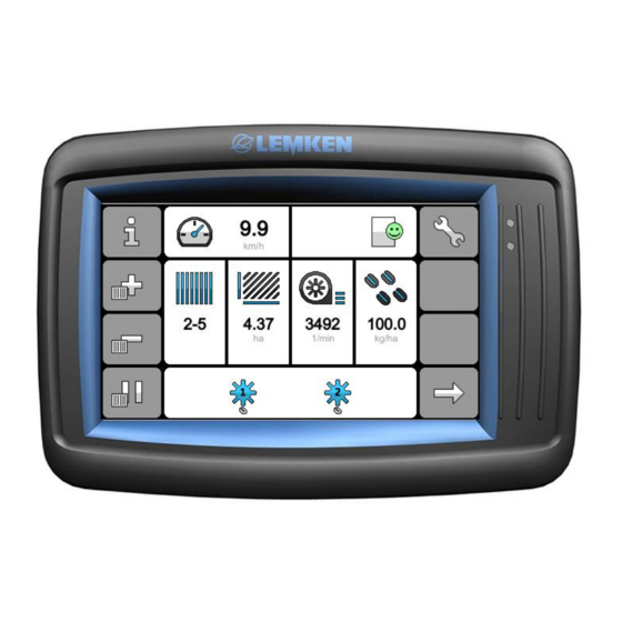
- Page 1 Operating Instructions iQblue EcoDrill V03.00 Solitair 8+ - en - Item no. 17514422 00/02.21 LEMKEN GmbH & Co. KG Weseler Straße 5, 46519 Alpen / Germany Telephone +49 28 02 81 0, Fax +49 28 02 81 220 lemken@lemken.com, www.LEMKEN.com...
- Page 3 However, this brief instruction is not a substitute for thorough study of the operating instructions. These operating instructions will help to familiarise you with the LEMKEN GmbH & Co. KG device and the options available for using it.
- Page 4 Remember that you should only use genuine LEMKEN spare parts. Reproduction parts have a negative influence on the function of the device, have a shorter ser- vice life and present risks and hazards that cannot be estimated by LEMKEN GmbH & Co. KG. They also increase the maintenance costs.
-
Page 5: Table Of Contents
CONTENTS About these operating instructions ................ 6 Proper use........................6 Area of application ......................6 Operation terminal ......................6 1.3.1 Switching on and off ....................7 1.3.2 Taking a screen shot ....................7 Symbols used in the Operating Instructions ............8 Hazard classes ...................... - Page 6 4.5.3 Monitoring: fan ......................28 4.5.4 Monitoring ........................29 4.5.5 Forward speed ......................30 4.5.6 Operation terminal ..................... 31 4.5.7 Service ........................31 Driving on public roads ..................32 Switching off work lighting ..................32 Switching off the operation terminal ................. 32 Preparations prior to operation ................
- Page 7 Set operation terminal, sound and brightness ............58 Checking the status ....................59 7.2.1 Messages ........................59 7.2.2 Operating states ......................59 Procedure for messages .................... 60 7.3.1 Display and remedy messages .................. 60 7.3.2 Hide messages prematurely ..................61 Activating and deactivating alarm functions ............
-
Page 8: About These Operating Instructions
ABOUT THESE OPERATING INSTRUCTIONS Proper use The electronic control system is intended for control, monitoring and adjustment of various LEMKEN implements. The functions of the electronic control system are transmitted to the implement via a special operating terminal. Area of application The control is designed to control, monitor and set the following machines: ... -
Page 9: Switching On And Off
About these operating instructions 1.3.1 Switching on and off Press the switch (1) to the (on/off) posi- tion. 1.3.2 Taking a screen shot The screenshot of the display can be sa- ved in PNG format on the USB stick. ... -
Page 10: Symbols Used In The Operating Instructions
Symbols used in the Operating Instructions SYMBOLS USED IN THE OPERATING INSTRUCTIONS Hazard classes The following symbols are used in the Operating Instructions for particularly im- portant information: DANGER Denotes an imminent hazard with high risk, which will result in death or severe physical injury, if not avoided. -
Page 11: Information
Symbols used in the Operating Instructions Information Denotes special user tips and other particularly useful or important information for operation and efficient utilisation. Environmental protection Indication of special recycling and environmental protection measures. Indication of passages The following symbols are used for particular passages in the operating instruc- tions: ... -
Page 12: Safety
Safety SAFETY Switch off the operating terminal DANGER Risk of accidents due to unintentional activation of the operating terminal Unintentional movement of the implement may occur if the operat- ing terminal is switched on. Ensure that the operating terminal is switched off when travel- ling to the field and on public roads. -
Page 13: Layout And Description
Layout and description LAYOUT AND DESCRIPTION Displays and menus Some displays on the operating terminal may differ from those shown in these ope- rating instructions depending on the im- plement type and the equipment installed. This is pointed out if it is relevant to opera- tion of the implement. -
Page 14: Program Start
Layout and description Menu management The following control elements are availab- le in menu management: (1) Softkey bars for navigation and opera- tion (5) Orientation in text display Selected menu on the machine type Selected menu management Information on page (current page / total number of pages) (6) Displays and functions with colour coding... -
Page 15: Operating Menu
Layout and description Operating menu The operating menu serves to monitor and control the implement during use. Prior to use implement-specific entries and settings for the control are required. 4.3.1 Displays The displays monitor the machine. Also some displays are a quick access to the particular settings or information. - Page 16 Layout and description Display Contents quick access Currently cultivated Information: area [ha] Counters: Job counter Daily counter Annual counter Total counter Operating mode and Function: position of the levelling Lift lower levelling harrow harrows. Current speed of the Settings: fan [rpm] Monitoring fan...
-
Page 17: Softkeys
Layout and description 4.3.2 Softkeys All the softkeys of the operating menu are located in softkey bars. Softkeys with ar- rows are available for navigating through the softkey bars. The arrangement of the softkeys can be adjusted individually. Navigation To navigate through the softkey bars, masks and levels, the following softkeys with arrows are available: Scroll to the next softkey bar or mask. - Page 18 Layout and description Work lighting To switch the work lighting, the following softkey is available: Work lighting on / off Depending on the machine equipment, the function may be integrated in the displays. Tramline mechanism To manually switch the track, the following softkeys are available: Forwards Backwards...
-
Page 19: Information
Layout and description Information The information can be used to check and monitor the implement. Open using the softkey Access to the information The following menus can be selected: «Error log, see page 18» «Counter, see page 19» «Implement configuration, see page 20» «Sensors, see page 21»... -
Page 20: Error Log
Layout and description 4.4.1 Error log The present messages are collected in an error log. The messages can be malfunc- tions, warnings or information. Open via menu The colour of the smiley indicates the most serious message. No fault. There may be information (green) ... -
Page 21: Counter
Layout and description Display message: (Only for information and warnings) On Off 4.4.2 Counter Open via menu Access to the menu management The menu comprises the following coun- ters: Job counter (1/4) Daily counter (2/4) Menu: Information | Counter ... -
Page 22: Implement Configuration
Layout and description 4.4.3 Implement configuration The menu provides an overview of general data and equipment of the machine. Opening via the menu Access to the menu management Menu: Information | Implement configurati- The following displays and functions are available: Implement type Serial number Year of manufacture... -
Page 23: Sensors
Layout and description 4.4.4 Sensors The menu is used to check the function of individual sensors. Opening via the menu Access to the menu management The menu contains several pages. Menu: Information | Sensors Functions and states are monitored with sensors. -
Page 24: Power Supply
Layout and description 4.4.5 Power supply Opening via the menu Access to the menu administration The menu contains several pages. Each control unit is listed on a separate page. Menu: Information | Power supply The following displays and functions are available: Designation of control unit ... -
Page 25: Software Versions
The following displays and functions are available: Job computer Designation of control unit System version: Hardware Operating system Internal storage Application Operation terminal Designation of control unit System version: Serial number Operating system LEMKEN operating system Application... -
Page 26: Metering Units
Layout and description 4.4.7 Metering units The menu shows the current target setting of the metering units. Opening via the menu Access to the menu management Menu: Information | Metering units The following displays and functions are available: Metering wheel ... -
Page 27: Settings
Layout and description Settings The settings can be used to set up the im- plement specifically for each use. Open using the softkey Access to the settings The following menus can be selected: «Calibration, see page 26» «Tramline mechanism, see page 27» «Monitoring: fan, see page 28»... -
Page 28: Calibration
Layout and description 4.5.1 Calibration The menu can be selected in the following operating state: Speed of the fan below 500 rpm Implement has been lifted. The calibration test is used to calibrate the distribution for the machine. Opening via the menu Access to the menu management Menu: Settings | Calibration... -
Page 29: Tramline Mechanism
Layout and description 4.5.2 Tramline mechanism Opening via the menu Access to the menu management Menu: Settings | Tramline mechanism The following displays and functions are available: Tramline mechanism: on/off Working width of cultivating machine [m] Type of pass-over (not relevant for Soli- tair 8+) ... -
Page 30: Monitoring: Fan
Layout and description 4.5.3 Monitoring: fan Opening via the menu Access to the menu administration Menu: Settings | Monitoring: fan The following displays and functions are available: Minimum fan speed [rpm] Maximum fan speed [rpm] Alarm function on/off... -
Page 31: Monitoring
Layout and description 4.5.4 Monitoring If a sensor is defective, the alarm function can be deactivated. Whenever the electronic control is swit- ched on, all alarm functions are activated. Previously deactivated alarm functions are automatically activated after a restart. Opening via the menu Access to the menu management Menu: Settings | Monitoring The following displays and functions are... -
Page 32: Forward Speed
Layout and description 4.5.5 Forward speed Forward speed is needed for the hectare counter. Opening via the menu Access to the menu management Menu: Settings | Forward speed The following displays and functions are available: Select speed signal to determine the forward speed ... -
Page 33: Operation Terminal
4.5.6 Operation terminal Open via menu Access to the menu management Menu: Settings | Operation terminal The following displays and functions are available: Switch sound on and off Set screen brightness 4.5.7 Service Access for LEMKEN Service only. -
Page 34: Driving On Public Roads
Driving on public roads DRIVING ON PUBLIC ROADS Switch the operating terminal off before travelling on the road DANGER The implement may move accidentally if the operating terminal is switched on. This can cause serious accidents. Ensure that the operating terminal is switched off during road travel. -
Page 35: Preparations Prior To Operation
Preparations prior to operation PREPARATIONS PRIOR TO OPERATION Reset counters Call up menu. Alternative: Quick access directly to the operating menu In menu management Menu: Information | Hectare counter Scroll to desired counter. Press the button for 2 seconds. The counter is reset to zero. - Page 36 Preparations prior to operation Changing maximum fan speed If the maximum fan speed is exceeded, a message appears. Select assigned input field. The input dialogue appears. Enter required value. (Unit of measure- ment 0…9999 rpm) Confirm input. The value has been accepted.
-
Page 37: Using Tramline Mechanism
Preparations prior to operation Using tramline mechanism The tramline rhythm is automatically spe- cified on the basis of the following parame- ters: Set the working width of the cultivating implement Call up menu. Alternative: Quick access directly from the operating menu In menu administration Menu: Settings | Tramline mechanism... -
Page 38: Creating Tramlines Specific To The Order
Preparations prior to operation 6.3.2 Creating tramlines specific to the order Tramlines are created in one pass. Possible tramline rhythms: Uneven, integer rhythm Even, integer rhythm Changing the working width of the cultivating implement The entered working width of the cultivat- ing implement must be rounded up to 1.0 m. -
Page 39: Changing The Signal For Further Switching The Track
Preparations prior to operation 6.3.3 Changing the signal for further switching the track Select the assigned selection field: Lifting device Lifting device + track marker push switch Track marker push switch Even, integer rhythm Tramline rhythm 2,4,6…18 The first pass must occur with half machi- ne width. -
Page 40: Configuration Of The Seeding Coulters
Preparations prior to operation 6.3.4 Configuration of the seeding coulters Configuration is only required for the hectare counter. All the dis- tribution settings are not taken into account. Open menu administration page 2. Number of shares per track which are closed for a tramline: ... - Page 41 Preparations prior to operation Example: Calculated tramline rhythm 4.00 Display in the settings: Type of pass: (1) (not relevant for Soli- tair 8+) Position of the field edge (2) (not rele- vant for Solitair 8+) Menu: Settings | Tramline mechanism ...
-
Page 42: Calibration
Preparations prior to operation Calibration Call up menu. Alternative: Quick access directly from the operating menu In menu administration The last setting is displayed. Menu: Settings | Calibration 6.4.1 Start program After starting: Run the calibration test without errors. If the calibration test is terminated, distribution will not be precise. -
Page 43: Setting Distribution And Specific Weight
Preparations prior to operation 6.4.2 Setting distribution and specific weight Selectable distributions Distribution Fixed value [g/l] Beans Spelt Peas Barley Grass Oats Rape Triticale Wheat Selecting distribution Select the assigned selection field. The selection dialogue appears. Select distribution. ... - Page 44 Preparations prior to operation Setting the specific grain weight Select button. The selection dialogue appears. The following displays and functions are available: Select fixed value For an optimised calculation: Determine the grain weight by weighing [g/l] Select fixed value ...
- Page 45 Preparations prior to operation Determine weight by weighing [g/l] Select assigned option field. The function for entering the exact grain weight is active. Provide measuring cup (volume 1 l). Determine tare weight of the measuring cup. ...
-
Page 46: Setting Up Individual Distribution
Preparations prior to operation 6.4.1 Setting up individual distribution Free assignment Distribution Grain weight [g/l] Grain length [mm] Selecting the storage location Select the assigned selection field. The selection dialogue appears. Scroll to the desired storage location. Select the storage location. ... -
Page 47: Setting Target Distribution Rate
Preparations prior to operation The individual distribution has been saved. To change the specific grain properties: Select button. 6.4.2 Setting target distribution rate The distribution rate is required in the unit of measurement kg/ha. If the distribution rate is in seeds per m², the dependent distribution rate can be converted to kg per ha. -
Page 48: Converting Distribution Rate (Grains/M² > Kg/Ha)
Preparations prior to operation 6.4.3 Converting distribution rate (grains/m² > kg/ha) Select button. The converter opens. Menu: Settings | Calibration | Converter The following values are required for the conversion: Required distribution rate [1/m Thousand grain weight [g] ... - Page 49 Preparations prior to operation Entering thousand grain weight The thousand grain weight is the weight of 1000 grains. Select assigned input field. The input dialogue appears. Enter the value. (Unit of measurement 0.1…999.9 g) Confirm your entry. Entering germination capacity The germination capacity specifies the quality of the grains as a percentage which...
-
Page 50: Setting The Driving Speed
Select softkey. The calibration test can begin. Follow addi- tional instructions on the display. 6.4.6 Adapting the machine to the distribution LEMKEN recommendation Select LEMKEN recommendation. The metering wheels are set on the basis of the entered distribution. - Page 51 Switch required metering wheels on or off. Metering wheel is not to be used Metering wheel is to be used User-specific setting (LEMKEN recommendation not available) Set metering wheels specific to the user: The metering wheels were switched off be- forehand.
-
Page 52: Adaptations At The Machine
Preparations prior to operation Adjusting the oil-bath gearbox individually If the gearbox setting required for distribu- tion is known: Go to individual setting. The selection is activated. Change the value in the assigned input field. 6.4.7 Adaptations at the machine For the correct procedure, see the operating instructions for the machine. - Page 53 Preparations prior to operation After the adaptations Fill the hopper. Place the cleaned calibration tray under the metering units. Open the metering hatches. Continue the program. Filling the metering wheels To fill the metering wheels for the first calibration test: ...
-
Page 54: Running The Calibration Test
Preparations prior to operation 6.4.8 Running the calibration test The current values are displayed during the calibration test. Counted pulses Calibrated area Operating speed (simulated) The following adaptations are possible: Change the calibration quantity (area) at which signal output. -
Page 55: Determining The Gearbox Setting For The Calibration Test
Preparations prior to operation Completing the calibration test Accept the values. In case of errors or uncertainties: Delete the values. Restart the calibration test. 6.4.9 Determining the gearbox setting for the calibration test The correct gearbox setting is determined from the counted pulses of the tail wheel and the weight of the calibration test. - Page 56 Preparations prior to operation 1: Correct gearbox setting Display text (example) The current gearbox setting is correct and can be kept. Current gearbox setting: 65 Continue the program. 2: Deviating gearbox setting Display text (example) The gearbox setting must be adapted as follows: Current gearbox setting: 70 New gearbox setting: 65...
- Page 57 Preparations prior to operation 3: Incorrect calculation Display text Error when calculating the new gearbox setting. The calibration test must be re- peated. The following causes are possible: Pulses of the tail wheel were not detec- Weight of the calibration test was not en- tered ...
-
Page 58: Ending The Program
Preparations prior to operation 6.4.10 Ending the program Display text Close metering flaps again. Continue the program. The program is completed. 6.4.11 Result for calibrated distribution The result is retained when the electronic control is switched off. A recalibration is not required. The result is displayed with the following set values: ... -
Page 59: Manually Switching The Track
Preparations prior to operation Manually switching the track Whenever the coulter bar is lifted, the track is automatically shifted. To prevent automatic shifting when lifting the coulter bar in a track, the tramline me- chanism can be stopped. Track backwards ... -
Page 60: Operation
Operation OPERATION Set operation terminal, sound and brightness Call up menu. In menu management Menu: Settings | Operation terminal Sound Select function. Sound on Sound off Brightness Select assigned input field. The input dialog appears. ... -
Page 61: Checking The Status
Operation Checking the status The display contains information about cur- rent messages and operating states of the implement in conjunction with the control. 7.2.1 Messages The messages are differentiated according to severity level: Everything is correct (no messages) Possible operating error (there is a mes- sage) ... -
Page 62: Procedure For Messages
Operation Procedure for messages 7.3.1 Display and remedy messages If a message appears: Confirm message. The present message is collected in an er- ror log. Call up menu. Alternative: Quick access directly to the operating menu In menu management Menu: Settings | Error log The message displayed provides informa- tion on:... -
Page 63: Hide Messages Prematurely
Operation If the message cannot be remedied: Please contact LEMKEN Service. 7.3.2 Hide messages prematurely Warnings and malfunctions reappear every 20 seconds after confirmation until the message is remedied. Information is only shown repeatedly if certain conditions are met. (E.g., device... -
Page 64: Activating And Deactivating Alarm Functions
Operation Activating and deactivating alarm functions All alarm functions are active following a restart. Call up menu. In menu administration Menu: Settings | Monitoring The current function is displayed. To switch the function: Select switch. On Off Fan RPM monitoring The following messages are associated with this setting option:... -
Page 65: Switching On Work Lighting
Operation Hopper level The following messages are associated with this setting option: L4606 Level too low The status display in the operating menu provides information about the deactivated setting option. Alarm function off If the alarm function is deactivated with this message, the smiley is green again. -
Page 66: Distribution
Operation Distribution 7.6.1 Display status metering units# Machine with 2 metering units Metering units on (blue) Metering units off (grey) Metering units deactivated Half machine width on left deactivated Machine with 4 metering units Metering units on (blue) ... -
Page 67: Switching Metering Units On And Off
Operation 7.6.2 Switching metering units on and off Precondition: The section switch option has been confi- gured. Machine with 2 metering units Call up menu: Select display. In menu administration Menu: Settings | Sections To switch the metering unit on or off for half a working width: ... - Page 68 Operation Machine with 4 metering units Call up menu: Select display. In menu administration Menu: Settings | Sections Individual metering units To switch each metering unit separately on or off: Select button. On Off Half working width To switch the metering units on or off for half a working width: ...
-
Page 69: Lifting And Lowering Harrow
Operation Lifting and lowering harrow The harrow is automatically lifted together with the implement. Manual operation is possible at any time. In this case automatic is deactivated. The display area shows the current posi- tion of the harrow: The harrow has been lowered ... -
Page 70: Configuration And Calibration
Configuration and calibration CONFIGURATION AND CALIBRATION Calibration value of the tail wheel The calibration value of the tail wheel can be manually entered or determined over a distance. 8.1.1 Entering calibration value Select button. The program opens. If the calibration value is known: ... - Page 71 Configuration and calibration Program fetch Select button. The program opens. Move to start mark. Lower the coulter bar. To start the calibration: Select softkey. Set off. Stop on the finish mark. To end the calibration: ...
-
Page 72: Troubleshooting
Troubleshooting TROUBLESHOOTING Messages A current message is shown on the touch screen. The code provides details on the current fault which is described in the di- agnostic list. The messages are coloured according to their severity. Malfunctions (Red colour code) Example: ... -
Page 73: Diagnostic List
Troubleshooting Diagnostic list 9.2.1 Malfunctions Description Cause Measure Sensor defective Check plug-in connections. L4010 Cable form defective Check cable forms for da- No power supply at sensor Job computer defective mage. Voltage to supply external ... -
Page 74: Warnings
Troubleshooting 9.2.2 Warnings Warnings Cause Measure Calibration test not comple- Run new calibration test. L4303 ted correctly Load saved calibration test. Metering motor calibration Calibration test incomplete performed Metering units are not adapted to the current seeds. Incorrect distribution is possible. - Page 75 Troubleshooting Warnings Cause Measure Incomplete or incorrect ser- Contact service staff. L4310 vice settings Implement configuration incomplete or incorrect An error was detected when checking the machine configu- ration. Not all machine compo- Contact service staff. L4400 nents updated ...
-
Page 76: Information
Troubleshooting 9.2.3 Information Description Cause Measure A straight tramline rhythm Switch off one half. (Opera- L4603 results from the working ting menu, Sections menu) width of the machine and Start with half the working Enter a different working the cultivating machine. -
Page 77: Annex
Annex ANNEX 10.1 Overview of tramline rhythm This overview shows all the tramline rhythms available with the electronic control system. It might not be possible to use all the available rhythms; this will depend on the implement and the equipment installed. Tramline mechanism: 2x2, 2x3 and 2x4 rows 3.00 3.50... - Page 78 Annex 3.00 3.50 4.00 4.50 5.00 6.00 8.00 9.00 10.00 12.00 26.0 27.0 9.00 6.00 3.00 28.0 8.00 7.00 29.0 30.0 10.00 6.00 5.00 3.00 31.0 31.5 9.00 7.00 32.0 8.00 4.00 33.0 11.00 34.0 35.0 10.0 7.00 36.0 12.00 9.00 8.00 6.00...
-
Page 79: Uneven, Integer Rhythm
Annex 10.1.1 Uneven, integer rhythm Implement Cultivating implement... -
Page 80: Even, Integer Rhythm
Annex 10.1.2 Even, integer rhythm Implement Cultivating implement... -
Page 81: Index
Index INDEX Calibration ..................... 26, 40 CALIBRATION ....................68 CONFIGURATION ....................68 Counter ....................... 19 Diagnostic list ...................... 71 Displays with quick access .................. 13 Error log ......................18 Forward speed ....................30 Harrow ........................ 67 Implement configuration ..................20 INFORMATION .................... - Page 82 Index Switch off work lighting ..................32 Switch on work lighting ..................63 Tramline mechanism ................... 27 Tramline rhythm ....................75...
Need help?
Do you have a question about the Solitair 8+ and is the answer not in the manual?
Questions and answers